ISUZU AXIOM 2002 Service Repair Manual
Manufacturer: ISUZU, Model Year: 2002,
Model line: AXIOM,
Model: ISUZU AXIOM 2002
Pages: 2100, PDF Size: 19.35 MB
ISUZU AXIOM 2002 Service Repair Manual
AXIOM 2002
ISUZU
ISUZU
https://www.carmanualsonline.info/img/61/57174/w960_57174-0.png
ISUZU AXIOM 2002 Service Repair Manual
Trending: load capacity, four wheel drive, Door handle, CD changer, Timing belt, oil level, relay
Page 451 of 2100

DRIVE LINE CONTROL SYSTEM (TOD) 4B2±72
StepActionYe sNo
11. Turn on the starter switch.
When the TOD switch is selected to the TOD position, is 0V
observed between terminal 30 and 47, and 43 and 47? Does the
voltage between the terminals 7 and 47, 19 and 47, and 8 and 47
comply with the TOD mode in the following table?
Go to Step 2
Repair the TOD
switch circuit.
Go to
Step 4
2When the TOD switch is selected to the 2H position, is 12 V
observed between terminals 30 and 47 and is 0V observed
between terminal 43 and 47? Does the voltage between the
terminals 7 and 47, 19 and 47, and 8 and 47 comply with the 2H
mode is the following table?
Go to Step 3
Repair the TOD
switch circuit.
Go to
Step 4
3When the TOD switch is selected to the 4L position, is 0V
observed between terminals 30 and 47 and is 12V observed
between terminal 43 and 47? Does the voltage between terminals
7 and 47, 19 and 47, and 8 and 47 comply with the 4L mode in the
following table?The phenomenon
is not
reproduced.
Refer to
ªTrouble
intermittently
observedº.Repair the TOD
switch circuit.
Go to
Step 4
4Check that all the parts are mounted.
Is this step complete?
Verify the repair.Return to Step 4
Table: Indicator Voltage
Unit: V
TOD
switch
Terminals measured
switch
modeFront 7
and 47AUTO 19
and 47Rear 8 and
47
2H8.0 ~ 14.58.0 ~ 14.50
TOD000
4L08.5 ~ 14.50
Page 452 of 2100
4B2±73
DRIVE LINE CONTROL SYSTEM (TOD)
Chart B±2The TOD switch A circuit is shorted to battery.
Function of circuitÐ
Fail conditionEven after the transfer mode is selected from 2H to TOD, the indicator lamp state does
not change.
Indicator lamp state
TOD switch positionTOD
Page 453 of 2100
DRIVE LINE CONTROL SYSTEM (TOD) 4B2±74
D04R200022
Page 454 of 2100

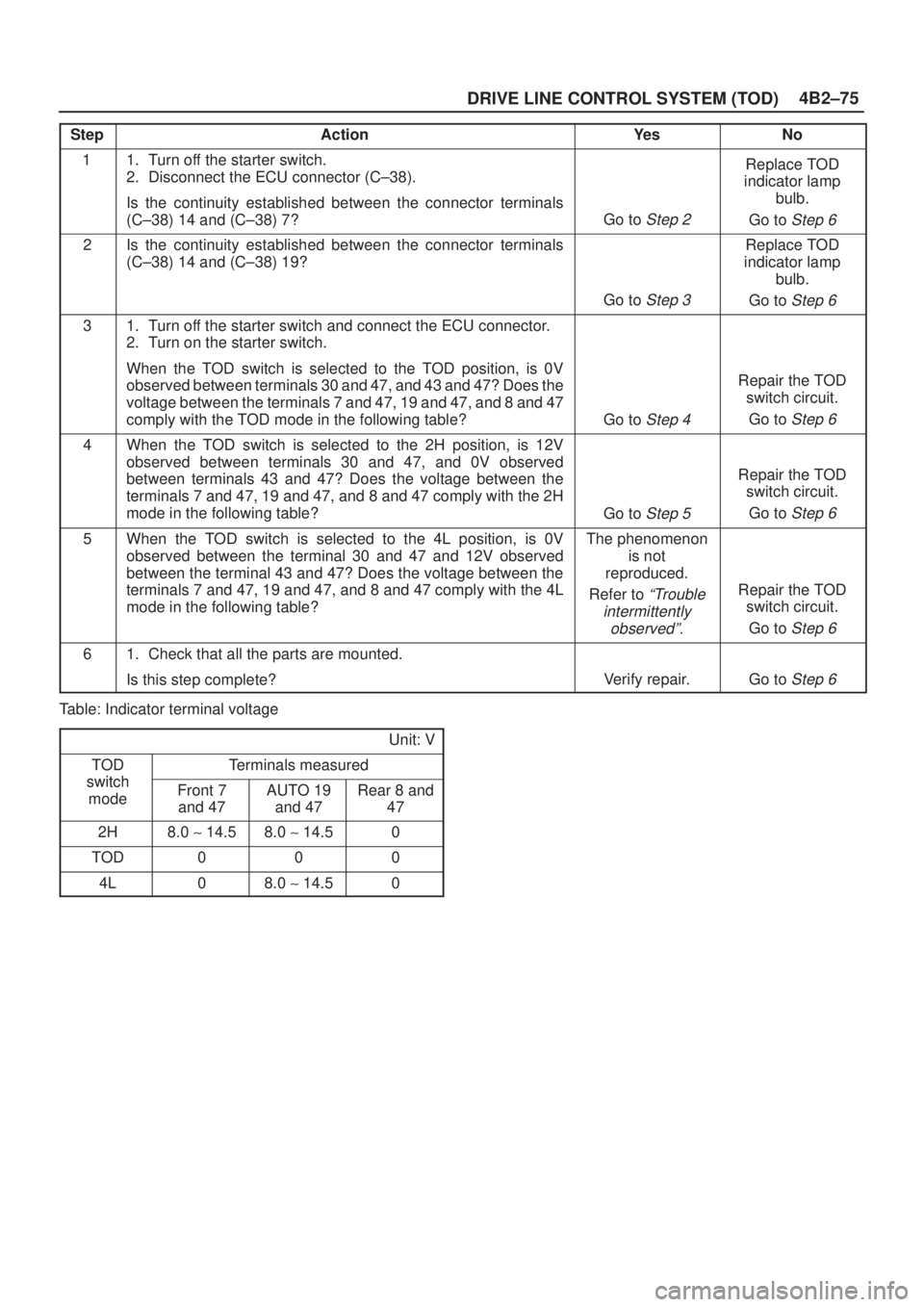
4B2±75
DRIVE LINE CONTROL SYSTEM (TOD)
StepActionYe sNo
11. Turn off the starter switch.
2. Disconnect the ECU connector (C±38).
Is the continuity established between the connector terminals
(C±38) 14 and (C±38) 7?
Go to Step 2
Replace TOD
indicator lamp
bulb.
Go to
Step 6
2Is the continuity established between the connector terminals
(C±38) 14 and (C±38) 19?
Go to Step 3
Replace TOD
indicator lamp
bulb.
Go to
Step 6
31. Turn off the starter switch and connect the ECU connector.
2. Turn on the starter switch.
When the TOD switch is selected to the TOD position, is 0V
observed between terminals 30 and 47, and 43 and 47? Does the
voltage between the terminals 7 and 47, 19 and 47, and 8 and 47
comply with the TOD mode in the following table?
Go to Step 4
Repair the TOD
switch circuit.
Go to
Step 6
4When the TOD switch is selected to the 2H position, is 12V
observed between terminals 30 and 47, and 0V observed
between terminals 43 and 47? Does the voltage between the
terminals 7 and 47, 19 and 47, and 8 and 47 comply with the 2H
mode in the following table?
Go to Step 5
Repair the TOD
switch circuit.
Go to
Step 6
5When the TOD switch is selected to the 4L position, is 0V
observed between the terminal 30 and 47 and 12V observed
between the terminal 43 and 47? Does the voltage between the
terminals 7 and 47, 19 and 47, and 8 and 47 comply with the 4L
mode in the following table?The phenomenon
is not
reproduced.
Refer to
ªTrouble
intermittently
observedº.Repair the TOD
switch circuit.
Go to
Step 6
61. Check that all the parts are mounted.
Is this step complete?
Verify repair.Go to Step 6
Table: Indicator terminal voltage
Unit: V
TOD
switch
Terminals measured
switch
modeFront 7
and 47AUTO 19
and 47Rear 8 and
47
2H8.0 ~ 14.58.0 ~ 14.50
TOD000
4L08.0 ~ 14.50
Page 455 of 2100
DRIVE LINE CONTROL SYSTEM (TOD) 4B2±76
Chart B±3The TOD switch B circuit is shorted to GND or broken.
Function of circuitÐ
Fail conditionEven after the transfer mode is selected from TOD to 4L, the indicator lamp state does
not change.
Indicator lamp state
TOD switch position4L
Page 456 of 2100
4B2±77
DRIVE LINE CONTROL SYSTEM (TOD)
D04R200022
Page 457 of 2100

DRIVE LINE CONTROL SYSTEM (TOD) 4B2±78
StepActionYe sNo
11. Turn on the starter switch.
When the TOD switch is selected to the TOD position, is 0V
observed between terminals 30 and 47, and 43 and 47? Does the
voltage between the terminals 7 and 47, 19 and 47, and 8 and 47
comply with the TOD mode in the following table?
Go to Step 2
Repair the TOD
switch circuit.
Go to
Step 4
2When the TOD switch is selected to the 2H position, is 12V
observed between terminals 30 and 47, and 0V observed
between terminals 43 and 47? Does the voltage between the
terminals 7 and 47, 19 and 47, and 8 and 47 comply with the 2H
mode in the following table?
Go to Step 3
Repair the TOD
switch circuit.
Go to
Step 4
3When the TOD switch is selected to the 4L position, is 0V
observed between the terminal 30 and 47 and 12V observed
between the terminal 43 and 47? Does the voltage between the
terminals 7 and 47, 19 and 47, and 8 and 47 comply with the 4L
mode in the following table?The phenomenon
is not
reproduced.
Refer to
ªTrouble
intermittentry
observedº.Repair the TOD
switch circuit.
Go to
Step 4
41. Check that all the parts are mounted.
Is this step complete?
Verify repair.Go to Step 4
Table: Indicator terminal voltage
Unit: V
TOD
switch
Terminals measured
switch
modeFront 7
and 47AUTO 19
and 47Rear 8 and
47
2H8.0 ~ 14.58.0 ~ 14.50
TOD000
4L08.0 ~ 14.50
Page 458 of 2100
4B2±79
DRIVE LINE CONTROL SYSTEM (TOD)
Chart B±4The TOD switch B circuit is shorted to battery.
Function of circuitÐ
Fail conditionEven after the transfer mode is selected from 4L to TOD, the indicator lamp state does
not change.
Indicator lamp state
TOD switch positionTOD
Page 459 of 2100
DRIVE LINE CONTROL SYSTEM (TOD) 4B2±80
D04R200022
Page 460 of 2100

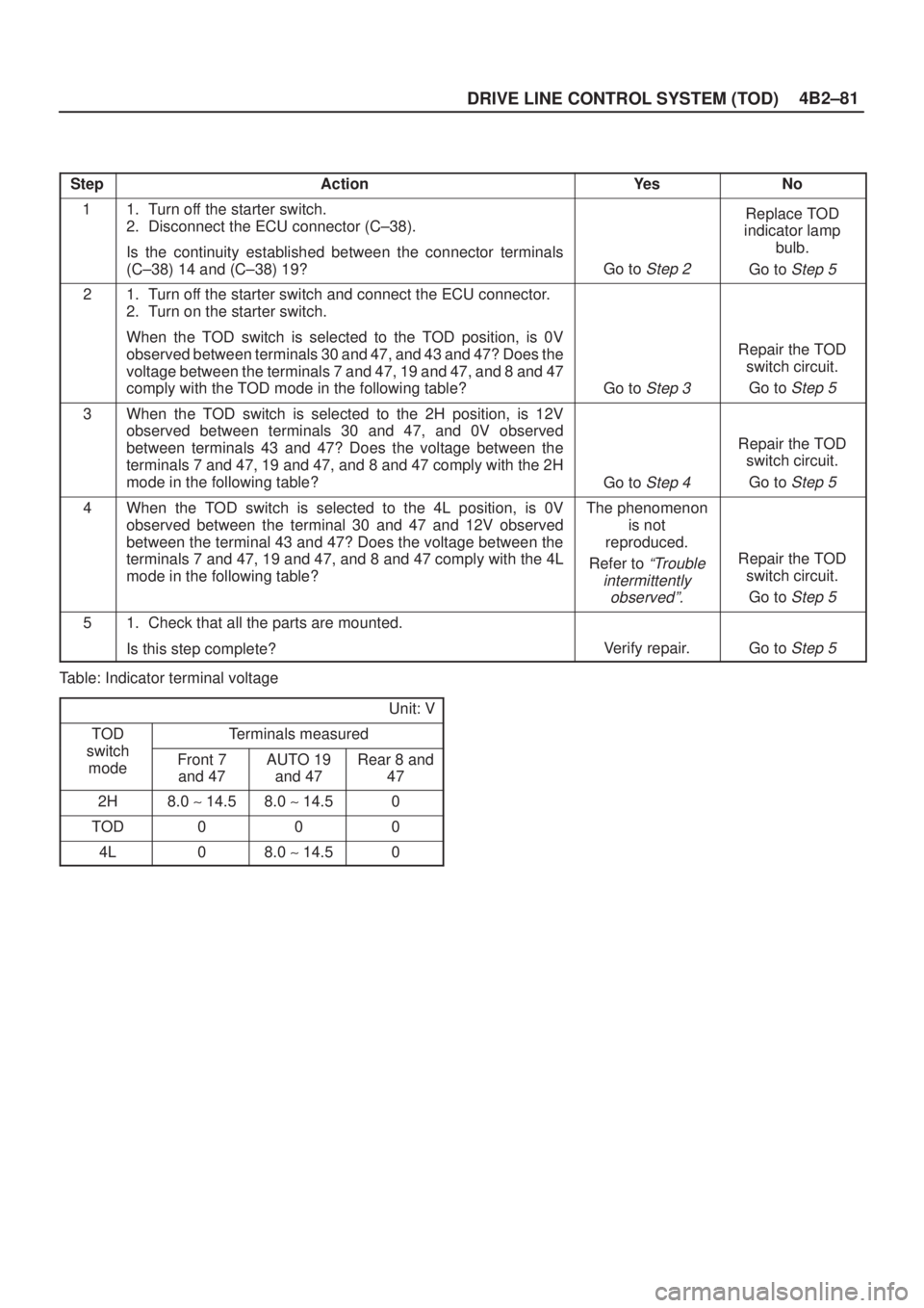
4B2±81
DRIVE LINE CONTROL SYSTEM (TOD)
StepActionYe sNo
11. Turn off the starter switch.
2. Disconnect the ECU connector (C±38).
Is the continuity established between the connector terminals
(C±38) 14 and (C±38) 19?
Go to Step 2
Replace TOD
indicator lamp
bulb.
Go to
Step 5
21. Turn off the starter switch and connect the ECU connector.
2. Turn on the starter switch.
When the TOD switch is selected to the TOD position, is 0V
observed between terminals 30 and 47, and 43 and 47? Does the
voltage between the terminals 7 and 47, 19 and 47, and 8 and 47
comply with the TOD mode in the following table?
Go to Step 3
Repair the TOD
switch circuit.
Go to
Step 5
3When the TOD switch is selected to the 2H position, is 12V
observed between terminals 30 and 47, and 0V observed
between terminals 43 and 47? Does the voltage between the
terminals 7 and 47, 19 and 47, and 8 and 47 comply with the 2H
mode in the following table?
Go to Step 4
Repair the TOD
switch circuit.
Go to
Step 5
4When the TOD switch is selected to the 4L position, is 0V
observed between the terminal 30 and 47 and 12V observed
between the terminal 43 and 47? Does the voltage between the
terminals 7 and 47, 19 and 47, and 8 and 47 comply with the 4L
mode in the following table?The phenomenon
is not
reproduced.
Refer to
ªTrouble
intermittently
observedº.Repair the TOD
switch circuit.
Go to
Step 5
51. Check that all the parts are mounted.
Is this step complete?
Verify repair.Go to Step 5
Table: Indicator terminal voltage
Unit: V
TOD
switch
Terminals measured
switch
modeFront 7
and 47AUTO 19
and 47Rear 8 and
47
2H8.0 ~ 14.58.0 ~ 14.50
TOD000
4L08.0 ~ 14.50
Trending: tire pressure, spark plugs, check engine, transmission oil, overheating, fuel type, fuel filter


