lock ISUZU KB P190 2007 Workshop Owners Manual
[x] Cancel search | Manufacturer: ISUZU, Model Year: 2007, Model line: KB P190, Model: ISUZU KB P190 2007Pages: 6020, PDF Size: 70.23 MB
Page 618 of 6020
BRAKE CONTROL SYSTEM 5A-25
“ABS” Warning Lamp
W hen ABS and problems occur that actuate the “ABS”
warning lamp, the code corresponding to the problem is
stored in the EHCU. Only ordinary braking is available
when the ABS is deactivated. Even when the “ABS”
warning lamp is actuated, if the starter switch is set ON
after setting it OFF once, the EHCU checks up on the
entire system. If there is no abnormality, the EHCU
judges ABS to work correctly and the warning lamp is lit
normally, even though the problem code is stored.
NOTE: Illumination of the “ABS” warning lamp indicates
that anti-lock braking is no longer available. Power
assisted braking without anti-lock control is still
available.
Normal Operation
“ABS ” Warning Lamp
W hen the ignition is first moved from “OFF” to “RUN”,
the amber “ABS” warning lamp will turn “ON”. The
“ABS” warning lamp will turn “ON” during engine
starting and will usually stay “ON” for approximately
three seconds after the ignition switch is returned to the
“ON” position. The warning lamp should remain “OFF”
at all other times.
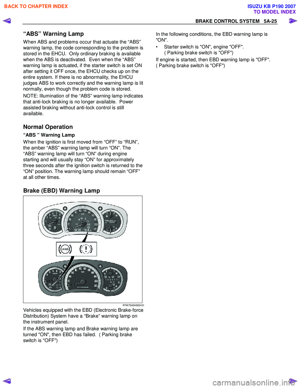
Brake (EBD) Warning Lamp
RTW 75ASH000101
Vehicles equipped with the EBD (Electronic Brake-force
Distribution) System have a “Brake” warning lamp on
the instrument panel.
If the ABS warning lamp and Brake warning lamp are
turned "ON", then EBD has failed. ( Parking brake
switch is "OFF")
In the following conditions, the EBD warning lamp is
"ON".
• Starter switch is "ON", engine "OFF". ( Parking brake switch is "OFF")
If engine is started, then EBD warning lamp is "OFF".
( Parking brake switch is "OFF")
BACK TO CHAPTER INDEX
TO MODEL INDEX
ISUZU KB P190 2007
Page 623 of 6020
5A-30 BRAKE CONTROL SYSTEM
4. Release the brake pedal.
5. Make sure that the front left hold solenoid valve "ON" aimed at by Tech 2 and the wheel locked
position are the same.
If different, check brake pipe, valve line harness wiring
and hydraulic unit. Repair is needed if abnormality is
found.
Front Left Release Valve Test
Purpose: The purpose of this test is to detect brake pipe
and valve line harness wire for incorrect connections and
valve problem.
This test will help you confirm the result of your repai
r
service including the removal/ reinstallation of brake
pipe, valve line harness and valve.
Test conditions: The ignition key is in the "ON" position
with the four wheels lifted up. The brake pedal is stepped
on, released and stepped on again with the parking
brake released.
Test Procedure: 1. Connect Tech 2 with the vehicle, and select "Actuator Test" menus.
2. Select a "Front Left Release Valve Test" menu from the "Actuator Test" menus.
3. Step on the brake pedal.
4. Make sure that the front left release solenoid valve "ON" aimed at by Tech 2 and the wheel released
position are the same.
If different, check brake pipe, valve line harness wiring
and hydraulic unit. Repair is needed if abnormality is
found.
Front Right Hold Valve Test
Purpose: The purpose of this test is to detect brake pipe
and valve line harness wire for incorrect connections and
valve problem.
This test will help you confirm the result of your repai
r
service including the removal/ reinstallation of brake
pipe, valve line harness and valve.
Test conditions: The ignition key is in the "ON" position
with the four wheels lifted up. The brake pedal is stepped
on, released and stepped on again with the parking
brake released.
Test Procedure: 1. Connect Tech 2 with the vehicle, and select "Actuator Test" menus.
2. Select a "Front Right Hold Valve Test" menu from the "Actuator Test" menus.
3. Step on the brake pedal.
4. Release the brake pedal.
5. Make sure that the front right hold solenoid valve "ON" aimed at by Tech 2 and the wheel locked
position are the same.
If different, check brake pipe, valve line harness wiring
and hydraulic unit. Repair is needed if abnormality is
found.
Front Right Release Valve Test
Purpose: The purpose of this test is to detect brake pipe
and valve line harness wire for incorrect connections
and valve problem.
This test will help you confirm the result of your repai
r
service including the removal/ reinstallation of brake
pipe, valve line harness and valve.
Test conditions: The ignition key is in the "ON" position
with the four wheels lifted up. The brake pedal is
stepped on, released and stepped on again with the
parking brake released.
Test Procedure: 1. Connect Tech 2 with the vehicle, and selec
t
"Actuator Test" menus.
2. Select a "Front Right Release Valve Test" menu from the "Actuator Test" menus.
3. Step on the brake pedal.
4. Make sure that the front right release solenoid valve "ON" aimed at by Tech 2 and the wheel released
position are the same.
If different, check brake pipe, valve line harness wiring
and hydraulic unit. Repair is needed if abnormality is
found.
Rear Hold Valve Test
Purpose: The purpose of this test is to detect brake pipe
and valve line harness wire for incorrect connections
and valve problem.
This test will help you confirm the result of your repai
r
service including the removal/ reinstallation of brake
pipe, valve line harness and valve.
Test conditions: The ignition key is in the "ON" position
with the four wheels lifted up. The brake pedal is
stepped on, released and stepped on again with the
parking brake released.
Test Procedure: 1. Connect Tech 2 with the vehicle, and selec
t
"Actuator Test" menus.
BACK TO CHAPTER INDEX
TO MODEL INDEX
ISUZU KB P190 2007
Page 624 of 6020
BRAKE CONTROL SYSTEM 5A-31
2. Select a "Rear Hold Valve Test" menu from the
"Actuator Test" menus.
3. Step on the brake pedal.
4. Release the brake pedal.
5. Make sure that the rear hold solenoid valve "ON" aimed at by Tech 2 and the wheel locked position
are the same.
If different, check brake pipe, valve line harness wiring
and hydraulic unit. Repair is needed if abnormality is
found.
Rear Release Valve Test
Purpose: The purpose of this test is to detect brake pipe
and valve line harness wire for incorrect connections and
valve problem.
This test will help you confirm the result of your repai
r
service including the removal/ reinstallation of brake
pipe, valve line harness and valve.
Test conditions: The ignition key is in the "ON" position
with the four wheels lifted up. The brake pedal is stepped
on, released and stepped on again with the parking
brake released.
Test Procedure: 1. Connect Tech 2 with the vehicle, and select "Actuator Test" menus.
2. Select a "Rear Release Valve Test" menu from the "Actuator Test" menus.
3. Step on the brake pedal.
4. Make sure that the rear release solenoid valve "ON" aimed at by Tech 2 and the wheel released position
are the same.
If different, check brake pipe, valve line harness wiring
and hydraulic unit. Repair is needed if abnormality is
found.
BACK TO CHAPTER INDEX
TO MODEL INDEX
ISUZU KB P190 2007
Page 635 of 6020
5A-42 BRAKE CONTROL SYSTEM
Symptom Diagnosis
The symptoms that cannot be indicated by warning
lamp can be divided into the following six categories:
1. ABS works frequently but vehicle does not decelerate.
2. Uneven braking occurs while ABS works.
3. The wheels are locked.
4. Brake pedal feel is abnormal.
5. Braking sound (from EHCU) is heard while not braking.
6. No ABS warning lamp
These are all attributable to problems which cannot be
detected by EHCU self-diagnosis. Use the customer
complaint and a test to determine which symptom is
present.
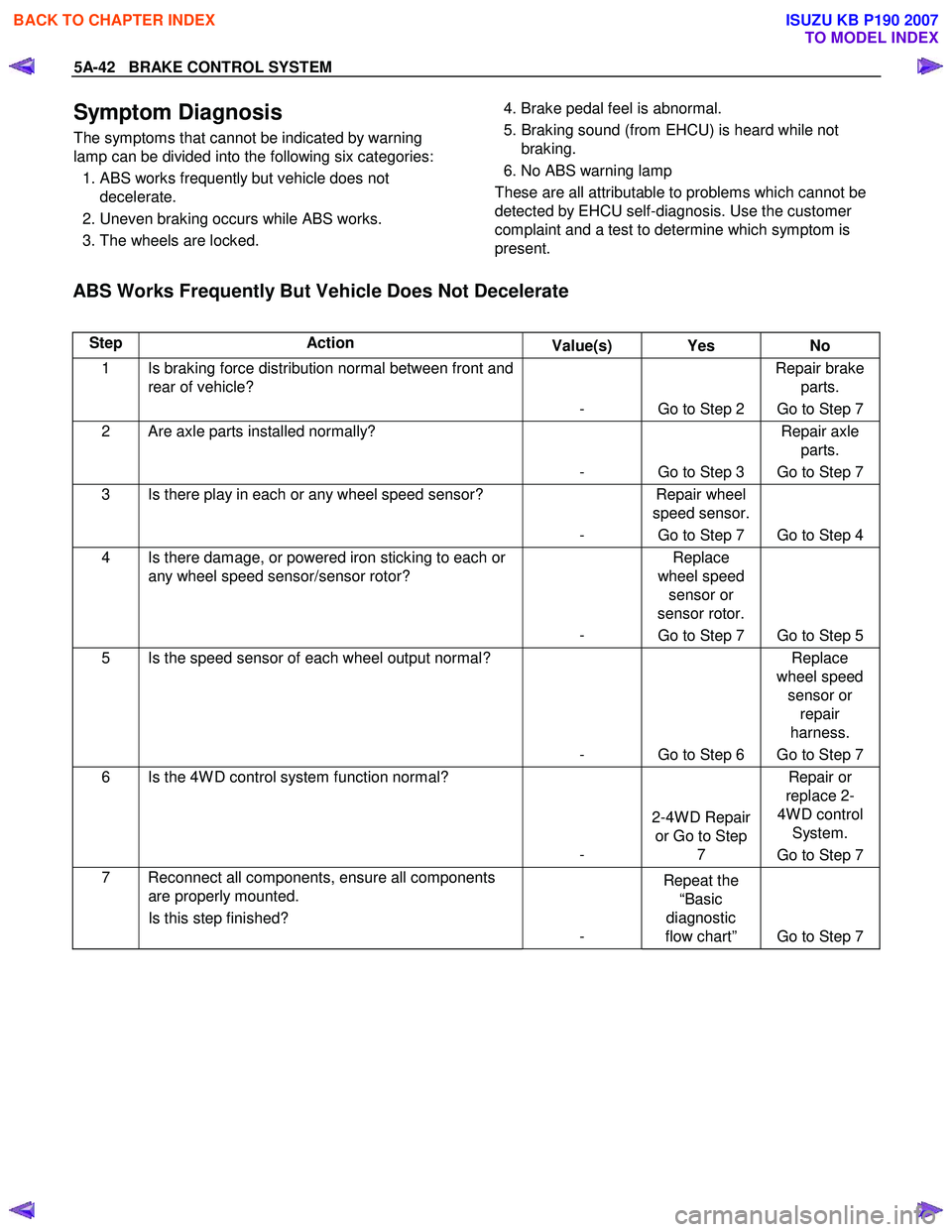
ABS Works Frequently But Vehicle Does Not Decelerate
Step Action Value(s) Yes No
1 Is braking force distribution normal between front and
rear of vehicle?
- Go to Step 2 Repair brake
parts.
Go to Step 7
2 Are axle parts installed normally?
- Go to Step 3 Repair axle
parts.
Go to Step 7
3 Is there play in each or any wheel speed sensor?
- Repair wheel
speed sensor.
Go to Step 7 Go to Step 4
4 Is there damage, or powered iron sticking to each or any wheel speed sensor/sensor rotor?
- Replace
wheel speed sensor or
sensor rotor.
Go to Step 7 Go to Step 5
5 Is the speed sensor of each wheel output normal?
- Go to Step 6 Replace
wheel speed sensor or repair
harness.
Go to Step 7
6 Is the 4W D control system function normal?
- 2-4W D Repair
or Go to Step 7 Repair or
replace 2-
4W D control System.
Go to Step 7
7 Reconnect all components, ensure all components are properly mounted.
Is this step finished? - Repeat the
“Basic
diagnostic
flow chart” Go to Step 7
BACK TO CHAPTER INDEX
TO MODEL INDEX
ISUZU KB P190 2007
Page 636 of 6020
BRAKE CONTROL SYSTEM 5A-43
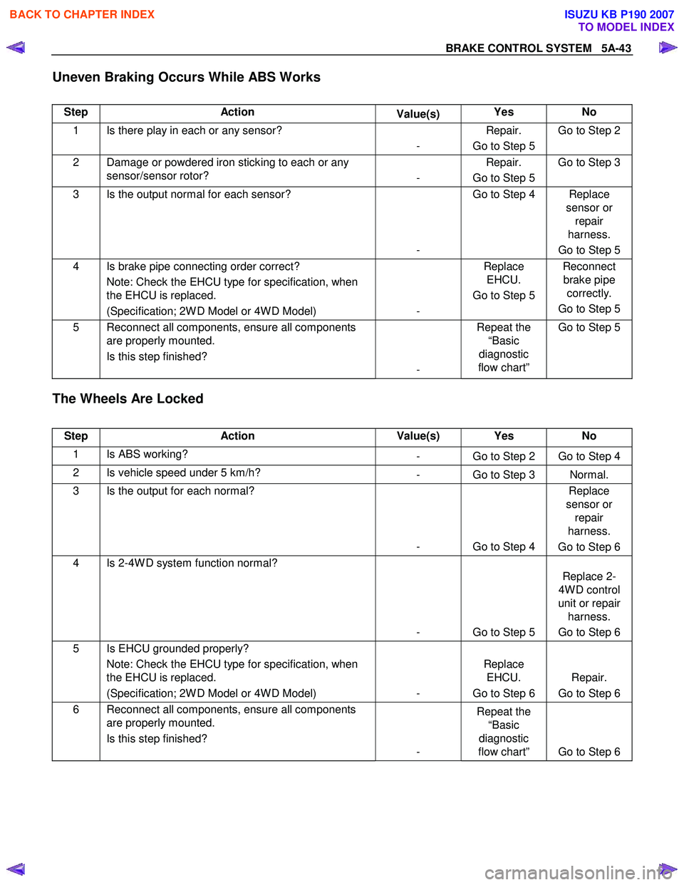
Uneven Braking Occurs While ABS Works
Step Action Value(s) Yes No
1 Is there play in each or any sensor?
- Repair.
Go to Step 5 Go to Step 2
2 Damage or powdered iron sticking to each or any
sensor/sensor rotor? - Repair.
Go to Step 5 Go to Step 3
3 Is the output normal for each sensor?
- Go to Step 4 Replace
sensor or repair
harness.
Go to Step 5
4 Is brake pipe connecting order correct? Note: Check the EHCU type for specification, when
the EHCU is replaced.
(Specification; 2W D Model or 4W D Model) - Replace
EHCU.
Go to Step 5 Reconnect
brake pipe correctly.
Go to Step 5
5 Reconnect all components, ensure all components are properly mounted.
Is this step finished? - Repeat the
“Basic
diagnostic
flow chart” Go to Step 5
The Wheels Are Locked
Step Action Value(s) Yes No
1 Is ABS working?
- Go to Step 2 Go to Step 4
2 Is vehicle speed under 5 km/h? - Go to Step 3 Normal.
3 Is the output for each normal?
- Go to Step 4 Replace
sensor or repair
harness.
Go to Step 6
4 Is 2-4W D system function normal?
- Go to Step 5 Replace 2-
4W D control
unit or repair harness.
Go to Step 6
5 Is EHCU grounded properly? Note: Check the EHCU type for specification, when
the EHCU is replaced.
(Specification; 2W D Model or 4W D Model) - Replace
EHCU.
Go to Step 6 Repair.
Go to Step 6
6 Reconnect all components, ensure all components are properly mounted.
Is this step finished? - Repeat the
“Basic
diagnostic
flow chart” Go to Step 6
BACK TO CHAPTER INDEX
TO MODEL INDEX
ISUZU KB P190 2007
Page 680 of 6020
ANTI-LOCK BRAKE SYSTEM 5B-1
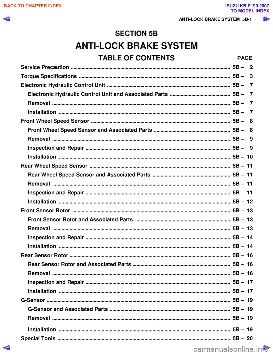
SECTION 5B
ANTI-LOCK BRAKE SYSTEM
TABLE OF CONTENTS PAGE
Ser vice Precau tion ....................................................................................................................... 5B – 2
Torque Specifications ................................................................................................................. 5B – 3
Electronic Hydraulic Control Unit ............................................................................................ 5B – 7
Electronic Hydraulic Control Unit and Associated Parts ............................................. 5B – 7
Removal ..................................................................................................................................... 5B – 7
Installation ............................................................................................................................... . 5B – 7
Front Wheel Speed Sensor ........................................................................................................ 5B – 8
Front Wheel Speed Sensor and Associated Parts ......................................................... 5B – 8
Removal ..................................................................................................................................... 5B – 9
Inspection and Repair ............................................................................................................ 5B – 9
Installation ............................................................................................................................... . 5B – 10
Rear Wheel Speed Sensor ......................................................................................................... 5B – 11
Rear Wheel Speed Sensor and Associated Parts .......................................................... 5B – 11
Removal ..................................................................................................................................... 5B – 11
Inspection and Repair ............................................................................................................ 5B – 11
Installation ............................................................................................................................... . 5B – 12
Front Sensor Rotor ...................................................................................................................... 5B – 13
Front Sensor Rotor and Associated Parts ....................................................................... 5B – 13
Removal ..................................................................................................................................... 5B – 13
Inspection and Repair ............................................................................................................ 5B – 14
Installation ............................................................................................................................... . 5B – 14
Rear Sensor Rotor ........................................................................................................................ 5B – 16
Rear Sensor Rotor and Associated Parts ......................................................................... 5B – 16
Removal ..................................................................................................................................... 5B – 16
Inspection and Repair ............................................................................................................ 5B – 17
Installation ............................................................................................................................... . 5B – 17
G-Sensor .............................................................................................................................. ........... 5B – 19
G-Sensor and Associated Parts .......................................................................................... 5B – 19
Removal ..................................................................................................................................... 5B – 19
Installation ............................................................................................................................... . 5B – 19
Special Tools ................................................................................................................................. 5B – 20
BACK TO CHAPTER INDEX
TO MODEL INDEX
ISUZU KB P190 2007
Page 681 of 6020

5B-2 ANTI-LOCK BRAKE SYSTEM
Service Precaution
WARNING: THIS VEHICLE HAS A SUPPLEMENTAL
RESTRAINT SYSTEM (SRS). REFER TO THE SRS
COMPONENT AND WIRING LOCATION VIEW IN
ORDER TO DETERMINE WHETHER YOU ARE
PERFORMING SERVICE ON OR NEAR THE SRS
COMPONENTS OR THE SRS WIRING. WHEN YOU
ARE PERFORMING SERVICE ON OR NEAR THE
SRS COMPONENTS OR THE SRS WIRING, REFER
TO THE SRS SERVICE INFORMATION. FAILURE TO
FOLLOW WARNINGS COULD RESULT IN POSSIBLE
AIR BAG DEPLOYMENT, PERSONAL INJURY, OR
OTHERWISE UNNECESSARY SRS SYSTEM
REPAIRS.
CAUTION: Always use the correct fastener in the
proper location. When you replace a fastener, use
ONLY the exact part number for that application.
ISUZU/GM will call out those fasteners that require a
replacement after removal. ISUZU/GM will also call
out the fasteners that require thread lockers o
r
thread sealant. UNLESS OTHERWISE SPECIFIED,
do not use supplemental coatings (paints, greases,
or other corrosion inhibitors) on threaded fasteners
or fastener joint interfaces. Generally, such coatings
adversely affect the fastener torque and the joint
clamping force, and may damage the fastener.
When you install fasteners, use the correct
tightening sequence and specifications. Following
these instructions can help you avoid damage to
parts and systems.
BACK TO CHAPTER INDEX
TO MODEL INDEX
ISUZU KB P190 2007
Page 682 of 6020

ANTI-LOCK BRAKE SYSTEM 5B-3
Torque Specifications
Electronic Hydraulic Control Unit N⋅m (kgf ⋅m/lb ⋅ft)
RTW 75BMF000401
BACK TO CHAPTER INDEX
TO MODEL INDEX
ISUZU KB P190 2007
Page 683 of 6020

5B-4 ANTI-LOCK BRAKE SYSTEM
4×
××
×
2 (Except High Ride Suspension) Front Wheel Speed Sensor N⋅m (kgf ⋅m/lb ⋅ft)
RTW 55ALF000301
BACK TO CHAPTER INDEX
TO MODEL INDEX
ISUZU KB P190 2007
Page 684 of 6020

ANTI-LOCK BRAKE SYSTEM 5B-5
4×
××
×
2 High Ride Suspension, 4 ×
××
×
4 Front Wheel Speed Sensor N⋅m (kgf ⋅m/lb ⋅ft)
RTW 55ALF000101
BACK TO CHAPTER INDEX
TO MODEL INDEX
ISUZU KB P190 2007