lock ISUZU KB P190 2007 Workshop Repair Manual
[x] Cancel search | Manufacturer: ISUZU, Model Year: 2007, Model line: KB P190, Model: ISUZU KB P190 2007Pages: 6020, PDF Size: 70.23 MB
Page 732 of 6020
BRAKES 5C-33
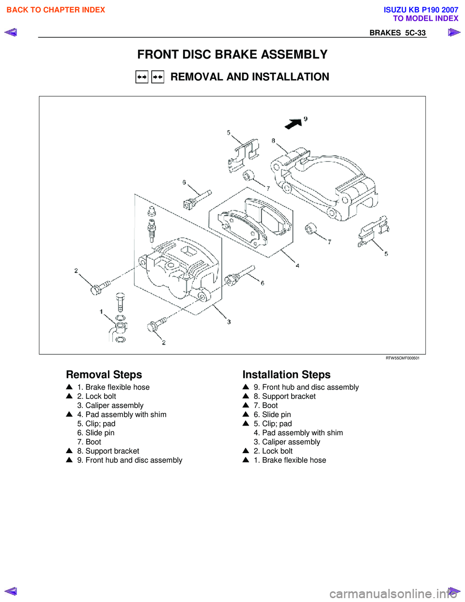
FRONT DISC BRAKE ASSEMBLY
REMOVAL AND INSTALLATION
RTW 55CMF000501
Removal Steps
1. Brake flexible hose
2. Lock bolt
3. Caliper assembly
4. Pad assembly with shim
5. Clip; pad
6. Slide pin
7. Boot
8. Support bracket
9. Front hub and disc assembly
Installation Steps
9. Front hub and disc assembly
8. Support bracket
7. Boot
6. Slide pin
5. Clip; pad
4. Pad assembly with shim
3. Caliper assembly
2. Lock bolt
1. Brake flexible hose
BACK TO CHAPTER INDEX
TO MODEL INDEX
ISUZU KB P190 2007
Page 733 of 6020
5C-34 BRAKES
RUW 55CSH000101
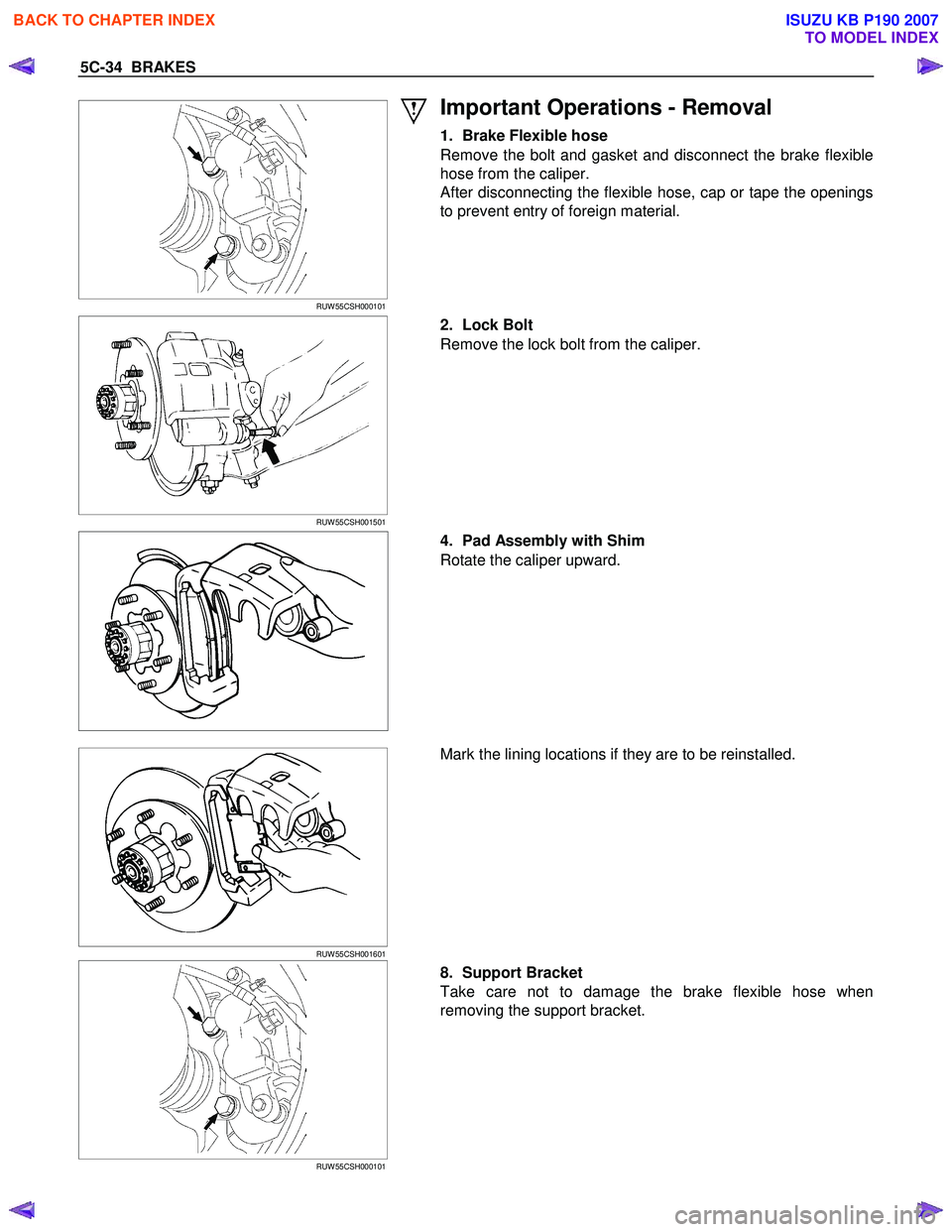
Important Operations - Removal
1. Brake Flexible hose
Remove the bolt and gasket and disconnect the brake flexible
hose from the caliper.
After disconnecting the flexible hose, cap or tape the openings
to prevent entry of foreign material.
RUW 55CSH001501
2. Lock Bolt
Remove the lock bolt from the caliper.
4. Pad Assembly with Shim
Rotate the caliper upward.
RUW 55CSH001601
Mark the lining locations if they are to be reinstalled.
RUW 55CSH000101
8. Support Bracket
Take care not to damage the brake flexible hose when
removing the support bracket.
BACK TO CHAPTER INDEX
TO MODEL INDEX
ISUZU KB P190 2007
Page 734 of 6020
BRAKES 5C-35
9. Front Hub and Disc Assembly
For the removal procedure, refer to Section 4C “FRONT
W HEEL DRIVE”.
Important Operations - Installation
9. Front Hub and Disc Assembly
For the installation procedure, refer to the front hub and disc
reassembly procedure in Section 4C “FRONT W HEEL
DRIVE”.
RUW 55CSH000101
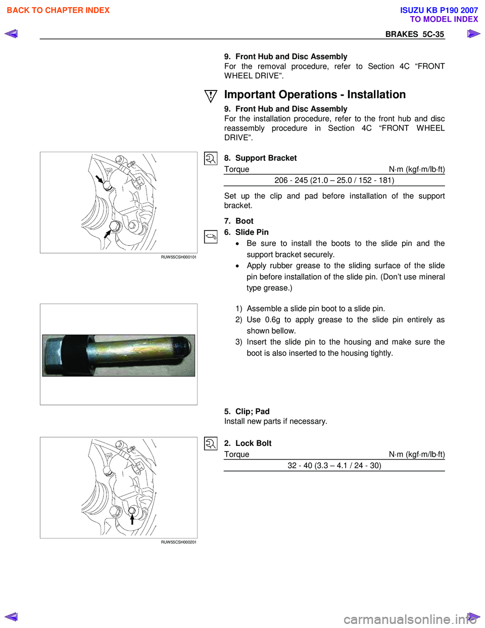
8. Support Bracket
Torque N ⋅m (kgf ⋅m/lb ⋅ft)
206 - 245 (21.0 – 25.0 / 152 - 181)
Set up the clip and pad before installation of the support
bracket.
7. Boot
6. Slide Pin • Be sure to install the boots to the slide pin and the
support bracket securely.
•
Apply rubber grease to the sliding surface of the slide
pin before installation of the slide pin. (Don’t use mineral
type grease.)
1) Assemble a slide pin boot to a slide pin.
2) Use 0.6g to apply grease to the slide pin entirely as shown bellow.
3) Insert the slide pin to the housing and make sure the boot is also inserted to the housing tightly.
5. Clip; Pad
Install new parts if necessary.
RUW 55CSH000201
2. Lock Bolt
Torque N ⋅m (kgf ⋅m/lb ⋅ft)
32 - 40 (3.3 – 4.1 / 24 - 30)
BACK TO CHAPTER INDEX
TO MODEL INDEX
ISUZU KB P190 2007
Page 736 of 6020
BRAKES 5C-37
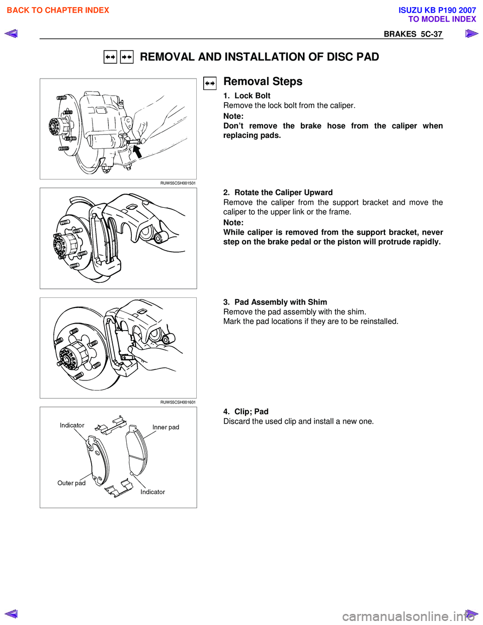
REMOVAL AND INSTALLATION OF DISC PAD
RUW 55CSH001501
Removal Steps
1. Lock Bolt
Remove the lock bolt from the caliper.
Note:
Don’t remove the brake hose from the caliper when
replacing pads.
2. Rotate the Caliper Upward
Remove the caliper from the support bracket and move the
caliper to the upper link or the frame.
Note:
While caliper is removed from the support bracket, neve
r
step on the brake pedal or the piston will protrude rapidly.
RUW 55CSH001601
3. Pad Assembly with Shim
Remove the pad assembly with the shim.
Mark the pad locations if they are to be reinstalled.
4. Clip; Pad
Discard the used clip and install a new one.
BACK TO CHAPTER INDEX
TO MODEL INDEX
ISUZU KB P190 2007
Page 737 of 6020
5C-38 BRAKES
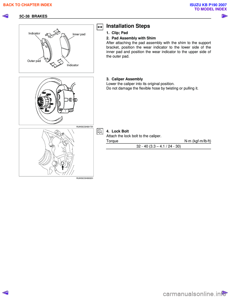
Installation Steps
1. Clip; Pad
2. Pad Assembly with Shim
After attaching the pad assembly with the shim to the support
bracket, position the wear indicator to the lower side of the
inner pad and position the wear indicator to the upper side o
f
the outer pad.
RUW 55CSH001701
3. Caliper Assembly
Lower the caliper into its original position.
Do not damage the flexible hose by twisting or pulling it.
RUW 55CSH000201
4. Lock Bolt
Attach the lock bolt to the caliper.
Torque N ⋅m (kgf ⋅m/lb ⋅ft)
32 - 40 (3.3 – 4.1 / 24 - 30)
BACK TO CHAPTER INDEX
TO MODEL INDEX
ISUZU KB P190 2007
Page 738 of 6020
BRAKES 5C-39
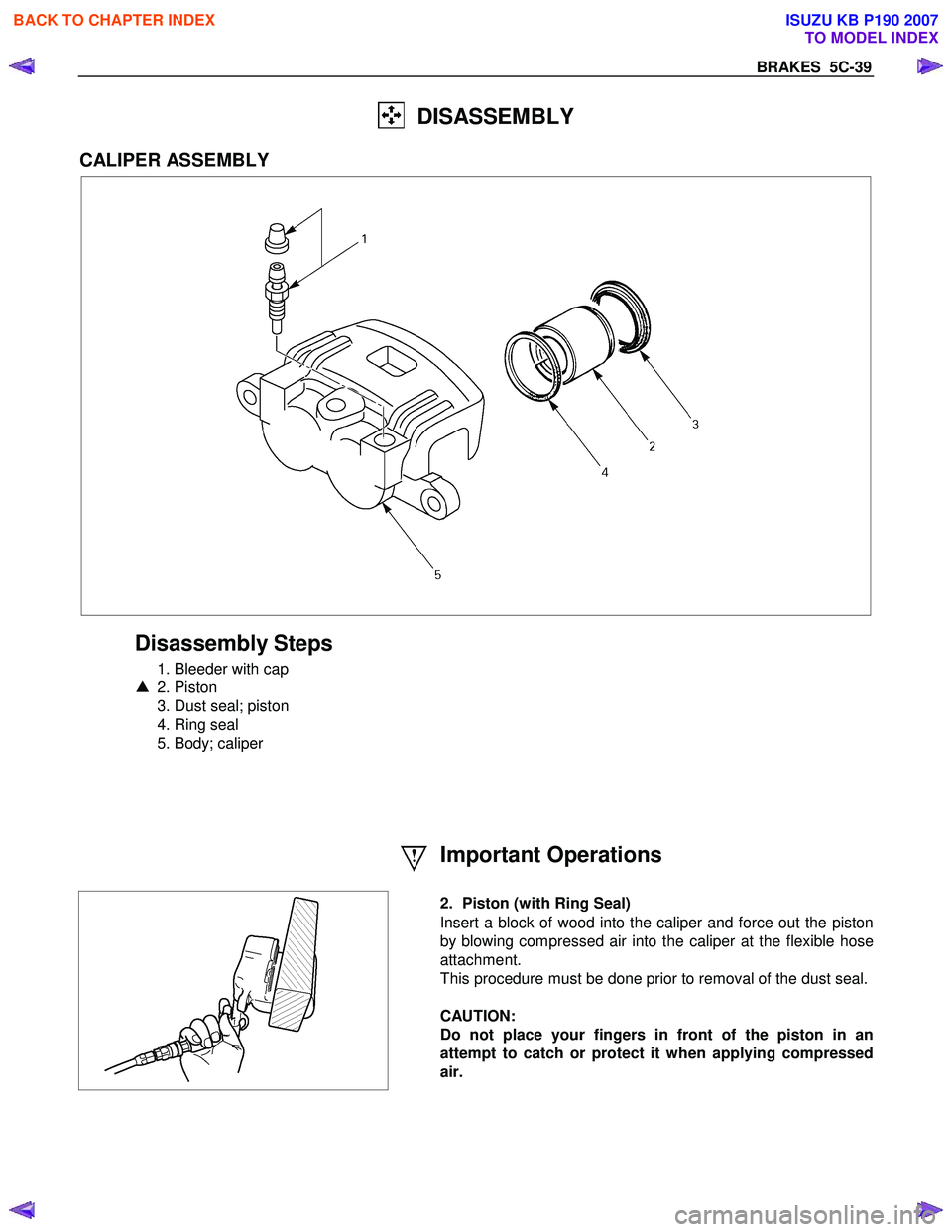
DISASSEMBLY
CALIPER ASSEMBLY
Disassembly Steps
1. Bleeder with cap
▲ 2. Piston
3. Dust seal; piston
4. Ring seal
5. Body; caliper
Important Operations
2. Piston (with Ring Seal)
Insert a block of wood into the caliper and force out the piston
by blowing compressed air into the caliper at the flexible hose
attachment.
This procedure must be done prior to removal of the dust seal.
CAUTION:
Do not place your fingers in front of the piston in an
attempt to catch or protect it when applying compressed
air.
BACK TO CHAPTER INDEX
TO MODEL INDEX
ISUZU KB P190 2007
Page 739 of 6020
5C-40 BRAKES
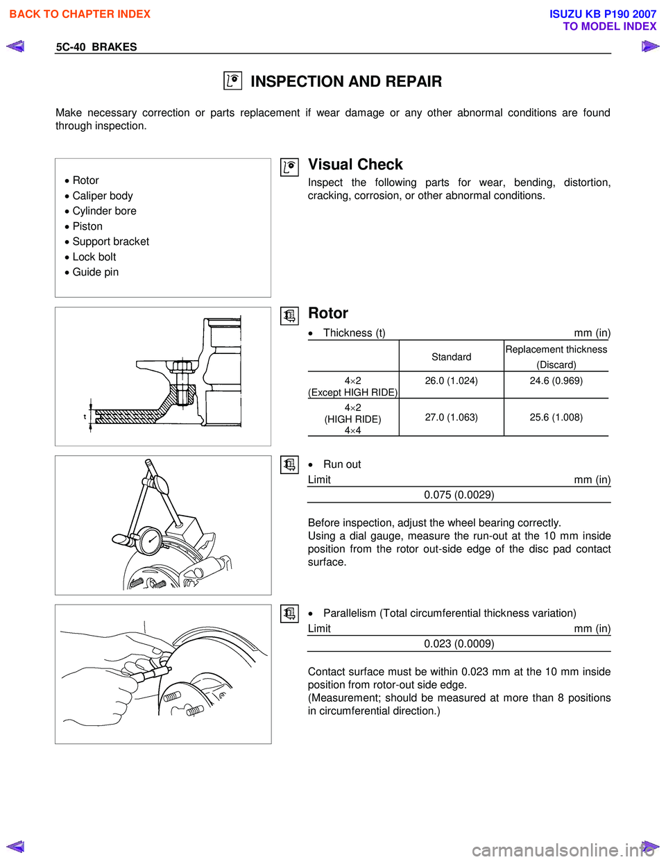
INSPECTION AND REPAIR
Make necessary correction or parts replacement if wear damage or any other abnormal conditions are found
through inspection.
• Rotor
• Caliper body
• Cylinder bore
• Piston
• Support bracket
• Lock bolt
• Guide pin
Visual Check
Inspect the following parts for wear, bending, distortion,
cracking, corrosion, or other abnormal conditions.
Rotor
• Thickness (t) mm (in)
StandardReplacement thickness
(Discard)
4×2
(Except HIGH RIDE) 26.0 (1.024)
24.6 (0.969)
4×2
(HIGH RIDE) 4×4 27.0 (1.063) 25.6 (1.008)
•
Run out
Limit mm (in)
0.075 (0.0029)
Before inspection, adjust the wheel bearing correctly.
Using a dial gauge, measure the run-out at the 10 mm inside
position from the rotor out-side edge of the disc pad contact
surface.
•
Parallelism (Total circumferential thickness variation)
Limit mm (in)
0.023 (0.0009)
Contact surface must be within 0.023 mm at the 10 mm inside
position from rotor-out side edge.
(Measurement; should be measured at more than 8 positions
in circumferential direction.)
BACK TO CHAPTER INDEX
TO MODEL INDEX
ISUZU KB P190 2007
Page 742 of 6020
BRAKES 5C-43
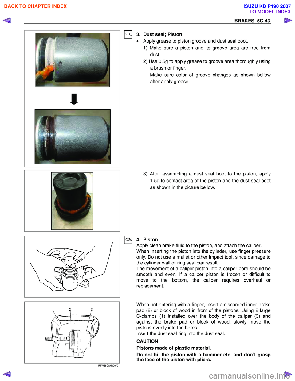
3. Dust seal; Piston
• Apply grease to piston groove and dust seal boot.
1) Make sure a piston and its groove area are free from dust.
2) Use 0.5g to apply grease to groove area thoroughly using a brush or finger.
Make sure color of groove changes as shown bello
w
after apply grease.
3) After assembling a dust seal boot to the piston, apply
1.5g to contact area of the piston and the dust seal boot
as shown in the picture bellow.
4. Piston
Apply clean brake fluid to the piston, and attach the caliper.
W hen inserting the piston into the cylinder, use finger pressure
only. Do not use a mallet or other impact tool, since damage to
the cylinder wall or ring seal can result.
The movement of a caliper piston into a caliper bore should be
smooth and even. If a caliper piston is frozen or difficult to
move to the bottom, the caliper requires overhaul o
r
replacement.
RTW 35CSH000701
W hen not entering with a finger, insert a discarded inner brake
pad (2) or block of wood in front of the pistons. Using 2 large
C-clamps (1) installed over the body of the caliper (3) and
against the brake pad or block of wood, slowly move the
pistons evenly into the bores.
Insert the dust seal ring into the dust seal.
CAUTION:
Pistons made of plastic material.
Do not hit the piston with a hammer etc. and don’t grasp
the face of the piston with pliers.
BACK TO CHAPTER INDEX
TO MODEL INDEX
ISUZU KB P190 2007
Page 760 of 6020

BRAKES 5C-61
RTW 75CSH002701
Important Operation-Removal
1. Brake pipe
W hen hurdling, be careful not to spill brake fluid over the
painted surfaces, as damage to the paint finish will result.
2. Master Cylinder Fixing Nut
3. Bracket
4. Master Cylinder Assembly
NOTE:
W hen removing the master cylinder from the vacuum booster,
be sure to get rid of the internal negative pressure of the
vacuum booster (by, for instance, disconnecting the vacuum
hose) in advance.
If any negative pressure remains in the vacuum booster, the
piston may possibly come out when the master cylinder is
being removed, letting the brake fluid run out.
W hile removing the master cylinder, do not hold the piston as it
can be easily pulled out.
Inspection and Repair
Vacuum Hose (The built in check valve)
360R300002
1) Inspect the check valve, which is installed inside the
vacuum hose.
2) Blow air into the hose from the booster side as shown in the illustration. The air should pass freely through the
hose.
3) Blow air into the hose from the engine side. The check valve should close to block the passage of air.
The vacuum hose and built-in check valve must be
replaced as a set if either is found to be defective.
Important Operation-Installation
10. Vacuum Booster Assembly
Note:
•
Adjustment of push rod of vacuum booster is not carried
out. W hen vacuum booster is damaged it exchanges for a
new article. (Push rod is adjusted)
• Measurement of primary piston position by the side o
f
master cylinder is unnecessary.
9. Spacer
8. Gasket
7. Vacuum Booster Fixing Nut
6. Snap Pin
Install the vacuum booster assembly to the dash panel and
pedal mounting bracket.
BACK TO CHAPTER INDEX
TO MODEL INDEX
ISUZU KB P190 2007
Page 771 of 6020
PARKING BRAKE SYSTEM 5D-1
Service Precaution
Service Precaution
WARNING: THIS VEHICLE HAS A SUPPLEMENTAL
RESTRAINT SYSTEM (SRS). REFER TO THE SRS
COMPONENT AND WIRING LOCATION VIEW IN
ORDER TO DETERMINE WHETHER YOU ARE
PERFORMING SERVICE ON OR NEAR THE SRS
COMPONENTS OR THE SRS WIRING. WHEN YOU
ARE PERFORMING SERVICE ON OR NEAR THE
SRS COMPONENTS OR THE SRS WIRING, REFER
TO THE SRS SERVICE INFORMATION. FAILURE TO
FOLLOW WARNINGS COULD RESULT IN
POSSIBLE AIR BAG DEPLOYMENT, PERSONAL
INJURY, OR OTHERWISE UNNECESSARY SRS
SYSTEM REPAIRS.
CAUTION: Always use the correct fastener in the
proper location. When you replace a fastener, use
ONLY the exact part number for that application.
ISUZU/GM will call out those fasteners that require
a replacement after removal. ISUZU/GM will also
call out the fasteners that require thread lockers o
r
thread sealant. UNLESS OTHERWISE SPECIFIED,
do not use supplemental coatings (paints, greases,
or other corrosion inhibitors) on threaded fasteners
or fastener joint interfaces. Generally, such
coatings adversely affect the fastener torque and
the joint clamping force, and may damage the
fastener. When you install fasteners, use the
correct tightening sequence and specifications.
Following these instructions can help you avoid
damage to parts and systems.
General Description
Pulling up the parking brake lever by hand will set the
parking brake. By means of a ratchet type lock, the
lever can be held in that position until it is released. The
position of the lever is transmitted through cable/leve
r
systems to the rear wheels. These parts are designed
to obtain sufficient braking force even when parking on
slopes. W hen the parking brake is set, or when the
ignition SW is in the “ON” position, the brake warning
light illuminates. The rear wheel parking brake is a
leading-trailing brake (mechanical inside expansion
type) built in the rear drum brake. Parking brake
adjustment is made through the adjusting hole (bored
through back plate). Parking brake lever stroke should
be adjusted to 8 −14 notches with 294N (30 kg / 66 lb)
(bench seat) or 6 −9 notches with 294N (30 kg / 66 lb)
(bucket seat). Refer to “Parking Brake Adjustment” in
this section.
BACK TO CHAPTER INDEX
TO MODEL INDEX
ISUZU KB P190 2007