battery replacement ISUZU KB P190 2007 Workshop Repair Manual
[x] Cancel search | Manufacturer: ISUZU, Model Year: 2007, Model line: KB P190, Model: ISUZU KB P190 2007Pages: 6020, PDF Size: 70.23 MB
Page 4 of 6020
0A-2 GENERAL INFORMATION
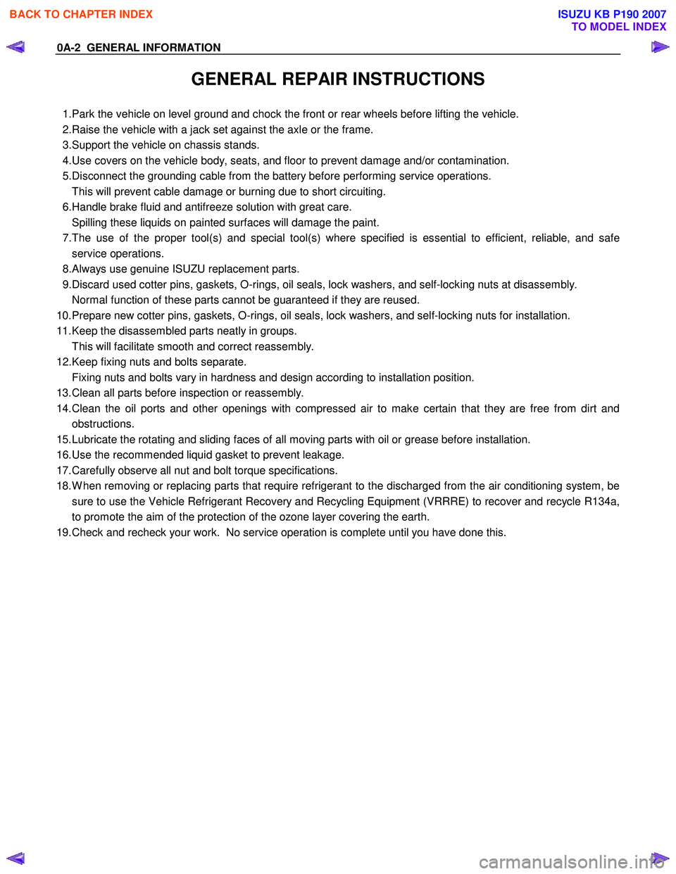
GENERAL REPAIR INSTRUCTIONS
1. Park the vehicle on level ground and chock the front or rear wheels before lifting the vehicle.
2. Raise the vehicle with a jack set against the axle or the frame.
3. Support the vehicle on chassis stands.
4. Use covers on the vehicle body, seats, and floor to prevent damage and/or contamination.
5. Disconnect the grounding cable from the battery before performing service operations.
This will prevent cable damage or burning due to short circuiting.
6. Handle brake fluid and antifreeze solution with great care.
Spilling these liquids on painted surfaces will damage the paint.
7. The use of the proper tool(s) and special tool(s) where specified is essential to efficient, reliable, and safe
service operations.
8. Always use genuine ISUZU replacement parts.
9. Discard used cotter pins, gaskets, O-rings, oil seals, lock washers, and self-locking nuts at disassembly.
Normal function of these parts cannot be guaranteed if they are reused.
10. Prepare new cotter pins, gaskets, O-rings, oil seals, lock washers, and self-locking nuts for installation.
11. Keep the disassembled parts neatly in groups. This will facilitate smooth and correct reassembly.
12. Keep fixing nuts and bolts separate. Fixing nuts and bolts vary in hardness and design according to installation position.
13. Clean all parts before inspection or reassembly.
14. Clean the oil ports and other openings with compressed air to make certain that they are free from dirt and obstructions.
15. Lubricate the rotating and sliding faces of all moving parts with oil or grease before installation.
16. Use the recommended liquid gasket to prevent leakage.
17. Carefully observe all nut and bolt torque specifications.
18. W hen removing or replacing parts that require refrigerant to the discharged from the air conditioning system, be sure to use the Vehicle Refrigerant Recovery and Recycling Equipment (VRRRE) to recover and recycle R134a,
to promote the aim of the protection of the ozone layer covering the earth.
19. Check and recheck your work. No service operation is complete until you have done this.
BACK TO CHAPTER INDEX
TO MODEL INDEX
ISUZU KB P190 2007
Page 64 of 6020
1-30 HEATER AND AIR CONDITIONING
ON-VEHICLE SERVICE
PRECAUTIONS FOR REPLACEMENT OR
REPAIR OF AIR CONDITIONING PARTS
There are certain procedures, practices and precautions that
should be followed when servicing air conditioning systems:
• Keep your work area clean.
• Always wear safety goggle and protective gloves when
working on refrigerant systems.
• Beware of the danger of carbon monoxide fumes caused by
running the engine.
• Beware of discharged refrigerant in enclosed or improperly
ventilated garages.
•
Always disconnect the negative battery cable and discharge
and recover the refrigerant whenever repairing the air
conditioning system.
• W hen discharging and recovering the refrigerant, do not
allow refrigerant to discharge too fast; it will draw
compressor oil out of the system.
• Keep moisture and contaminants out of the system. W hen
disconnecting or removing any lines or parts, use plugs or
caps to close the fittings immediately.
Never remove the caps or plugs until the lines or parts are reconnected or installed.
• W hen disconnecting or reconnecting the lines, use two
wrenches to support the line fitting, to prevent from twisting
or other damage.
• Always install new O-rings whenever a connection is
disassembled.
• Before connecting any hoses or lines, apply new specified
compressor oil to the O-rings.
• W hen removing and replacing any parts which require
discharging the refrigerant circuit, the operations described
in this section must be performed in the following sequence:
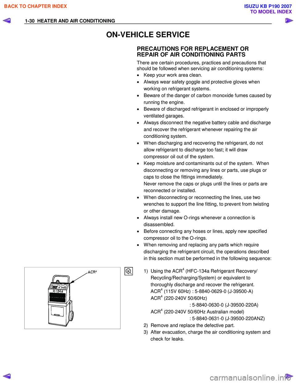
1) Using the ACR
4 (HFC-134a Refrigerant Recovery/
Recycling/Recharging/System) or equivalent to
thoroughly discharge and recover the refrigerant.
ACR
4 (115V 60Hz) : 5-8840-0629-0 (J-39500-A)
ACR4 (220-240V 50/60Hz)
: 5-8840-0630-0 (J-39500-220A)
ACR
4 (220-240V 50/60Hz Australian model)
: 5-8840-0631-0 (J-39500-220ANZ)
2) Remove and replace the defective part.
3)
After evacuation, charge the air conditioning system and
check for leaks.
BACK TO CHAPTER INDEX
TO MODEL INDEX
ISUZU KB P190 2007
Page 1067 of 6020
Engine Control System (4JH1) 6E-33
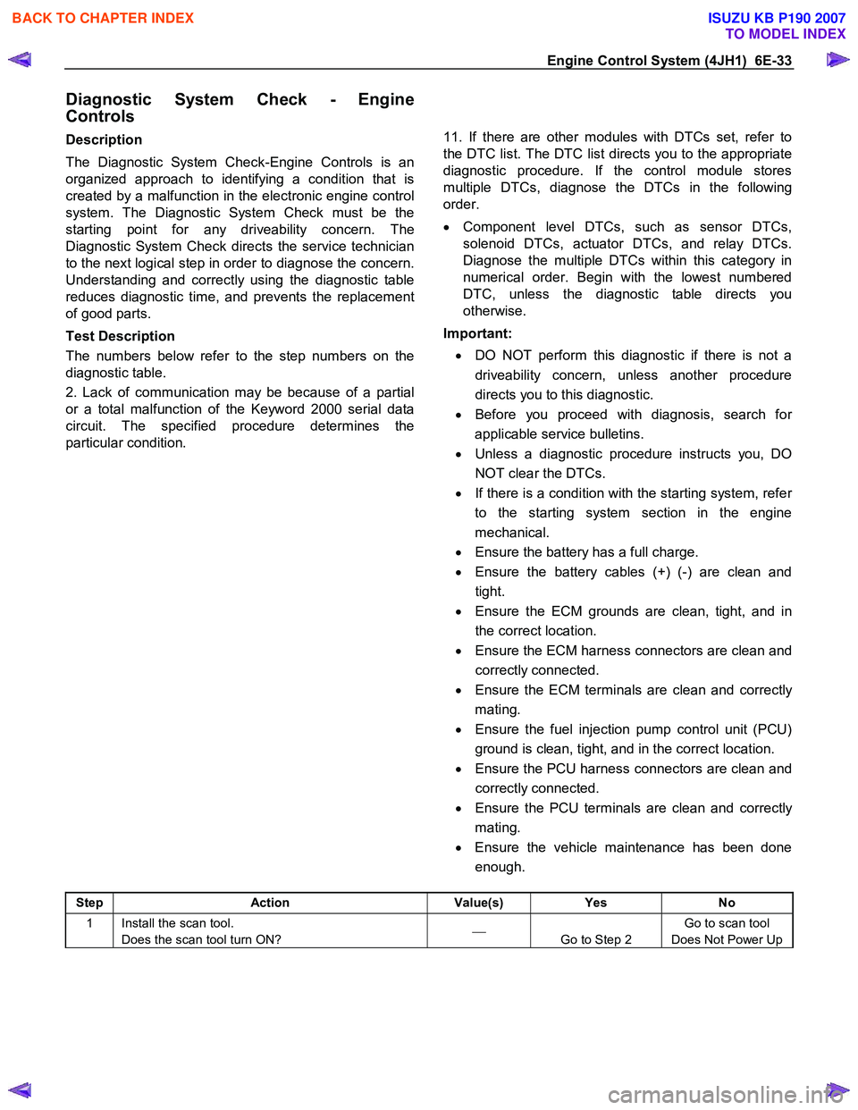
Diagnostic System Check - Engine
Controls
Description
The Diagnostic System Check-Engine Controls is an
organized approach to identifying a condition that is
created by a malfunction in the electronic engine control
system. The Diagnostic System Check must be the
starting point for any driveability concern. The
Diagnostic System Check directs the service technician
to the next logical step in order to diagnose the concern.
Understanding and correctly using the diagnostic table
reduces diagnostic time, and prevents the replacement
of good parts.
Test Description
The numbers below refer to the step numbers on the
diagnostic table.
2. Lack of communication may be because of a partial
or a total malfunction of the Keyword 2000 serial data
circuit. The specified procedure determines the
particular condition.
11. If there are other modules with DTCs set, refer to
the DTC list. The DTC list directs you to the appropriate
diagnostic procedure. If the control module stores
multiple DTCs, diagnose the DTCs in the following
order.
• Component level DTCs, such as sensor DTCs,
solenoid DTCs, actuator DTCs, and relay DTCs.
Diagnose the multiple DTCs within this category in
numerical order. Begin with the lowest numbered
DTC, unless the diagnostic table directs you
otherwise.
Important:
• DO NOT perform this diagnostic if there is not a
driveability concern, unless another procedure
directs you to this diagnostic.
• Before you proceed with diagnosis, search fo
r
applicable service bulletins.
• Unless a diagnostic procedure instructs you, DO
NOT clear the DTCs.
• If there is a condition with the starting system, refe
r
to the starting system section in the engine
mechanical.
• Ensure the battery has a full charge.
• Ensure the battery cables (+) (-) are clean and
tight.
• Ensure the ECM grounds are clean, tight, and in
the correct location.
• Ensure the ECM harness connectors are clean and
correctly connected.
• Ensure the ECM terminals are clean and correctl
y
mating.
• Ensure the fuel injection pump control unit (PCU)
ground is clean, tight, and in the correct location.
• Ensure the PCU harness connectors are clean and
correctly connected.
• Ensure the PCU terminals are clean and correctl
y
mating.
• Ensure the vehicle maintenance has been done
enough.
Step Action Value(s) Yes No
1 Install the scan tool.
Does the scan tool turn ON?
Go to Step 2 Go to scan tool
Does Not Power Up
BACK TO CHAPTER INDEX
TO MODEL INDEX
ISUZU KB P190 2007
Page 1079 of 6020
Engine Control System (4JH1) 6E-45
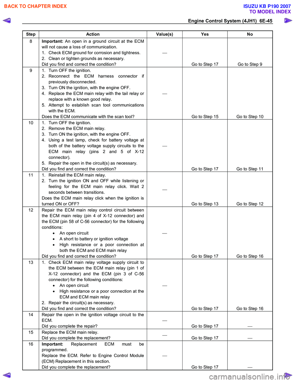
Step Action Value(s) Yes No
8 Important: An open in a ground circuit at the ECM
will not cause a loss of communication.
1. Check ECM ground for corrosion and tightness.
2. Clean or tighten grounds as necessary.
Did you find and correct the condition?
Go to Step 17 Go to Step 9
9 1. Turn OFF the ignition. 2. Reconnect the ECM harness connector if previously disconnected.
3. Turn ON the ignition, with the engine OFF.
4. Replace the ECM main relay with the tail relay or replace with a known good relay.
5. Attempt to establish scan tool communications with the ECM.
Does the ECM communicate with the scan tool?
Go to Step 15 Go to Step 10
10 1. Turn OFF the ignition. 2. Remove the ECM main relay.
3. Turn ON the ignition, with the engine OFF.
4. Using a test lamp, check for battery voltage at both of the battery voltage supply circuits to the
ECM main relay (pins 2 and 5 of X-12
connector).
5. Repair the open in the circuit(s) as necessary.
Did you find and correct the condition?
Go to Step 17 Go to Step 11
11 1. Reinstall the ECM main relay. 2. Turn the ignition ON and OFF while listening or feeling for the ECM main relay click. W ait 2
seconds between transitions.
Does the ECM main relay click when the ignition is
turned ON or OFF?
Go to Step 13 Go to Step 12
12 Repair the ECM main relay control circuit between the ECM main relay (pin 4 of X-12 connector) and
the ECM (pin 58 of C-56 connector) for the following
conditions: • An open circuit
• A short to battery or ignition voltage
• High resistance or a poor connection at
both the ECM and ECM main relay
Did you find and correct the condition?
Go to Step 17 Go to Step 16
13 1. Check ECM main relay voltage supply circuit to the ECM between the ECM main relay (pin 1 of
X-12 connector) and the ECM (pin 3 of C-56
connector) for the following conditions: • An open circuit
• High resistance or a poor connection at the
ECM and ECM main relay
2. Repair the circuit(s) as necessary.
Did you find and correct the condition?
Go to Step 17 Go to Step 16
14 Repair the open in the ignition voltage circuit to the ECM.
Did you complete the repair?
Go to Step 17
15 Replace the ECM main relay.
Did you complete the replacement?
Go to Step 17
16 Important: Replacement ECM must be
programmed.
Replace the ECM. Refer to Engine Control Module
(ECM) Replacement in this section.
Did you complete the replacement?
Go to Step 17
BACK TO CHAPTER INDEX
TO MODEL INDEX
ISUZU KB P190 2007
Page 1101 of 6020
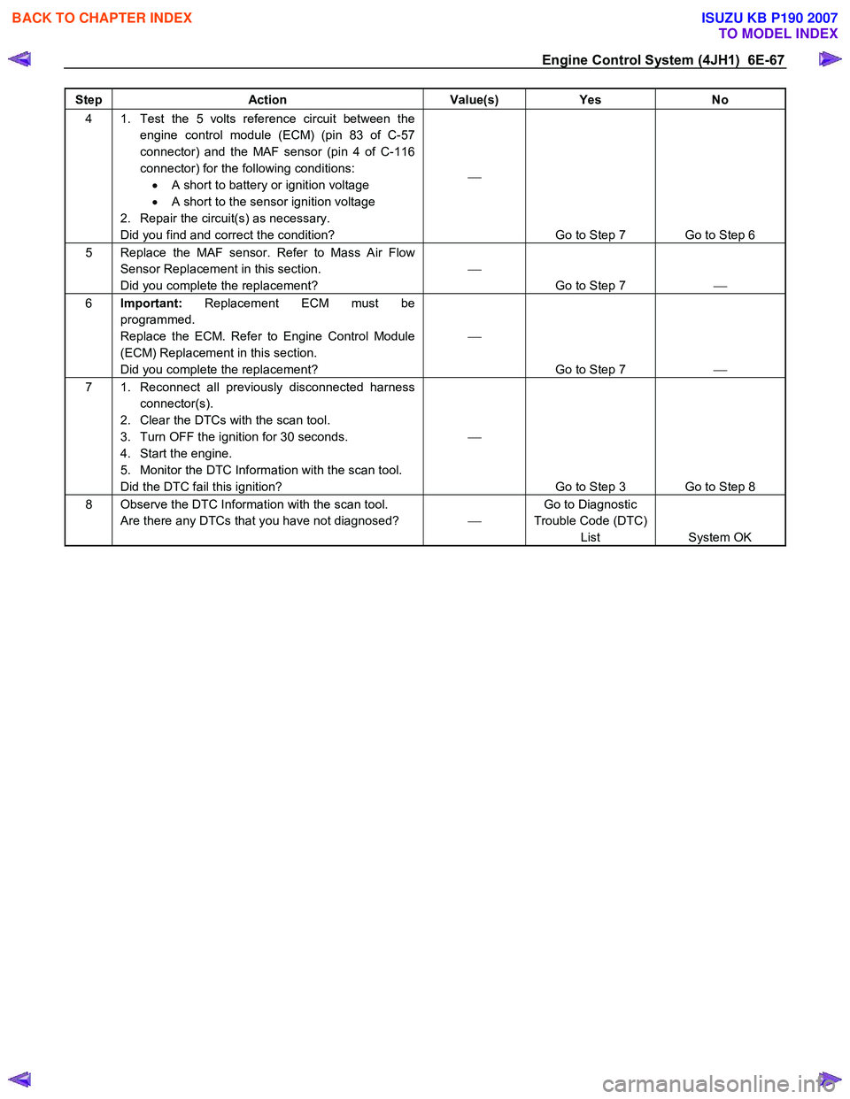
Engine Control System (4JH1) 6E-67
Step Action Value(s) Yes No
4 1. Test the 5 volts reference circuit between the
engine control module (ECM) (pin 83 of C-57
connector) and the MAF sensor (pin 4 of C-116
connector) for the following conditions: • A short to battery or ignition voltage
• A short to the sensor ignition voltage
2. Repair the circuit(s) as necessary.
Did you find and correct the condition?
Go to Step 7 Go to Step 6
5 Replace the MAF sensor. Refer to Mass Air Flow Sensor Replacement in this section.
Did you complete the replacement?
Go to Step 7
6 Important: Replacement ECM must be
programmed.
Replace the ECM. Refer to Engine Control Module
(ECM) Replacement in this section.
Did you complete the replacement?
Go to Step 7
7 1. Reconnect all previously disconnected harness
connector(s).
2. Clear the DTCs with the scan tool.
3. Turn OFF the ignition for 30 seconds.
4. Start the engine.
5. Monitor the DTC Information with the scan tool.
Did the DTC fail this ignition?
Go to Step 3 Go to Step 8
8 Observe the DTC Information with the scan tool. Are there any DTCs that you have not diagnosed? Go to Diagnostic
Trouble Code (DTC) List System OK
BACK TO CHAPTER INDEX
TO MODEL INDEX
ISUZU KB P190 2007
Page 1108 of 6020
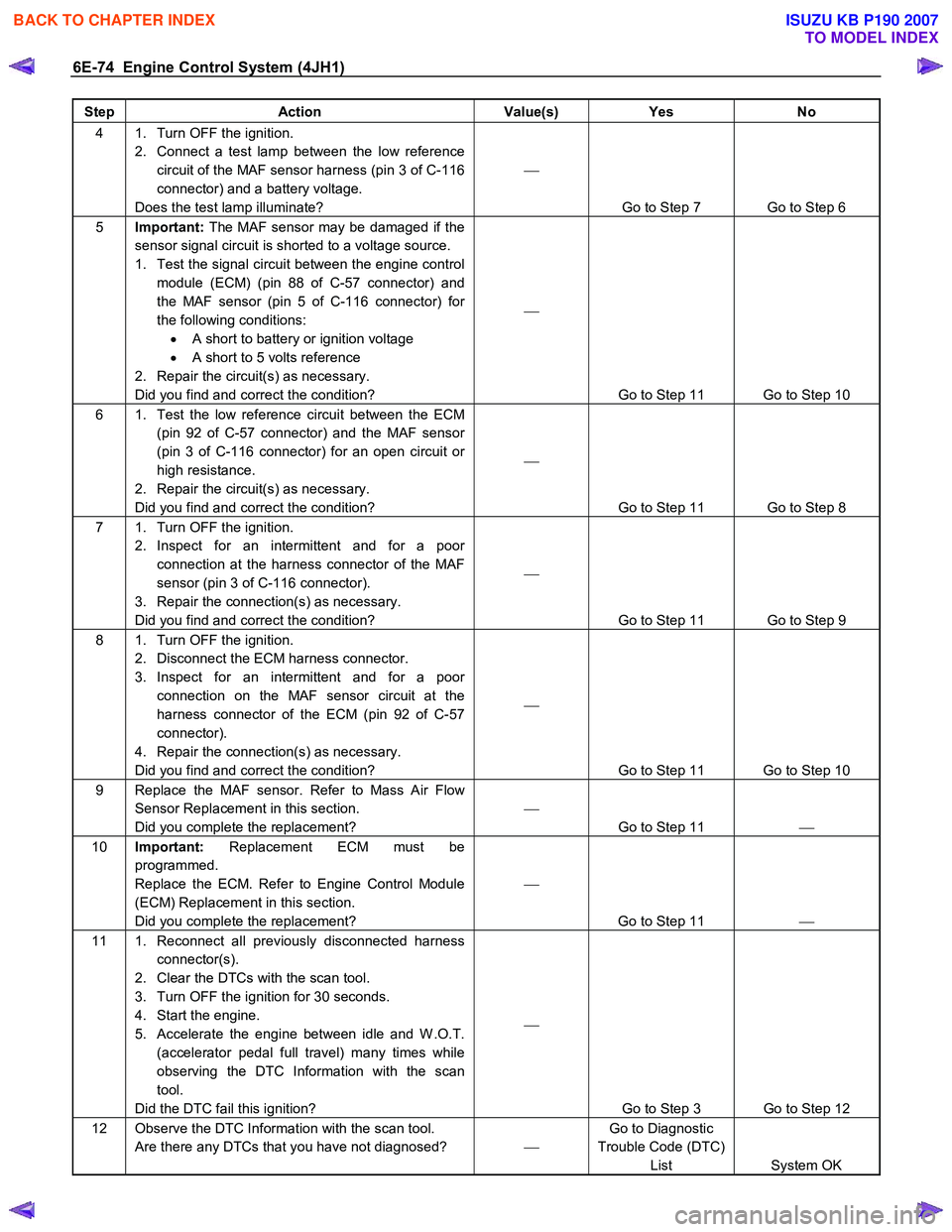
6E-74 Engine Control System (4JH1)
Step Action Value(s) Yes No
4 1. Turn OFF the ignition.
2. Connect a test lamp between the low reference circuit of the MAF sensor harness (pin 3 of C-116
connector) and a battery voltage.
Does the test lamp illuminate?
Go to Step 7 Go to Step 6
5 Important: The MAF sensor may be damaged if the
sensor signal circuit is shorted to a voltage source.
1. Test the signal circuit between the engine control module (ECM) (pin 88 of C-57 connector) and
the MAF sensor (pin 5 of C-116 connector) for
the following conditions: • A short to battery or ignition voltage
• A short to 5 volts reference
2. Repair the circuit(s) as necessary.
Did you find and correct the condition?
Go to Step 11 Go to Step 10
6 1. Test the low reference circuit between the ECM (pin 92 of C-57 connector) and the MAF sensor
(pin 3 of C-116 connector) for an open circuit or
high resistance.
2. Repair the circuit(s) as necessary.
Did you find and correct the condition?
Go to Step 11 Go to Step 8
7 1. Turn OFF the ignition. 2. Inspect for an intermittent and for a poor connection at the harness connector of the MAF
sensor (pin 3 of C-116 connector).
3. Repair the connection(s) as necessary.
Did you find and correct the condition?
Go to Step 11 Go to Step 9
8 1. Turn OFF the ignition. 2. Disconnect the ECM harness connector.
3. Inspect for an intermittent and for a poor connection on the MAF sensor circuit at the
harness connector of the ECM (pin 92 of C-57
connector).
4. Repair the connection(s) as necessary.
Did you find and correct the condition?
Go to Step 11 Go to Step 10
9 Replace the MAF sensor. Refer to Mass Air Flow Sensor Replacement in this section.
Did you complete the replacement?
Go to Step 11
10 Important: Replacement ECM must be
programmed.
Replace the ECM. Refer to Engine Control Module
(ECM) Replacement in this section.
Did you complete the replacement?
Go to Step 11
11 1. Reconnect all previously disconnected harness
connector(s).
2. Clear the DTCs with the scan tool.
3. Turn OFF the ignition for 30 seconds.
4. Start the engine.
5. Accelerate the engine between idle and W .O.T. (accelerator pedal full travel) many times while
observing the DTC Information with the scan
tool.
Did the DTC fail this ignition?
Go to Step 3 Go to Step 12
12 Observe the DTC Information with the scan tool. Are there any DTCs that you have not diagnosed? Go to Diagnostic
Trouble Code (DTC) List System OK
BACK TO CHAPTER INDEX
TO MODEL INDEX
ISUZU KB P190 2007
Page 1110 of 6020
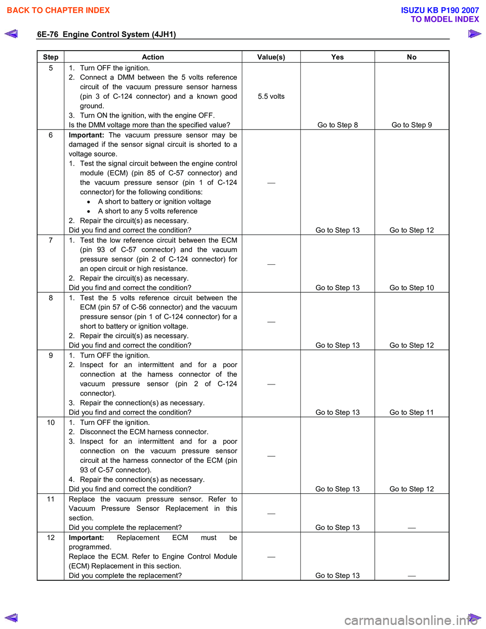
6E-76 Engine Control System (4JH1)
Step Action Value(s) Yes No
5 1. Turn OFF the ignition.
2. Connect a DMM between the 5 volts reference circuit of the vacuum pressure sensor harness
(pin 3 of C-124 connector) and a known good
ground.
3. Turn ON the ignition, with the engine OFF.
Is the DMM voltage more than the specified value? 5.5 volts
Go to Step 8 Go to Step 9
6 Important: The vacuum pressure sensor may be
damaged if the sensor signal circuit is shorted to a
voltage source.
1. Test the signal circuit between the engine control module (ECM) (pin 85 of C-57 connector) and
the vacuum pressure sensor (pin 1 of C-124
connector) for the following conditions: • A short to battery or ignition voltage
• A short to any 5 volts reference
2. Repair the circuit(s) as necessary.
Did you find and correct the condition?
Go to Step 13 Go to Step 12
7 1. Test the low reference circuit between the ECM (pin 93 of C-57 connector) and the vacuum
pressure sensor (pin 2 of C-124 connector) for
an open circuit or high resistance.
2. Repair the circuit(s) as necessary.
Did you find and correct the condition?
Go to Step 13 Go to Step 10
8 1. Test the 5 volts reference circuit between the ECM (pin 57 of C-56 connector) and the vacuum
pressure sensor (pin 1 of C-124 connector) for a
short to battery or ignition voltage.
2. Repair the circuit(s) as necessary.
Did you find and correct the condition?
Go to Step 13 Go to Step 12
9 1. Turn OFF the ignition. 2. Inspect for an intermittent and for a poor connection at the harness connector of the
vacuum pressure sensor (pin 2 of C-124
connector).
3. Repair the connection(s) as necessary.
Did you find and correct the condition?
Go to Step 13 Go to Step 11
10 1. Turn OFF the ignition. 2. Disconnect the ECM harness connector.
3. Inspect for an intermittent and for a poor connection on the vacuum pressure sensor
circuit at the harness connector of the ECM (pin
93 of C-57 connector).
4. Repair the connection(s) as necessary.
Did you find and correct the condition?
Go to Step 13 Go to Step 12
11 Replace the vacuum pressure sensor. Refer to Vacuum Pressure Sensor Replacement in this
section.
Did you complete the replacement?
Go to Step 13
12 Important: Replacement ECM must be
programmed.
Replace the ECM. Refer to Engine Control Module
(ECM) Replacement in this section.
Did you complete the replacement?
Go to Step 13
BACK TO CHAPTER INDEX
TO MODEL INDEX
ISUZU KB P190 2007
Page 1115 of 6020
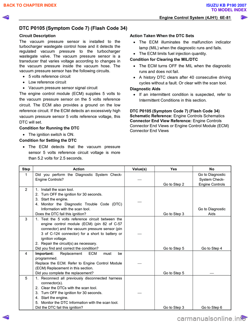
Engine Control System (4JH1) 6E-81
DTC P0105 (Symptom Code 7) (Flash Code 34)
Circuit Description
The vacuum pressure sensor is installed to the
turbocharger wastegate control hose and it detects the
regulated vacuum pressure to the turbocharge
r
wastegate valve. The vacuum pressure sensor is a
transducer that varies voltage according to changes in
the vacuum pressure inside the vacuum hose. The
vacuum pressure sensor has the following circuits.
• 5 volts reference circuit
• Low reference circuit
• Vacuum pressure sensor signal circuit
The engine control module (ECM) supplies 5 volts to
the vacuum pressure sensor on the 5 volts reference
circuit. The ECM also provides a ground on the lo
w
reference circuit. If the ECM detects an excessively high
vacuum pressure sensor 5 volts reference voltage, this
DTC will set.
Condition for Running the DTC
• The ignition switch is ON.
Condition for Setting the DTC
• The ECM detects that the vacuum pressure
sensor 5 volts reference circuit voltage is more
than 5.2 volts for 2.5 seconds.
Action Taken When the DTC Sets
• The ECM illuminates the malfunction indicato
r
lamp (MIL) when the diagnostic runs and fails.
• The ECM limits fuel injection quantity.
Condition for Clearing the MIL/DTC
• The ECM turns OFF the MIL when the diagnostic
runs and does not fail.
• A history DTC clears after 40 consecutive driving
cycles without a fault. Or clear with the scan tool.
Diagnostic Aids
• If an intermittent condition is suspected, refer to
Intermittent Conditions in this section.
DTC P0105 (Symptom Code 7) (Flash Code 34)
Schematic Reference: Engine Controls Schematics
Connector End View Reference: Engine Controls
Connector End Views or Engine Control Module (ECM)
Connector End Views
Step Action Value(s) Yes No
1 Did you perform the Diagnostic System Check-
Engine Controls?
Go to Step 2 Go to Diagnostic
System Check-
Engine Controls
2 1. Install the scan tool. 2. Turn OFF the ignition for 30 seconds.
3. Start the engine.
4. Monitor the Diagnostic Trouble Code (DTC) Information with the scan tool.
Does the DTC fail this ignition?
Go to Step 3 Go to Diagnostic
Aids
3 1. Test the 5 volts reference circuit between the engine control module (ECM) (pin 82 of C-57
connector) and the vacuum pressure sensor (pin
3 of C-124 connector) for a short to battery or
ignition voltage.
2. Repair the circuit(s) as necessary.
Did you find and correct the condition?
Go to Step 5 Go to Step 4
4 Important: Replacement ECM must be
programmed.
Replace the ECM. Refer to Engine Control Module
(ECM) Replacement in this section.
Did you complete the replacement?
Go to Step 5
5 1. Reconnect all previously disconnected harness
connector(s).
2. Clear the DTCs with the scan tool.
3. Turn OFF the ignition for 30 seconds.
4. Start the engine.
5. Monitor the DTC Information with the scan tool.
Did the DTC fail this ignition?
Go to Step 3 Go to Step 6
BACK TO CHAPTER INDEX
TO MODEL INDEX
ISUZU KB P190 2007
Page 1133 of 6020
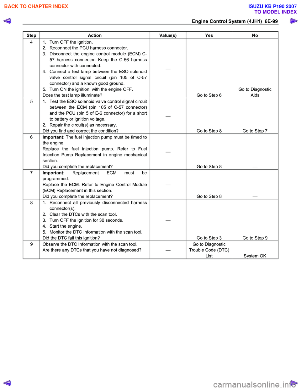
Engine Control System (4JH1) 6E-99
Step Action Value(s) Yes No
4 1. Turn OFF the ignition.
2. Reconnect the PCU harness connector.
3. Disconnect the engine control module (ECM) C- 57 harness connector. Keep the C-56 harness
connector with connected.
4. Connect a test lamp between the ESO solenoid valve control signal circuit (pin 105 of C-57
connector) and a known good ground.
5. Turn ON the ignition, with the engine OFF.
Does the test lamp illuminate?
Go to Step 6 Go to Diagnostic
Aids
5 1. Test the ESO solenoid valve control signal circuit between the ECM (pin 105 of C-57 connector)
and the PCU (pin 5 of E-6 connector) for a short
to battery or ignition voltage.
2. Repair the circuit(s) as necessary.
Did you find and correct the condition?
Go to Step 8 Go to Step 7
6 Important: The fuel injection pump must be timed to
the engine.
Replace the fuel injection pump. Refer to Fuel
Injection Pump Replacement in engine mechanical
section.
Did you complete the replacement?
Go to Step 8
7 Important: Replacement ECM must be
programmed.
Replace the ECM. Refer to Engine Control Module
(ECM) Replacement in this section.
Did you complete the replacement?
Go to Step 8
8 1. Reconnect all previously disconnected harness
connector(s).
2. Clear the DTCs with the scan tool.
3. Turn OFF the ignition for 30 seconds.
4. Start the engine.
5. Monitor the DTC Information with the scan tool.
Did the DTC fail this ignition?
Go to Step 3 Go to Step 9
9 Observe the DTC Information with the scan tool. Are there any DTCs that you have not diagnosed? Go to Diagnostic
Trouble Code (DTC) List System OK
BACK TO CHAPTER INDEX
TO MODEL INDEX
ISUZU KB P190 2007
Page 1146 of 6020
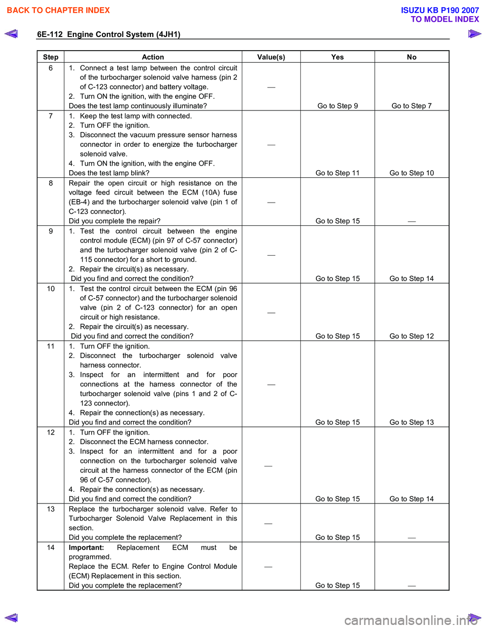
6E-112 Engine Control System (4JH1)
Step Action Value(s) Yes No
6 1. Connect a test lamp between the control circuit
of the turbocharger solenoid valve harness (pin 2
of C-123 connector) and battery voltage.
2. Turn ON the ignition, with the engine OFF.
Does the test lamp continuously illuminate?
Go to Step 9 Go to Step 7
7 1. Keep the test lamp with connected. 2. Turn OFF the ignition.
3. Disconnect the vacuum pressure sensor harness connector in order to energize the turbocharger
solenoid valve.
4. Turn ON the ignition, with the engine OFF.
Does the test lamp blink?
Go to Step 11 Go to Step 10
8 Repair the open circuit or high resistance on the voltage feed circuit between the ECM (10A) fuse
(EB-4) and the turbocharger solenoid valve (pin 1 of
C-123 connector).
Did you complete the repair?
Go to Step 15
9 1. Test the control circuit between the engine
control module (ECM) (pin 97 of C-57 connector)
and the turbocharger solenoid valve (pin 2 of C-
115 connector) for a short to ground.
2. Repair the circuit(s) as necessary.
Did you find and correct the condition?
Go to Step 15 Go to Step 14
10 1. Test the control circuit between the ECM (pin 96 of C-57 connector) and the turbocharger solenoid
valve (pin 2 of C-123 connector) for an open
circuit or high resistance.
2. Repair the circuit(s) as necessary.
Did you find and correct the condition?
Go to Step 15 Go to Step 12
11 1. Turn OFF the ignition. 2. Disconnect the turbocharger solenoid valve harness connector.
3. Inspect for an intermittent and for poor connections at the harness connector of the
turbocharger solenoid valve (pins 1 and 2 of C-
123 connector).
4. Repair the connection(s) as necessary.
Did you find and correct the condition?
Go to Step 15 Go to Step 13
12 1. Turn OFF the ignition. 2. Disconnect the ECM harness connector.
3. Inspect for an intermittent and for a poor connection on the turbocharger solenoid valve
circuit at the harness connector of the ECM (pin
96 of C-57 connector).
4. Repair the connection(s) as necessary.
Did you find and correct the condition?
Go to Step 15 Go to Step 14
13 Replace the turbocharger solenoid valve. Refer to Turbocharger Solenoid Valve Replacement in this
section.
Did you complete the replacement?
Go to Step 15
14 Important: Replacement ECM must be
programmed.
Replace the ECM. Refer to Engine Control Module
(ECM) Replacement in this section.
Did you complete the replacement?
Go to Step 15
BACK TO CHAPTER INDEX
TO MODEL INDEX
ISUZU KB P190 2007