Circuit ISUZU KB P190 2007 Workshop Repair Manual
[x] Cancel search | Manufacturer: ISUZU, Model Year: 2007, Model line: KB P190, Model: ISUZU KB P190 2007Pages: 6020, PDF Size: 70.23 MB
Page 5611 of 6020
9-6 ACCESSORIES
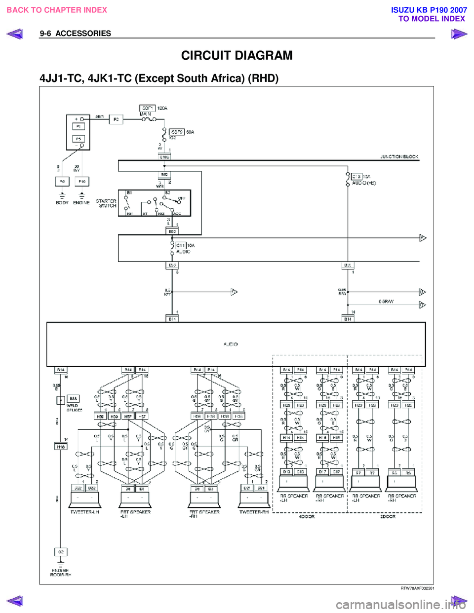
CIRCUIT DIAGRAM
4JJ1-TC, 4JK1-TC (Except South Africa) (RHD)
RTW 78AXF032301
BACK TO CHAPTER INDEX
TO MODEL INDEXISUZU KB P190 2007
Page 5636 of 6020
SUPPLEMENTAL RESTRAINT SYSTEM 9A-1
SECTION 9A
SUPPLEMENTAL RESTRAINT SYSTEM (SRS)
TABLE OF CONTENTS
PAGE
Service Precaution ....................................................................................................... 9A- 4
General Description...................................................................................................... 9A- 4 Restraint Devices ..................................................................................................... 9A- 4
System Description .................................................................................................. 9A- 5
Circuit Diagram ............................................................................................................. 9A- 6
SRS Component And Wiring Location View .............................................................. 9A- 10
Component Description ............................................................................................... 9A- 14 SRS Control Unit ...................................................................................................... 9A- 14
"SRS" Warning Lamp .............................................................................................. 9A- 14
SRS Coil Assembly .................................................................................................. 9A- 15
Air Bag Assemblies.................................................................................................. 9A- 15
Steering Column ...................................................................................................... 9A- 16
Knee Bolster ............................................................................................................. 9A- 16
Definitions .................................................................................................................... . 9A- 16
Diagnosis...................................................................................................................... . 9A- 18
Diagnostic Trouble Codes ....................................................................................... 9A- 18
Scan Tool Diagnostics............................................................................................. 9A- 18
Use Of Special Tools ............................................................................................... 9A- 18
SRS Connec tor Body Face Vie ws ............................................................................. ..9 A- 19
Repairs And Inspec tions Required After A n A ccident ............................................ ..9 A- 20
Accident With Deployment-Component Replacement And Inspections ............. 9A- 20
Accident With or Without Deployment-Component Inspection ........................... 9A- 20
SRS Control Unit Replacement Guidelines ........................................................... 9A- 20
Wiring Damage ......................................................................................................... 9A- 20
SRS Connector (Plastic Body And Terminal Metal Pin) Damage ......................... 9A- 20
SRS Wire Pigtail Damage ........................................................................................ 9A- 20
PAGE 1 OF 3
BACK TO CHAPTER INDEX TO MODEL INDEXISUZU KB P190 2007
Page 5641 of 6020
9A-6 SUPPLEMENTAL RESTRAINT SYSTEM
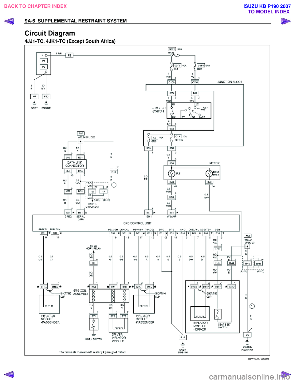
Circuit Diagram
4JJ1-TC, 4JK1-TC (Except South Africa)
RTW 78AXF028601
BACK TO CHAPTER INDEX
TO MODEL INDEXISUZU KB P190 2007
Page 5650 of 6020
SUPPLEMENTAL RESTRAINT SYSTEM 9A-15
RTW 79ASH000501
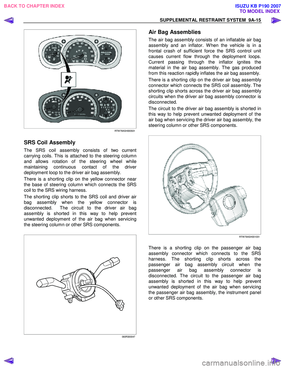
SRS Coil Assembly
The SRS coil assembly consists of two current
carrying coils. This is attached to the steering column
and allows rotation of the steering wheel while
maintaining continuous contact of the drive
r
deployment loop to the driver air bag assembly.
There is a shorting clip on the yellow connector nea
r
the base of steering column which connects the SRS
coil to the SRS wiring harness.
The shorting clip shorts to the SRS coil and driver ai
r
bag assembly when the yellow connector is
disconnected. The circuit to the driver air bag
assembly is shorted in this way to help prevent
unwanted deployment of the air bag when servicing
the steering column or other SRS components.
060R300047
Air Bag Assemblies
The air bag assembly consists of an inflatable air bag
assembly and an inflator. W hen the vehicle is in a
frontal crash of sufficient force the SRS control unit
causes current flow through the deployment loops.
Current passing through the inflator ignites the
material in the air bag assembly. The gas produced
from this reaction rapidly inflates the air bag assembly.
There is a shorting clip on the driver air bag assembl
y
connector which connects the SRS coil assembly. The
shorting clip shorts across the driver air bag assembl
y
circuits when the driver air bag assembly connector is
disconnected.
The circuit to the driver air bag assembly is shorted in
this way to help prevent unwanted deployment of the
air bag when servicing the driver air bag assembly, the
steering column or other SRS components.
RTW 79ASH001001
There is a shorting clip on the passenger air bag
assembly connector which connects to the SRS
harness. The shorting clip shorts across the
passenger air bag assembly circuit when the
passenger air bag assembly connector is
disconnected. The circuit to the passenger air bag
assembly is shorted in this way to help prevent
unwanted deployment of the air bag when servicing
the passenger air bag assembly, the instrument panel
or other SRS components.
BACK TO CHAPTER INDEX TO MODEL INDEXISUZU KB P190 2007
Page 5651 of 6020
9A-16 SUPPLEMENTAL RESTRAINT SYSTEM
RTW 79ASH000201
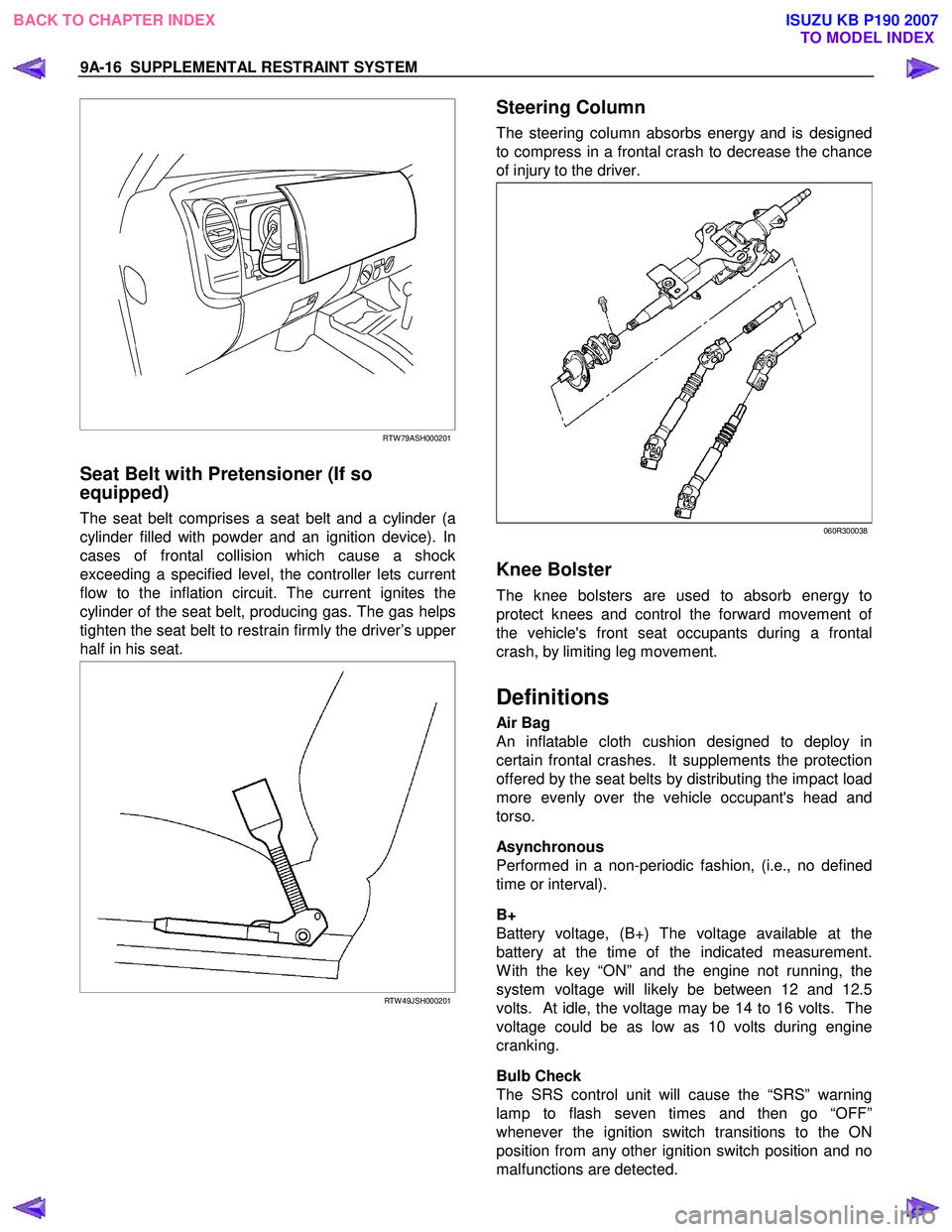
Seat Belt with Pretensioner (If so
equipped)
The seat belt comprises a seat belt and a cylinder (a
cylinder filled with powder and an ignition device). In
cases of frontal collision which cause a shock
exceeding a specified level, the controller lets current
flow to the inflation circuit. The current ignites the
cylinder of the seat belt, producing gas. The gas helps
tighten the seat belt to restrain firmly the driver’s uppe
r
half in his seat.
RTW 49JSH000201
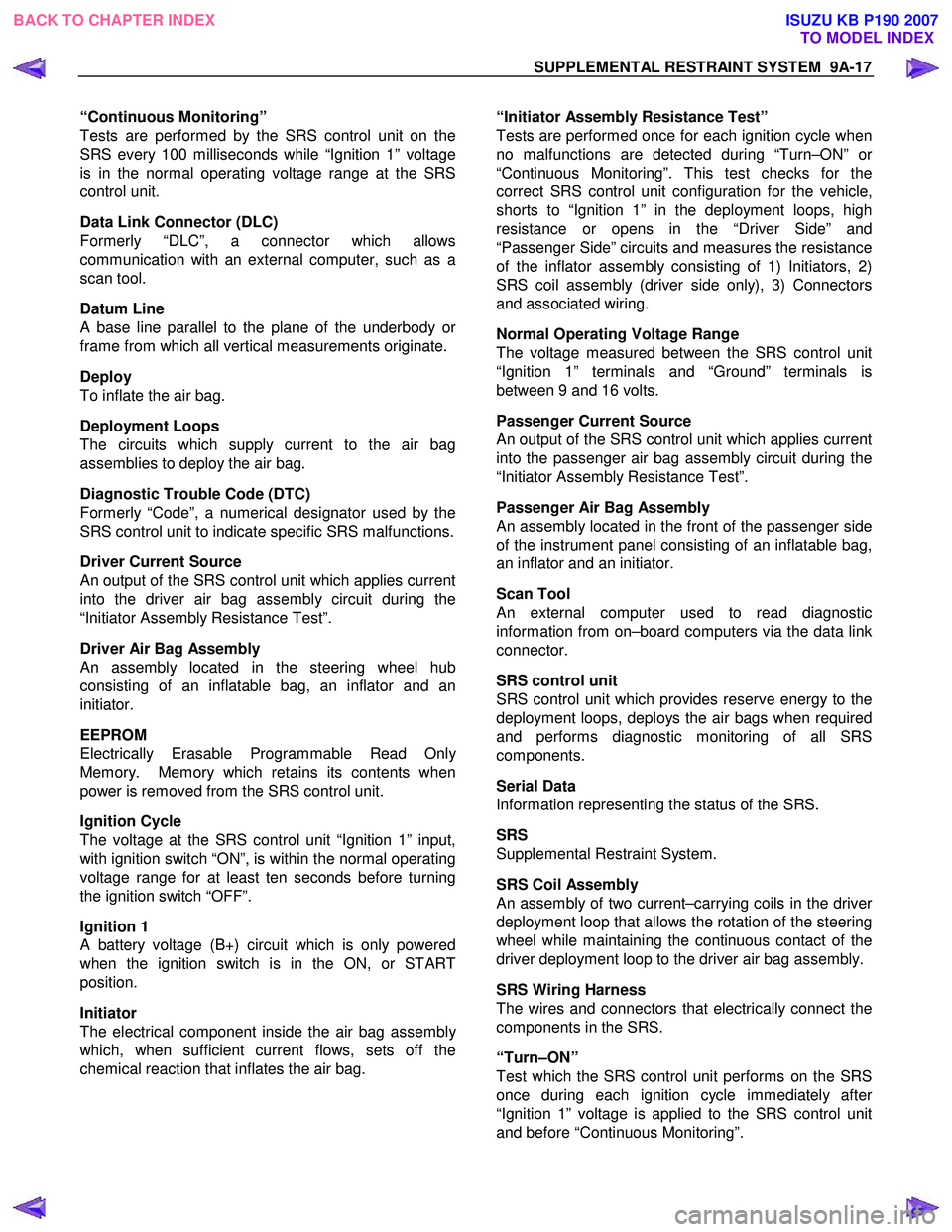
Steering Column
The steering column absorbs energy and is designed
to compress in a frontal crash to decrease the chance
of injury to the driver.
060R300038
Knee Bolster
The knee bolsters are used to absorb energy to
protect knees and control the forward movement o
f
the vehicle's front seat occupants during a frontal
crash, by limiting leg movement.
Definitions
Air Bag
An inflatable cloth cushion designed to deploy in
certain frontal crashes. It supplements the protection
offered by the seat belts by distributing the impact load
more evenly over the vehicle occupant's head and
torso.
Asynchronous
Performed in a non-periodic fashion, (i.e., no defined
time or interval).
B+
Battery voltage, (B+) The voltage available at the
battery at the time of the indicated measurement.
W ith the key “ON” and the engine not running, the
system voltage will likely be between 12 and 12.5
volts. At idle, the voltage may be 14 to 16 volts. The
voltage could be as low as 10 volts during engine
cranking.
Bulb Check
The SRS control unit will cause the “SRS” warning
lamp to flash seven times and then go “OFF”
whenever the ignition switch transitions to the ON
position from any other ignition switch position and no
malfunctions are detected.
BACK TO CHAPTER INDEX TO MODEL INDEXISUZU KB P190 2007
Page 5652 of 6020
SUPPLEMENTAL RESTRAINT SYSTEM 9A-17
“Continuous Monitoring”
Tests are performed by the SRS control unit on the
SRS every 100 milliseconds while “Ignition 1” voltage
is in the normal operating voltage range at the SRS
control unit.
Data Link Connector (DLC)
Formerly “DLC”, a connector which allows
communication with an external computer, such as a
scan tool.
Datum Line
A base line parallel to the plane of the underbody or
frame from which all vertical measurements originate.
Deploy
To inflate the air bag.
Deployment Loops
The circuits which supply current to the air bag
assemblies to deploy the air bag.
Diagnostic Trouble Code (DTC)
Formerly “Code”, a numerical designator used by the
SRS control unit to indicate specific SRS malfunctions.
Driver Current Source
An output of the SRS control unit which applies current
into the driver air bag assembly circuit during the
“Initiator Assembly Resistance Test”.
Driver Air Bag Assembly
An assembly located in the steering wheel hub
consisting of an inflatable bag, an inflator and an
initiator.
EEPROM
Electrically Erasable Programmable Read Onl
y
Memory. Memory which retains its contents when
power is removed from the SRS control unit.
Ignition Cycle
The voltage at the SRS control unit “Ignition 1” input,
with ignition switch “ON”, is within the normal operating
voltage range for at least ten seconds before turning
the ignition switch “OFF”.
Ignition 1
A battery voltage (B+) circuit which is only powered
when the ignition switch is in the ON, or START
position.
Initiator
The electrical component inside the air bag assembl
y
which, when sufficient current flows, sets off the
chemical reaction that inflates the air bag.
“Initiator Assembly Resistance Test”
Tests are performed once for each ignition cycle when
no malfunctions are detected during “Turn–ON” o
r
“Continuous Monitoring”. This test checks for the
correct SRS control unit configuration for the vehicle,
shorts to “Ignition 1” in the deployment loops, high
resistance or opens in the “Driver Side” and
“Passenger Side” circuits and measures the resistance
of the inflator assembly consisting of 1) Initiators, 2)
SRS coil assembly (driver side only), 3) Connectors
and associated wiring.
Normal Operating Voltage Range
The voltage measured between the SRS control unit
“Ignition 1” terminals and “Ground” terminals is
between 9 and 16 volts.
Passenger Current Source
An output of the SRS control unit which applies current
into the passenger air bag assembly circuit during the
“Initiator Assembly Resistance Test”.
Passenger Air Bag Assembly
An assembly located in the front of the passenger side
of the instrument panel consisting of an inflatable bag,
an inflator and an initiator.
Scan Tool
An external computer used to read diagnostic
information from on–board computers via the data link
connector.
SRS control unit
SRS control unit which provides reserve energy to the
deployment loops, deploys the air bags when required
and performs diagnostic monitoring of all SRS
components.
Serial Data
Information representing the status of the SRS.
SRS
Supplemental Restraint System.
SRS Coil Assembly
An assembly of two current–carrying coils in the drive
r
deployment loop that allows the rotation of the steering
wheel while maintaining the continuous contact of the
driver deployment loop to the driver air bag assembly.
SRS Wiring Harness
The wires and connectors that electrically connect the
components in the SRS.
“Turn–ON”
Test which the SRS control unit performs on the SRS
once during each ignition cycle immediately afte
r
“Ignition 1” voltage is applied to the SRS control unit
and before “Continuous Monitoring”.
BACK TO CHAPTER INDEX TO MODEL INDEXISUZU KB P190 2007
Page 5662 of 6020
SUPPLEMENTAL RESTRAINT SYSTEM 9A-27
5. Remove the passenger air bag assembly from the
vehicle. Refer to “Passenger Air Bag Assembl
y
Removal “.
6. Clear a space on the ground approximately 183 cm (six feet) in diameter where the fixture with
attached air bag assembly is to be placed fo
r
deployment. A paved outdoor location where there
is no activity is preferred. If an outdoor location is
not available, a space on the shop floor where
there is no activity and there is sufficient ventilation
is recommended. Ensure that no loose o
r
flammable objects are within the deployment area.
7. Place the 5-8840-2420-0 on the bench vise. This is necessary to provide sufficient stabilization o
f
the fixture during deployment.
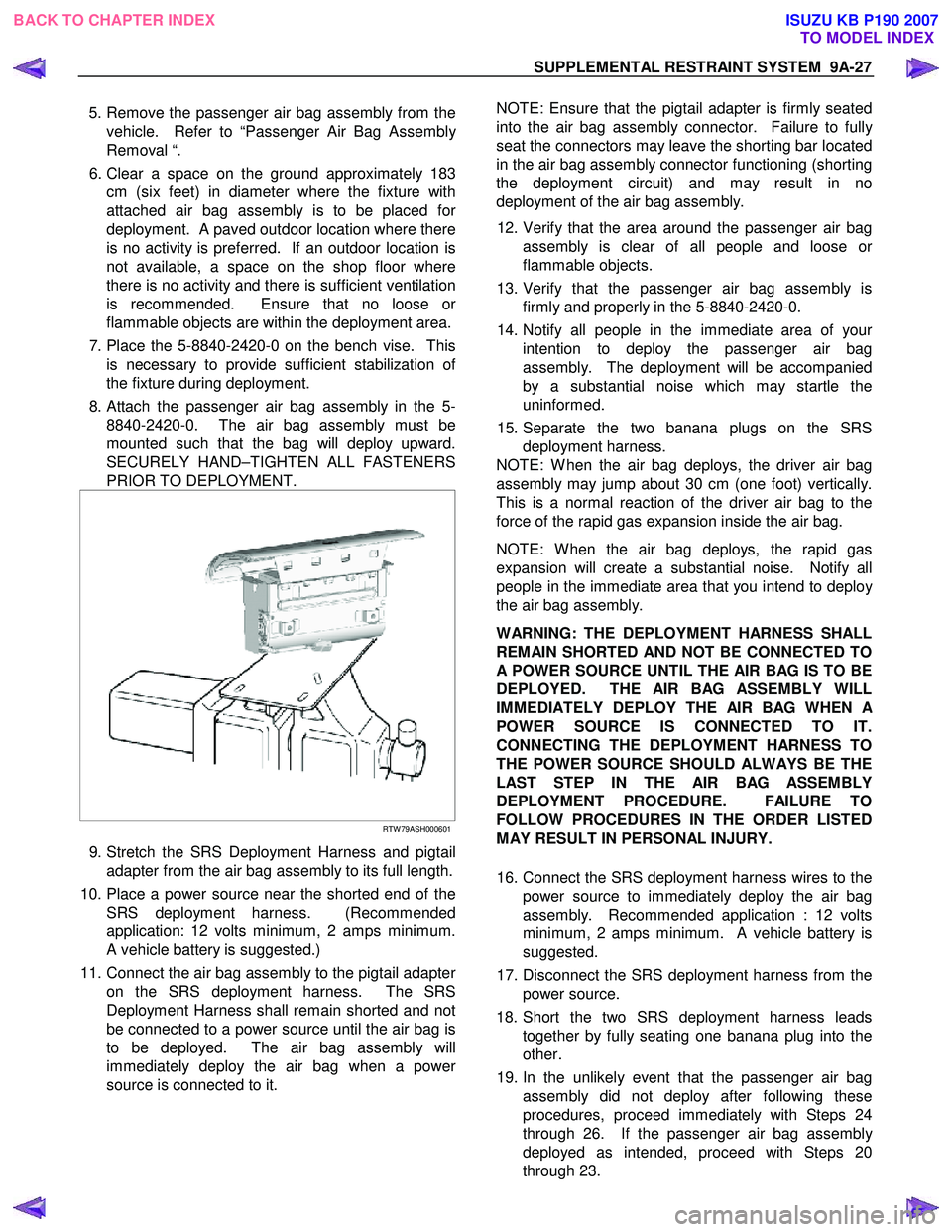
8. Attach the passenger air bag assembly in the 5- 8840-2420-0. The air bag assembly must be
mounted such that the bag will deploy upward.
SECURELY HAND–TIGHTEN ALL FASTENERS
PRIOR TO DEPLOYMENT.
RTW 79ASH000601
9. Stretch the SRS Deployment Harness and pigtail
adapter from the air bag assembly to its full length.
10. Place a power source near the shorted end of the SRS deployment harness. (Recommended
application: 12 volts minimum, 2 amps minimum.
A vehicle battery is suggested.)
11. Connect the air bag assembly to the pigtail adapte
r
on the SRS deployment harness. The SRS
Deployment Harness shall remain shorted and not
be connected to a power source until the air bag is
to be deployed. The air bag assembly will
immediately deploy the air bag when a powe
r
source is connected to it.
NOTE: Ensure that the pigtail adapter is firmly seated
into the air bag assembly connector. Failure to full
y
seat the connectors may leave the shorting bar located
in the air bag assembly connector functioning (shorting
the deployment circuit) and may result in no
deployment of the air bag assembly.
12. Verify that the area around the passenger air bag assembly is clear of all people and loose o
r
flammable objects.
13. Verify that the passenger air bag assembly is firmly and properly in the 5-8840-2420-0.
14. Notify all people in the immediate area of you
r
intention to deploy the passenger air bag
assembly. The deployment will be accompanied
by a substantial noise which may startle the
uninformed.
15. Separate the two banana plugs on the SRS deployment harness.
NOTE: W hen the air bag deploys, the driver air bag
assembly may jump about 30 cm (one foot) vertically.
This is a normal reaction of the driver air bag to the
force of the rapid gas expansion inside the air bag.
NOTE: W hen the air bag deploys, the rapid gas
expansion will create a substantial noise. Notify all
people in the immediate area that you intend to deplo
y
the air bag assembly.
WARNING: THE DEPLOYMENT HARNESS SHALL
REMAIN SHORTED AND NOT BE CONNECTED TO
A POWER SOURCE UNTIL THE AIR BAG IS TO BE
DEPLOYED. THE AIR BAG ASSEMBLY WILL
IMMEDIATELY DEPLOY THE AIR BAG WHEN
A
POWER SOURCE IS CONNECTED TO IT.
CONNECTING THE DEPLOYMENT HARNESS TO
THE POWER SOURCE SHOULD ALWAYS BE THE
LAST STEP IN THE AIR BAG ASSEMBLY
DEPLOYMENT PROCEDURE. FAILURE TO
FOLLOW PROCEDURES IN THE ORDER LISTED
MAY RESULT IN PERSONAL INJURY.
16. Connect the SRS deployment harness wires to the power source to immediately deploy the air bag
assembly. Recommended application : 12 volts
minimum, 2 amps minimum. A vehicle battery is
suggested.
17. Disconnect the SRS deployment harness from the power source.
18. Short the two SRS deployment harness leads together by fully seating one banana plug into the
other.
19. In the unlikely event that the passenger air bag assembly did not deploy after following these
procedures, proceed immediately with Steps 24
through 26. If the passenger air bag assembl
y
deployed as intended, proceed with Steps 20
through 23.
BACK TO CHAPTER INDEX TO MODEL INDEXISUZU KB P190 2007
Page 5668 of 6020
SUPPLEMENTAL RESTRAINT SYSTEM 9A-33
Inspections Required After An Accident
CAUTION: Certain SRS components must be
replaced after a frontal crash involving air bag
deployment.
In all types of accidents regardless of “Air Bag”
deployment, visually inspect all of the following
components and replace as required:
– Driver air bag assembly
– Passenger air bag assembly
– Steering wheel
– SRS coil assembly
– Steering column
– Knee bolster and instrument panel mounting attachments
– Driver seat and belt
– Passenger seat and belt
– SRS control unit
The SRS control unit should always be checked
according to “SRS Control Unit Replacement
Guidelines.”
CAUTION: Refer to “SRS control unit Replacement
Guidelines” below for important information on
SRS control unit replacement in both deployment
and non–deployment crashes.
Inspect the SRS coil assembly wiring and the steering
wheel for any sign of scorching, melting, or damage
due to excessive heat. If the coil assembly wire o
r
steering wheel is damaged, replace them. The
steering column and wheel must be dimensionall
y
checked to determine if they are damaged. Refer to
“steering wheel” in this manual.
Never use SRS parts from another vehicle. This does
not include remanufactured parts purchased from an
authorized ISUZU/GM Retailer; they may be used fo
r
SRS repairs.
Do not attempt to repair the SRS control unit, the SRS
harness, the SRS coil assembly, the air bag assembly,
the steering wheel, or the steering column. Service o
f
these items is replacement only. Verify replacement
part numbers.
CAUTION: Proper operation of the SRS control
unit and the supplemental restraint system (SRS)
requires that any repairs to the vehicle structure
return it to its original production configuration.
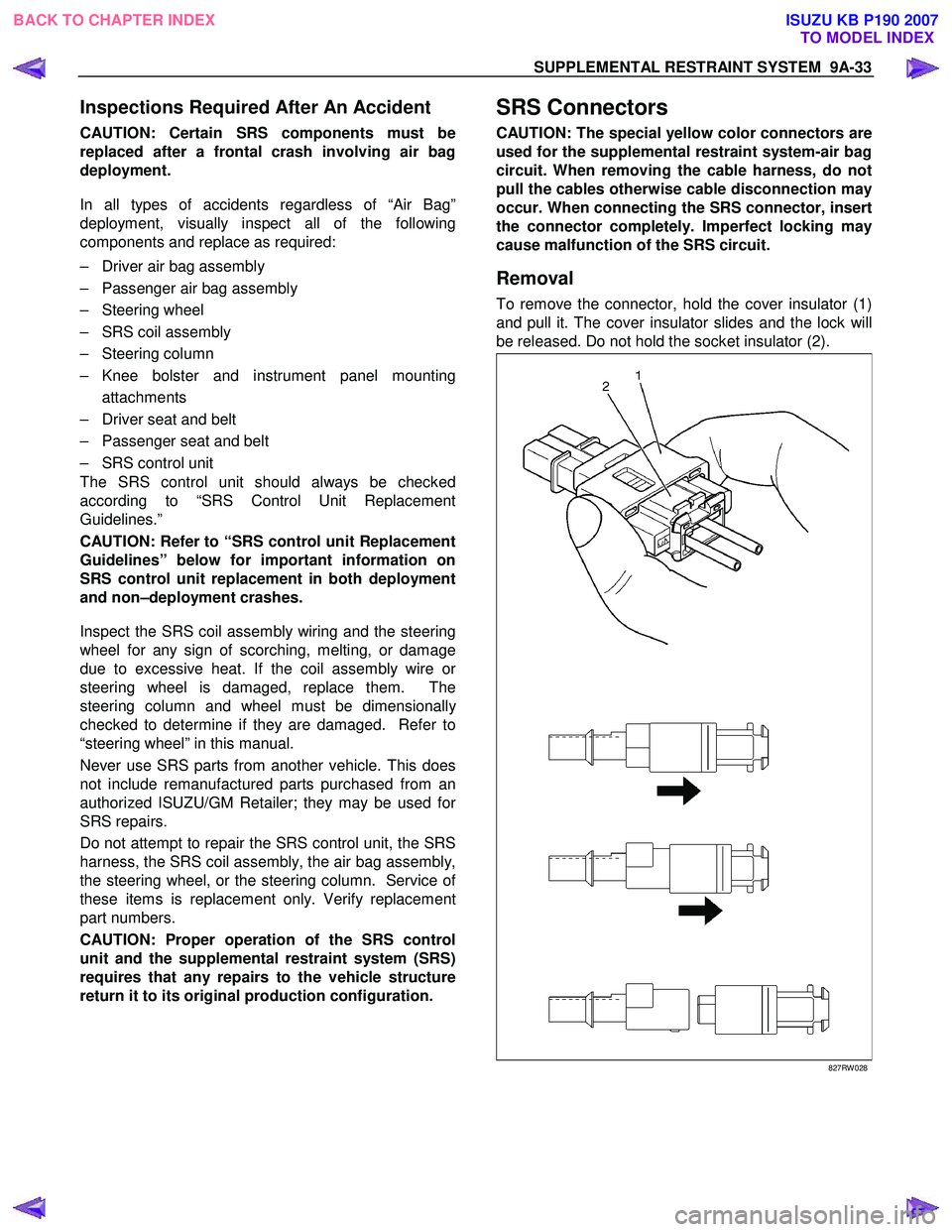
SRS Connectors
CAUTION: The special yellow color connectors are
used for the supplemental restraint system-air bag
circuit. When removing the cable harness, do not
pull the cables otherwise cable disconnection may
occur. When connecting the SRS connector, insert
the connector completely. Imperfect locking may
cause malfunction of the SRS circuit.
Removal
To remove the connector, hold the cover insulator (1)
and pull it. The cover insulator slides and the lock will
be released. Do not hold the socket insulator (2).
827RW 028
BACK TO CHAPTER INDEX TO MODEL INDEXISUZU KB P190 2007
Page 5680 of 6020
SUPPLEMENTAL RESTRAINT SYSTEM 9A-45
Special Tools
WARNING: TO AVOID DEPLOYMENT WHEN
TROUBLESHOOTING THE SRS, DO NOT USE
ELECTRICAL TEST EQUIPMENT SUCH AS
A
BATTERY–POWERED OR AC–POWERED
VOLTMETER, OHMMETER, ETC., OR ANY TYPE
OF ELECTRICAL EQUIPMENT OTHER THAN THAT
SPECIFIED IN THIS MANUAL. DO NOT USE AN
UNPOWERED PROBE–TYPE TESTER.
INSTRUCTIONS IN THIS MANUAL MUST BE
FOLLOWED CAREFULLY, OTHERWISE
PERSONAL INJURY MAY RESULT.
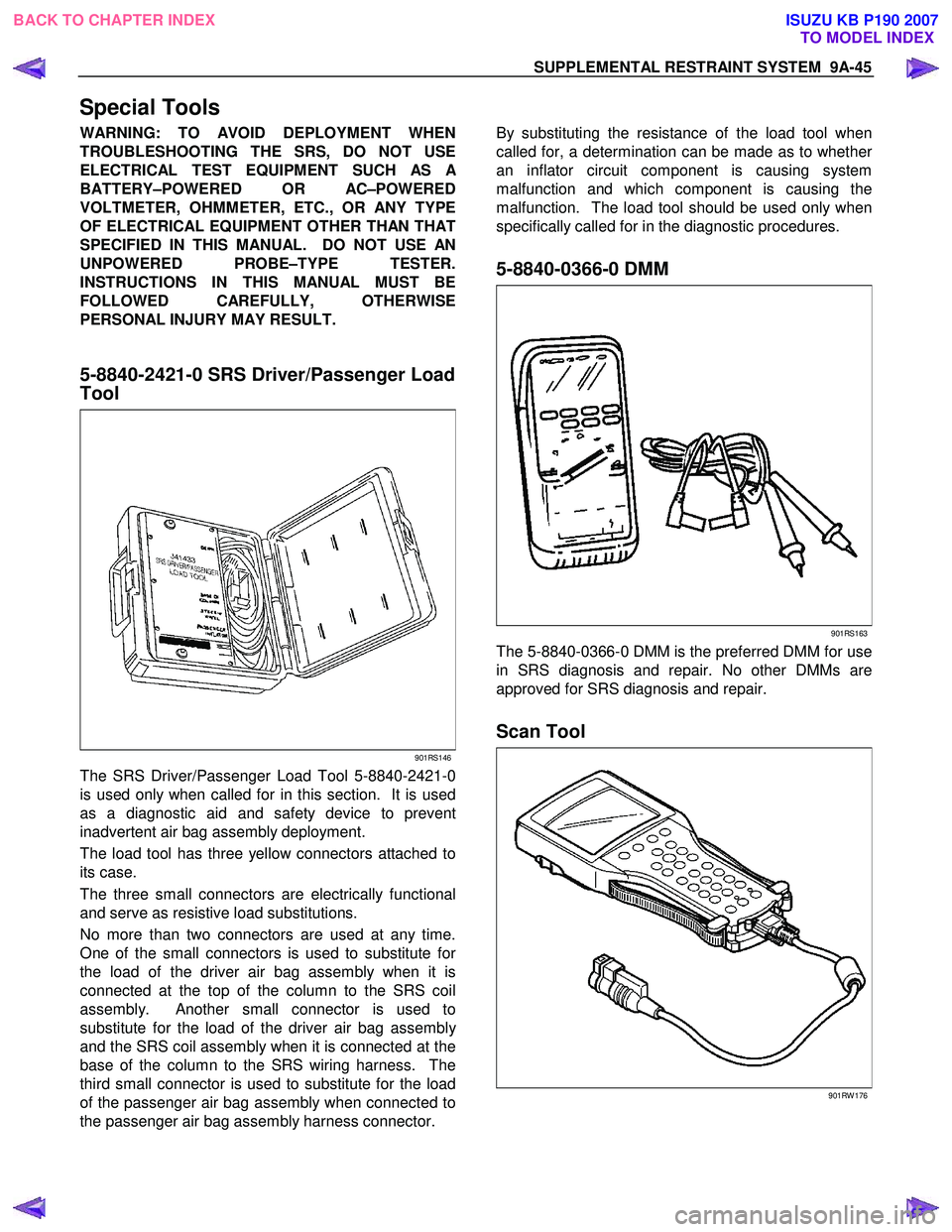
5-8840-2421-0 SRS Driver/Passenger Load
Tool
901RS146
The SRS Driver/Passenger Load Tool 5-8840-2421-0
is used only when called for in this section. It is used
as a diagnostic aid and safety device to prevent
inadvertent air bag assembly deployment.
The load tool has three yellow connectors attached to
its case.
The three small connectors are electrically functional
and serve as resistive load substitutions.
No more than two connectors are used at any time.
One of the small connectors is used to substitute fo
r
the load of the driver air bag assembly when it is
connected at the top of the column to the SRS coil
assembly. Another small connector is used to
substitute for the load of the driver air bag assembl
y
and the SRS coil assembly when it is connected at the
base of the column to the SRS wiring harness. The
third small connector is used to substitute for the load
of the passenger air bag assembly when connected to
the passenger air bag assembly harness connector.
By substituting the resistance of the load tool when
called for, a determination can be made as to whethe
r
an inflator circuit component is causing system
malfunction and which component is causing the
malfunction. The load tool should be used only when
specifically called for in the diagnostic procedures.
5-8840-0366-0 DMM
901RS163
The 5-8840-0366-0 DMM is the preferred DMM for use
in SRS diagnosis and repair. No other DMMs are
approved for SRS diagnosis and repair.
Scan Tool
901RW 176
BACK TO CHAPTER INDEX TO MODEL INDEXISUZU KB P190 2007
Page 5683 of 6020
RESTRAINT CONTROL SYSTEM 9A1-1
SECTION 9A1
RESTRAINT CONTROL SYSTEM
TABLE OF CONTENTS
PAGE
Service Precaution ............................................................................................................. ..........9A1- 2
Diagnosis In formation ......................................................................................................... ........9A1- 3
Diagnostic Procedures .......................................................................................................... ......9A1- 3
Diagnostic Codes ............................................................................................................... ..........9A1- 3
How To Read Trouble Codes ..................................................................................................... .9A1- 3
How To Clear Trouble Codes .................................................................................................... ..9A1- 3
Scan Tool Di agnostics .......................................................................................................... .......9A1- 3
Basic Knowledge Required ....................................................................................................... ..9A1- 4
Basic Electrical Circuits ..................................................................................................... .........9A1- 4
"Flash Code" Diagnostics ...................................................................................................... ....9A1- 4
DATA LIST (Tech2) .............................................................................................................. .........9A1- 5
Diagnostic Trouble Codes ....................................................................................................... ....9A1- 6
System Schematic .............................................................................................................. .........9A 1- 7
SRS Diagnostic System Check ...................................................................................................9 A1- 7
Chart A SRS control uni t Integrity Check...................................................................................9A1- 10
Chart B "SRS" Warning Lamp Comes "ON" Steady..................................................................9A1- 12
Chart C "SRS" Warning Lamp Does Not Come "ON" Steady ..................................................9A1-14
DTC B0015 (Flash Code 15) Passenger Air Ba g Squib Circuit High Resistance ...................9A1-17
DTC B0016 (Flash Code 16) Passenger Air Ba g Squib Circuit Low Resistance .....................9A1-20
DTC B0018 (Flash Code 18) Passenger Air Ba g Squib Circuit Short to GND.........................9A1-23
DTC B0019 (Flash Code 19) Passenger Air Bag Squib Circuit Short to Battery
Voltage ........................................................................................................................ ..................9A1- 26
DTC B0021 (Flash Code 21) Driver Air Ba g Squib Circuit High Resistance ............................9A1-28
DTC B0022 (Flash Code 22) Driver Air Ba g Squib Circuit Low Resistance.............................9A1-31
DTC B0025 (Flash Code 25) Driver Air Ba g Squib Circuit Short to GND ................................9A1-34
DTC B0026 (Flash Code 26) Driver Air Bag Squib Circuit Short to Battery
Voltage ........................................................................................................................ ..................9A1- 37
BACK TO CHAPTER INDEX
TO MODEL INDEX
ISUZU KB P190 2007