Circuit ISUZU KB P190 2007 Workshop Repair Manual
[x] Cancel search | Manufacturer: ISUZU, Model Year: 2007, Model line: KB P190, Model: ISUZU KB P190 2007Pages: 6020, PDF Size: 70.23 MB
Page 5950 of 6020

11A-52 IMMOBILIZER SYSTEM (C24SE, 4JA1-T)
B0016 FREQUENCY SIGNAL HIGH (Only 4JA1-L Engine)
Step Action Value(s) Yes No
1
W as the "Immobilizer System Check" performed?
Go to Step 2 Go to Immobilizer
System Check
2 Recheck the DTC.
1. Key position is “OFF”.
2. Install the scan tool on vehicle.
3. Key position is “ON”.
4. Check the DTC on scan tool.
Is DTC B0016 stored?
Go to Step 3 Refer to
Diagnostic Aids
3 Check the immobilizer communication W line circuit.
1. Key position is “OFF”.
2. Disconnect the immobilizer control unit (ICU).
3. Disconnect the engine control module (Engine immobilizer unit).
4. Check the immobilizer communication W line circuit for an open, short to ground, or short to
voltage.
Also, check the ICU and Engine immobilizer unit
ignition feed circuits for an open or short to ground
and the ICU and Engine immobilizer unit ground
circuit for an open.
W as a problem found?
Go to Step 4 Go to Step 5
4 Repair or replace the immobilizer communication W
line circuit.
W as the action complete?
Verify repair
5 Replace the immobilizer control unit (ICU).
IMPORTANT: The replacement ICU must be
programmed the security data by scan tool.
W as the action complete?
Verify repair
BACK TO CHAPTER INDEX
TO MODEL INDEX
ISUZU KB P190 2007
Page 5951 of 6020

IMMOBILIZER SYSTEM (C24SE, 4JA1-T) 11A-53
B0023 IMMOBILIZER COIL CIRCUIT (ANTENNA COIL FAULT)
(Only 4JA1-T Engine)
Step Action Value(s) Yes No
1
W as the "Immobilizer System Check" performed?
Go to Step 2 Go to Immobilizer
System Check
2 Check the immobilizer coil (antenna) circuit.
1. Key position is “OFF”.
2. Disconnect the immobilizer control unit (ICU).
(immobilizer coil circuit : 3 pin connector)
3. Check the immobilizer coil circuit for an open, short to ground, or short to voltage.
Also, check the ICU ignition feed circuit for an open or
short to ground and the ICU ground circuit for an
open.
W as a problem found?
Go to Step 3 Go to Step 4
3 Repair or replace the immobilizer coil (antenna).
W as the action complete?
Verify repair
4 Recheck the DTC.
1. Key position is “OFF” and keep the position for more than 30 seconds.
2. Key position is “ON”.
3. Check the DTC on scan tool.
Is DTC B0023 stored?
Go to Step 5 Verify repair
5 Replace the immobilizer control unit (ICU).
IMPORTANT: The replacement ICU must be
programmed the security data by scan tool.
W as the action complete?
Verify repair
BACK TO CHAPTER INDEX
TO MODEL INDEX
ISUZU KB P190 2007
Page 5953 of 6020

IMMOBILIZER SYSTEM (C24SE, 4JA1-T) 11A-55
B0055 EEPROM ERROR
Step Action Value(s) Yes No
1
W as the "Immobilizer System Check" performed?
Go to Step 2 Go to Immobilizer
System Check
2 Recheck the DTC.
1. Key position is “OFF”.
2. Install the scan tool on vehicle.
3. Key position is “ON”.
4. Check the DTC on scan tool.
Is DTC B0055 stored?
Go to Step 3 Refer to
Diagnostic Aids
3 Check the immobilizer control unit (ICU) circuit.
1. Ignition "OFF," disconnect the ICU.
2. Check the ICU circuit for an open, short to ground, or short to voltage.
Also, check the ICU ignition feed circuit for an open or
short to ground and the ICU ground circuit for an
open.
W as a problem found?
Go to Step 4 Go to Step 5
4 Repair or replace the immobilizer unit (ICU) circuit.
W as the action complete?
Verify repair
5 Replace the immobilizer control unit (ICU).
IMPORTANT: The replacement ICU must be
programmed the security data by scan tool.
W as the action complete?
Verify repair
BACK TO CHAPTER INDEX TO MODEL INDEX
ISUZU KB P190 2007
Page 5955 of 6020

ANTITHEFT SYSTEM 11B-1
SECTION 11B
ANTITHEFT SYSTEM
TABLE OF CONTENTS
Service Precaution .................................................. 11B- 2
General Description ................................................ 11B- 2
Diagrams And Schematics ................................. 11B- 5 System W iring Diagrams ................................ 11B- 5
Parts Location ................................................. 11B- 6
Circuit Diagram ..............................................11B-10
Antitheft control unit (A) ...................................11B-24
Pin-outs ...........................................................11B-24
Pin-Assignment ...............................................11B-25
lmportant information on Programming..............11B-26
Tech-2 Scan Tool ...............................................11B-27 Operating Procedure .......................................11B-27
Menu ...............................................................11B-28
DTC .................................................................11B-28
Clear DTC Information ....................................11B-28
Tech-2 Data Display........................................11B-28
Actuator Test ...................................................11B-28
Programming...................................................11B-30
Tech-2 Data List ..............................................11B-35
Diagnosis............................................................11B-36 Diagnostic procedure ......................................11B-36
Clearing Diagnostic Trouble Codes ................11B-36
Verifying Vehicle Repair ..................................11B-36
Diagnostic Aids................................................11B-36
Diagnostic Trouble Code (DTC) list
For Antitheft.....................................................11B-37
Antitheft System Check ...................................11B-38
No Antitheft Lamp ...........................................11B-39
DTC13 Security code not yet programmed .....11B-40
DTC14 No remote key programmed ...............11B-41
DTC16 Door lock actuators short circuit
to ground .........................................................11B-42
DTC20 Broken wire to door lock actuators .....11B-43
DTC21 Remote key 1 with random code
out of capture range ........................................11B-44
DTC22 Remote key 2 with random code
out of capture range ........................................11B-45
DTC23 Remote key 3 with random code
out of capture range ........................................11B-46
DTC24 Remote key 4 with random code
out of capture range ........................................ 11B-47
DTC25 Remote key 5 with random code
out of capture range ........................................ 11B-48
DTC28 Input immobilizer short circuit
to ground ......................................................... 11B-49
DTC29 Broken wire to immobilizer ................. 11B-50
DTC31 Actuator driver door defect ................. 11B-51
DTC32 Actuator passenger door defect ......... 11B-52
DTC36 Broken wire to driver door................... 11B-53
DTC37 Broken wire to passenger door........... 11B-54
DTC41 Driver door Lock switch unlock
defect .............................................................. 11B-55
DTC42 Driver door Lock switch lock defect .... 11B-56
DTC43 Driver door Lock switch Super lock
defect .............................................................. 11B-57
DTC44 Passenger door Lock switch lock
defect .............................................................. 11B-58
DTC45 Passenger door Lock switch unlock
defect .............................................................. 11B-59
DTC47 Battery voltage for door lock actuators
is missing ........................................................ 11B-60
DTC50 A/D converter defect or battery
voltage less than 9 volt.................................... 11B-61
DTC51 EEPROM defect ................................. 11B-62
DTC52 EEPROM not programmed
by ISUZU ......................................................... 11B-63
DTC55 Control unit defect............................... 11B-64
DTC123 Output flasher short circuit to ground
or broken wire ................................................. 11B-65
DTC125 Output alarm horn broken wire ......... 11B-66
BACK TO CHAPTER INDEX TO MODEL INDEX
ISUZU KB P190 2007
Page 5957 of 6020

ANTITHEFT SYSTEM 11B-3
Function of a keyless entry system
W ith a keyless entry system the car can be locked or
unlocked from any position around the car up to a
specified distance, by using the potable radio remote
transmitter inside key (remote key).
Status LED
W hile the system is in delay the alarm system is active
and LED flashes at 0.5Hz with or without activated
interior protection.
Hazard relay
The hazard warning lights will be activated by an
external relay. The output is low active.
Switches
All switches to ground. This makes it possible for failure
analysis to detect a short circuit or a broken wire to
each switch. To use this feature it is necessary to place
a 1.8k Ω resistor in parallel to the required switch.
Receiver
The receiver is integrated into the control unit.
To lower the idle current the receiver is equipped with a
standby mode. The antenna is integrated on the printed
circuit board.
Depending on the mounting position of the control unit
the antenna can be connected externally.
Range of communication
The range of communication between remote key and
receiver is intended to be least 3 m from centre of the
car.
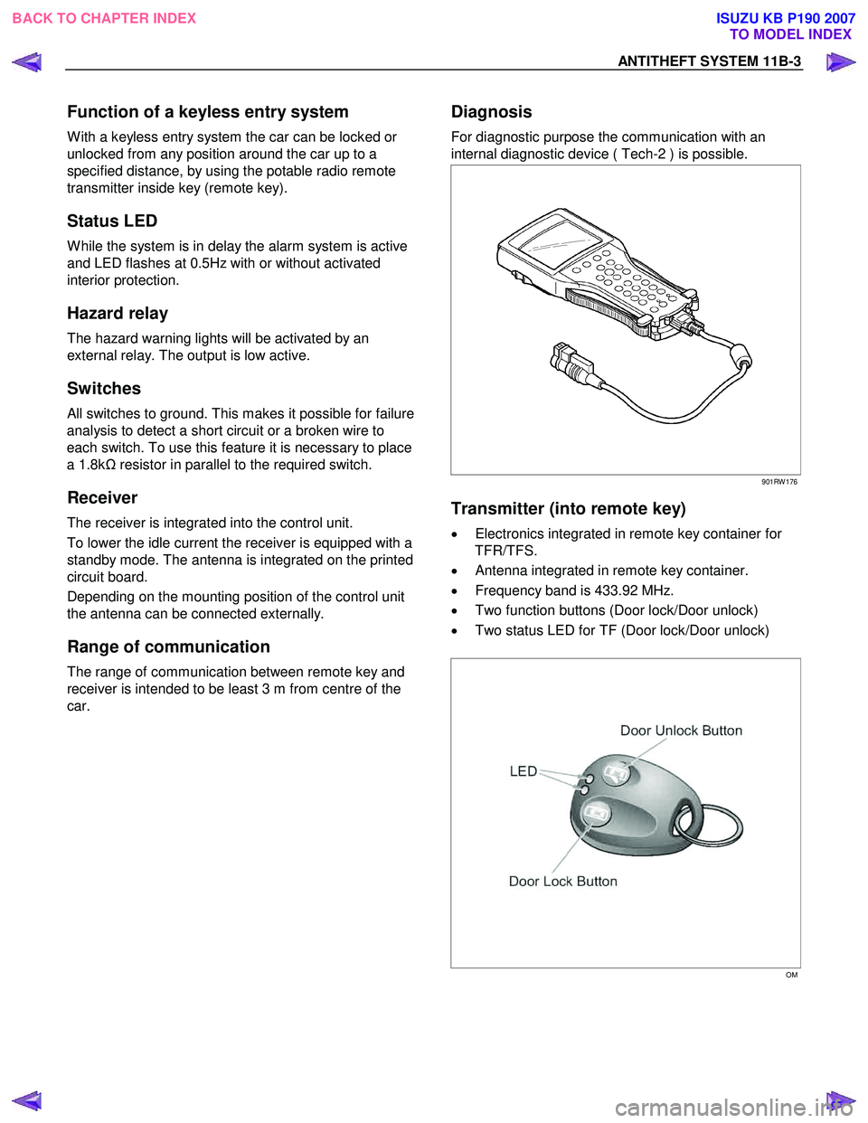
Diagnosis
For diagnostic purpose the communication with an
internal diagnostic device ( Tech-2 ) is possible.
901RW 176
Transmitter (into remote key)
• Electronics integrated in remote key container for
TFR/TFS.
• Antenna integrated in remote key container.
• Frequency band is 433.92 MHz.
• Two function buttons (Door lock/Door unlock)
• Two status LED for TF (Door lock/Door unlock)
OM
BACK TO CHAPTER INDEX TO MODEL INDEX
ISUZU KB P190 2007
Page 5964 of 6020

11B-10 ANTITHEFT SYSTEM
Circuit Diagram
4JJ1-TC, 4JK1-TC (except South Africa) (RHD)
RTW 78AXF033901
BACK TO CHAPTER INDEX
TO MODEL INDEX
ISUZU KB P190 2007
Page 5983 of 6020

ANTITHEFT SYSTEM 11B-29
Arm/Disarm Signal Test
Arm/Disarm signal test is used to check abnormalities
in arm/disarm signal circuit.
1. Select “Body” and “Antitheft”.
2. Select “Actuator Test” and “
Arm/Disarm Signal
Test”.
3. Observe the data list.
4. Insert the key into door key cylinder.
5. Remove the key into door key cylinder.
RAW 4B0SH000201
Horn Signal Test
Horn signal test is used to check abnormalities in horn
signal circuit.
1. Select “Body” and “Antitheft”.
2. Select “Actuator Test” and “Horn Signal Test”.
3. Observe the alarm sound.
4. Push “active bottom”.
5. Check the alarm sound function.
RAW 4B0SH000301
Turn Signal Test
Turn signal test is used to check abnormalities in turn
signal circuit.
1. Select “Body” and “Antitheft”.
2. Select “Actuator Test” and “Turn Signal Test”.
3. Observe the flasher lamp.
4. Push “active bottom”.
5. Check the flasher lamp function.
RAW 4B0SH000401
Theft LED Test
Theft LED test is used to check abnormalities in theft
LED signal circuit.
1. Select “Body” and “Antitheft”.
2. Select “Actuator Test” and “Turn Signal Test”.
3. Observe the antitheft LED.
4. Push “active bottom”.
5. Check the antitheft function.
RAW 4B0SH000501
BACK TO CHAPTER INDEX
TO MODEL INDEX
ISUZU KB P190 2007
Page 5991 of 6020

ANTITHEFT SYSTEM 11B-37
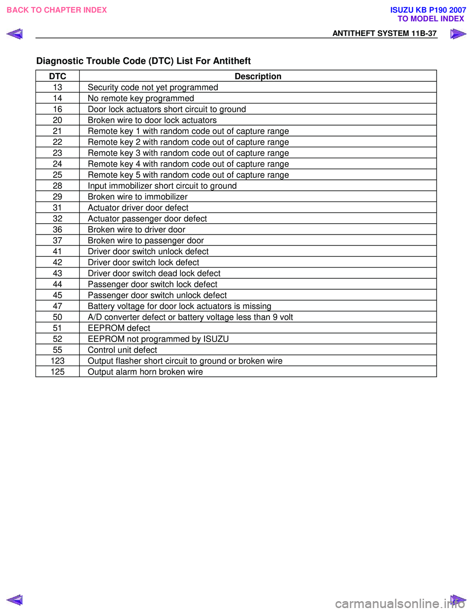
Diagnostic Trouble Code (DTC) List For Antitheft
DTC Description
13 Security code not yet programmed
14 No remote key programmed
16 Door lock actuators short circuit to ground
20 Broken wire to door lock actuators
21 Remote key 1 with random code out of capture range
22 Remote key 2 with random code out of capture range
23 Remote key 3 with random code out of capture range
24 Remote key 4 with random code out of capture range
25 Remote key 5 with random code out of capture range
28 Input immobilizer short circuit to ground
29 Broken wire to immobilizer
31 Actuator driver door defect
32 Actuator passenger door defect
36 Broken wire to driver door
37 Broken wire to passenger door
41 Driver door switch unlock defect
42 Driver door switch lock defect
43 Driver door switch dead lock defect
44 Passenger door switch lock defect
45 Passenger door switch unlock defect
47 Battery voltage for door lock actuators is missing
50 A/D converter defect or battery voltage less than 9 volt
51 EEPROM defect
52 EEPROM not programmed by ISUZU
55 Control unit defect
123 Output flasher short circuit to ground or broken wire
125 Output alarm horn broken wire
BACK TO CHAPTER INDEX TO MODEL INDEX
ISUZU KB P190 2007
Page 5992 of 6020

11B-38 ANTITHEFT SYSTEM
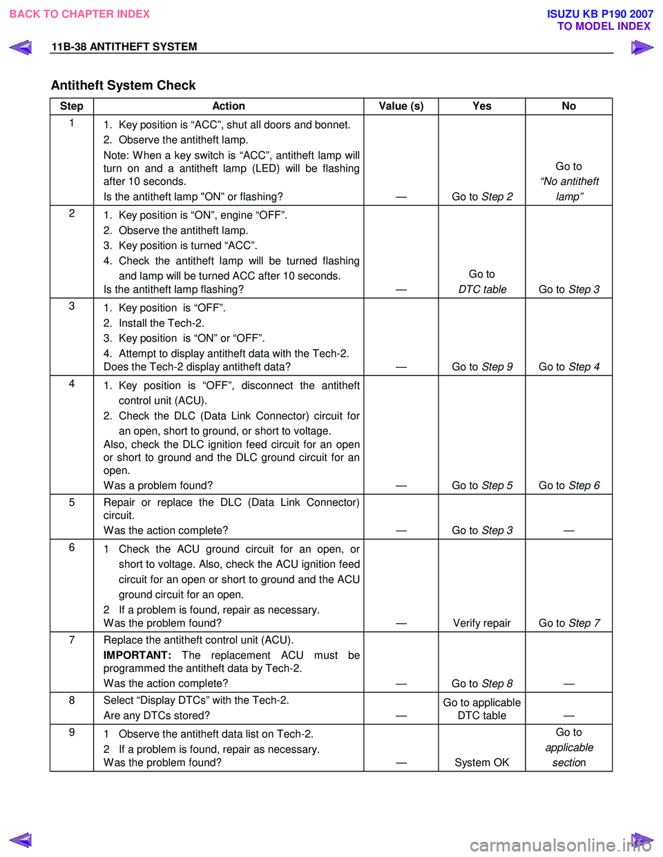
Antitheft System Check
Step Action Value (s) Yes No
1
1. Key position is “ACC”, shut all doors and bonnet.
2. Observe the antitheft lamp.
Note: W hen a key switch is “ACC”, antitheft lamp will
turn on and a antitheft lamp (LED) will be flashing
after 10 seconds.
Is the antitheft lamp "ON” or flashing? — Go to Step 2 Go to
“No antitheft lamp”
2
1. Key position is “ON”, engine “OFF”.
2. Observe the antitheft lamp.
3. Key position is turned “ACC”.
4. Check the antitheft lamp will be turned flashing and lamp will be turned ACC after 10 seconds.
Is the antitheft lamp flashing? — Go to
DTC table Go to Step 3
3
1. Key position is “OFF”.
2. Install the Tech-2.
3. Key position is “ON” or “OFF”.
4. Attempt to display antitheft data with the Tech-2.
Does the Tech-2 display antitheft data? — Go to Step 9 Go to Step 4
4
1. Key position is “OFF”, disconnect the antitheft
control unit (ACU).
2. Check the DLC (Data Link Connector) circuit for an open, short to ground, or short to voltage.
Also, check the DLC ignition feed circuit for an open
or short to ground and the DLC ground circuit for an
open.
W as a problem found? — Go to Step 5 Go to Step 6
5 Repair or replace the DLC (Data Link Connector)
circuit.
W as the action complete? — Go to Step 3 —
6
1 Check the ACU ground circuit for an open, or
short to voltage. Also, check the ACU ignition feed
circuit for an open or short to ground and the ACU
ground circuit for an open.
2 If a problem is found, repair as necessary.
W as the problem found? — Verify repair Go to Step 7
7
Replace the antitheft control unit (ACU).
IMPORTANT: The replacement ACU must be
programmed the antitheft data by Tech-2.
W as the action complete? — Go to Step 8 —
8 Select “Display DTCs” with the Tech-2.
Are any DTCs stored? — Go to applicable
DTC table —
9
1 Observe the antitheft data list on Tech-2.
2 If a problem is found, repair as necessary.
W as the problem found? — System OK Go to
applicable sectio n
BACK TO CHAPTER INDEX
TO MODEL INDEX
ISUZU KB P190 2007
Page 5993 of 6020

ANTITHEFT SYSTEM 11B-39
No Antitheft Lamp
Step Action Value (s) Yes No
1 Check the fuse for the antitheft power feed circuit.
(10A)
If a problem found, repair as necessary.
W as the problem found?
Is the action complete? — Verify repair Go to Step 2
2
1. Check the ACU ground circuit for an open, or
short to voltage. Also, check the ACU ignition feed
circuit for an open or short to ground and the ACU
ground circuit for an open.
2. If a problem is found, repair as necessary.
W as the problem found? — Verify repair Go to Step 3
3
1. Check the antitheft lamp LED circuit for an open,
or short to voltage.
2. If a problem is found, repair as necessary.
W as the problem found? — Verify repair Go to Step 4
4
1. Key position is “OFF”.
2. Install the Tech-2.
3. Key position is “ACC” or “OFF”.
4. Observe to display lamp data with the Tech-2.
Does the Tech-2 display antitheft lamp data ON? — Go to Step 5 Go to Step 6
5 Replace the antitheft lamp. — Verify repair —
6 Replace the antitheft control unit (ACU).
IMPORTANT: The replacement ACU must be
programmed the antitheft data by Tech-2.
W as the action complete? — Verify repair —
BACK TO CHAPTER INDEX
TO MODEL INDEX
ISUZU KB P190 2007