body ISUZU KB P190 2007 Workshop Repair Manual
[x] Cancel search | Manufacturer: ISUZU, Model Year: 2007, Model line: KB P190, Model: ISUZU KB P190 2007Pages: 6020, PDF Size: 70.23 MB
Page 2522 of 6020
Engine Mechanical – V6 Page 6A1–43
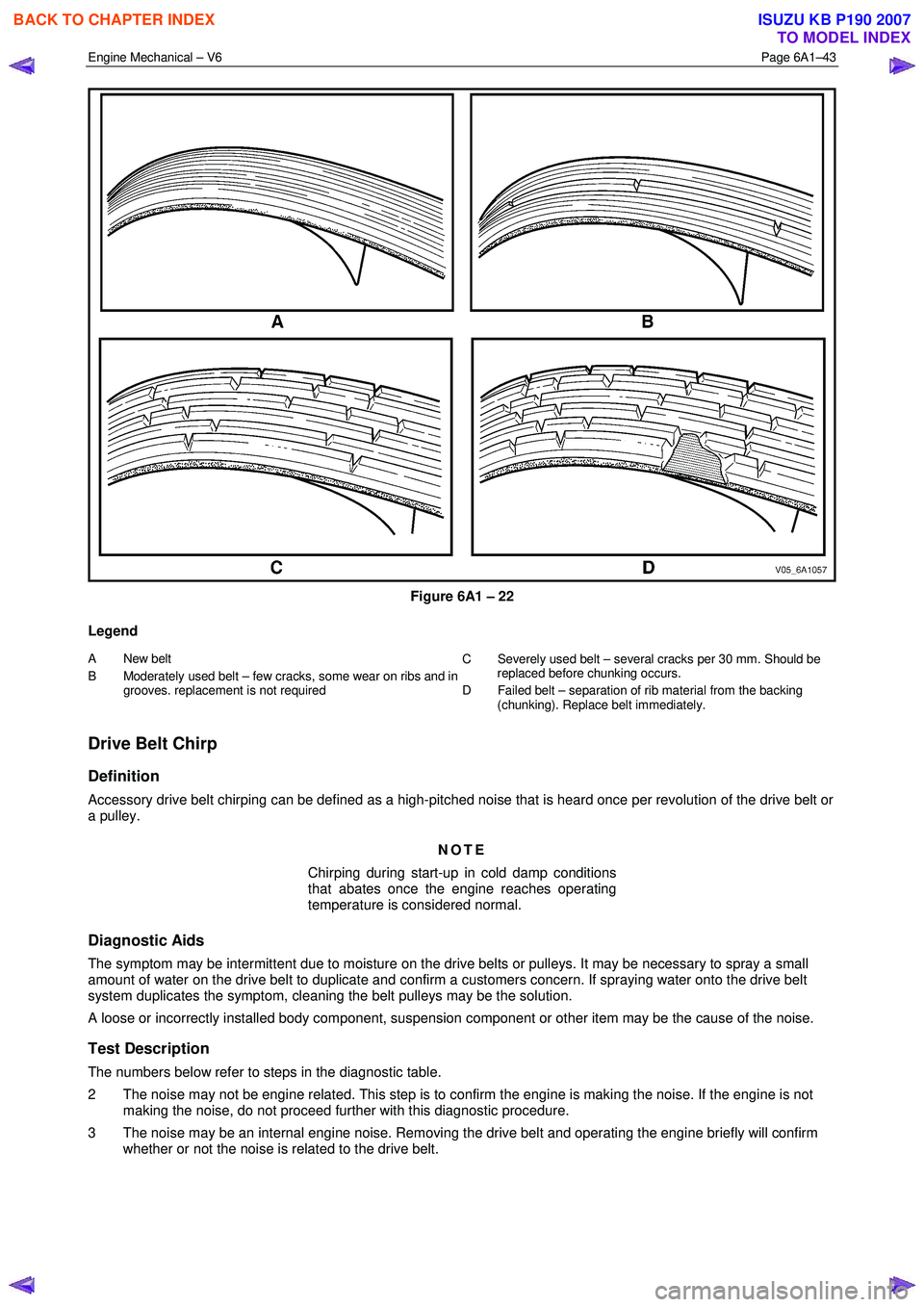
Figure 6A1 – 22
Legend
A New belt
B Moderately used belt – few cra cks, some wear on ribs and in
grooves. replacement is not required C Severely used belt – several cracks per 30 mm. S
hould be
replaced before chunking occurs.
D Failed belt – separation of rib material from the backing (chunking). Replace belt immediately.
Drive Belt Chirp
Definition
Accessory drive belt chirping can be defined as a high-pitched noise that is heard once per revolution of the drive belt or
a pulley.
NOTE
Chirping during start-up in cold damp conditions
that abates once the engine reaches operating
temperature is considered normal.
Diagnostic Aids
The symptom may be intermittent due to moisture on the drive belts or pulleys. It may be necessary to spray a small
amount of water on the drive belt to duplicate and confirm a customers concern. If spraying water onto the drive belt
system duplicates the symptom, cleaning the belt pulleys may be the solution.
A loose or incorrectly installed body component, suspension component or other item may be the cause of the noise.
Test Description
The numbers below refer to steps in the diagnostic table.
2 The noise may not be engine related. This step is to confirm the engine is making the noise. If the engine is not making the noise, do not proceed further with this diagnostic procedure.
3 The noise may be an internal engine noise. Removing the drive belt and operating the engine briefly will confirm whether or not the noise is related to the drive belt.
BACK TO CHAPTER INDEX
TO MODEL INDEX
ISUZU KB P190 2007
Page 2524 of 6020
Engine Mechanical – V6 Page 6A1–45
Step Action Yes No
10 Inspect for missing, loose or incorrect fasteners.
Did you find any missing, loose or incorrect fasteners? Go to Step 11 Go to Step 12
11 Tighten any loose fasteners to the torque specification as provided in
provided in 6. Torque W rench Specifications.
Replace any incorrect or missing fasteners.
Did you complete the repairs? Go to Step 15 —
12 Inspect for a bent pulley. Did you find any bent pulleys? Go to Step 13 Go to Step 14
13 Replace bent pulleys as required. Did you complete the repair? Go to Step 15 —
14 Replace the accessory drive belt, refer to 3.5 Accessory Drive Belt.
Did you complete the repair? Go to Step 15 —
15 Reinstall the accessory drive belt and operate the system to confirm the repair.
Did you correct the chirp noise? Accessory drive
system OK Go to 2.2
Symptoms, and restart the
diagnosis
Drive Belt Squeal
Definition
Accessory drive belt squealing can be defined as a loud screeching noise caused by a slipping drive belt. Belt squeal is
unusual in multi-rib belts. Drive belt squeal generally occurs when a heavy load is applied to the drive belt, such as an
air-conditioning compressor engagement, snapping the throttle, seized pulley or a faulty accessory drive component.
Diagnostic Aids
If the noise is intermittent, confirm the accessory drive components by varying their loads, making sure they are operated
to their maximum capacity. An overcharged A/C system, restrictions in the power steering pressure circuit or a faulty
generator or coolant pump are likely causes of accessory drive belt squeal.
A loose or incorrectly installed body component, suspension component or other item may be the cause of the noise.
Test Description
The numbers below refer to steps in the diagnostic table.
2 The noise may not be engine related. This step is to confirm the engine is making the noise. If the engine is not making the noise, do not proceed further with this diagnostic procedure.
3 The noise may be an internal engine noise. Removing the drive belt and operating the engine briefly will confirm whether or not the noise is related to the drive belt.
CAUTION
When running the engine with the accessory
drive belt removed, the coolant pump will not
be operating and the engine may overheat if
left unsupervised even for a short period.
NOTE
There may also be a number of DTCs set when
running the engine with the accessory drive belt
removed.
4 Confirms an accessory drive component does not have a seized bearing. W ith the belt removed, test the bearings in the accessory drive components spin free and smooth.
5 Confirms the drive belt tensioner is operating correctly. If the drive belt tensioner is not operating correctly, drive belt tension will not be maintained, resulting in a belt squealing noise
6 Confirms the belt is not too long, which would prevent the tensioner from working as intended. Also, if an excessively long belt has been fitted, it may also be routed incorrectly and may be turning an accessory drive
component in the wrong direction.
BACK TO CHAPTER INDEX
TO MODEL INDEX
ISUZU KB P190 2007
Page 2527 of 6020

Engine Mechanical – V6 Page 6A1–48
NOTE
Pilling is the small balls (pills) or strings of rubber
in the belt grooves caused by the accumulation of
rubber dust.
Diagnostic Aids
Vibration from the engine may cause a body component or other parts to emit a rumbling noise.
The drive belt may have a condition that cannot be seen or felt. Sometimes the replacement of the belt may be the only
way to confirm the belt is faulty.
If the drive belt has been replaced and the diagnostic table completed, but the rumble is still present only when the drive
belt is installed, an accessory drive component such as the A/C compressor may be the cause. Varying the load to each
accessory drive component in turn, should help isolate which component is causing the noise.
Test Description
The numbers below refer to steps in the diagnostic table.
2 Confirms the symptom exists at the time of diagnosis. Other vehicle components may be causing the noise.
3 Confirms the accessory drive belt is the cause of the noise. Drive belt rumbling is often confused with an internal engine noise due to the similarity in the description. Removing the drive belt and operating the engine briefly will
confirm whether or not the noise is related to the drive belt.
CAUTION
When running the engine with the accessory
drive belt removed, the coolant pump will not
be operating and the engine may overheat if
left unsupervised even for a short period.
NOTE
There may also be a number of DTCs set when
running the engine with the accessory drive belt
removed.
4 Inspecting the drive belt is to ensure that it is not causing the noise. Small cracks across the ribs of the drive belt will not cause the noise and are not justification alone to replace the belt. Belt separation can be identified by the
ply of the belt separating and may be seen at the edge of the belt or felt as lumps under the belt.
5 Small amounts of pilling is a normal condition and is deemed acceptable. W hen the pilling is severe (33% of the belt groove depth), the belt does not have a smooth surface to run on and should be replaced.
Diagnostic Table
Step Action Yes No
1 Did you review the information provided in 2.2 Symptoms, and
perform the required inspections. Go to Step 2 Go to 2.2
Symptoms
2 Confirm the customer complaint. Is there a rumbling noise? Go to Step 3 Refer to Diagnostic
Aids in this Section
3 1 Remove the drive belt, refer to 3.5 Accessory Drive Belt.
2 Operate the engine for no more than 40 seconds.
Does the rumbling noise still exist? Accessory drive
system OK
Go to 2.2
Symptoms,
and restart the diagnosis Go to Step 4
4 Inspect the accessory drive belt for damage, separation or sections of missing ribs.
Did you find any damaged, separated or missing ribs? Go to Step 7 Go to Step 5
5 Inspect the accessory drive belt for severe pilling (exceeding 33% of the belt groove depth).
Did you find sever pilling? Go to Step 6 Go to Step 5
BACK TO CHAPTER INDEX
TO MODEL INDEX
ISUZU KB P190 2007
Page 2531 of 6020
Engine Mechanical – V6 Page 6A1–52
Diagnostic Aids
Excessive wear of a drive belt is usually caused by an incorrect installation or an incorrect drive belt fitted. Minor pulley
misalignment will not cause excessive wear, but will cause the drive belt to fall off. Major pulley misalignment may cause
excessive wear, but would also result in the drive belt falling off.
Test Description
The numbers below refer to steps in the diagnostic table.
2 Confirms the drive belt is correctly installed onto all of the accessory drive system pulleys. W ear on the drive belt may be caused by incorrectly positioning the drive belt by one or more grooves to a particular pulley.
3 The installation of the drive belt that is the incorrect width will cause wear on the drive belt. The drive belt ribs should match all the grooves on all the pulleys in the accessory drive system.
4 Confirms the drive belt is not contacting any parts of the engine or body while the engine is running. There should be sufficient clearance when the accessory drive component loads varies. The drive belt should not come into
contact with any engine or body parts.
Diagnostic Table
Step Action Yes No
1 Did you review the information provided in 2.2 Symptoms, and
perform the required inspections. Go to Step 2 Go to 2.2
Symptoms
2 Inspect the accessory drive belt for correct installation.
Is the drive belt installed correctly? Go to Step 5 Go to Step 3
3 Ensure that the drive belt is the correct one for the application. Is the correct drive belt installed? Go to Step 5 Go to Step 4
4 Is the drive belt contacting any engine or body components with the engine running? Go to Step 6 Refer to Diagnostic
Aids in this Section
5 Install a new accessory drive belt, refer to 3.5 Accessory Drive Belt.
Did you replace the accessory drive belt? Go to Step 6 —
6 If required, reinstall the accessory drive belt and operate the system to confirm the repair.
Did you correct the excessive wear? Accessory drive
system OK Go to Step 2
Accessory Drive Belt Tensioner Diagnosis
Diagnostic Table
Step Action Yes No
1 1 Remove the accessory drive belt.
2 Inspect the drive belt tensioner pulley.
Is the drive belt tensioner pulley loose or misaligned? Go to Step 4 Go to Step 2
2 Rotate the drive belt tensioner.
Does the drive belt tensioner rotate freely, without any unusual
resistance or binding? Go to Step 3 Go to Step 4
3 1 Using a suitable torque wrench, measure the torque required to
lift the drive belt tensioner off the stop.
2 Using a known good tensioner, measure the torque required to lift the drive belt tensioner off the stop.
Is the first torque reading within 10% of the second reading?
Accessory drive belt tensioner OK Go to Step 4
4 Replace the drive belt tensioner, refer to
3.7 Accessory Drive Belt Tensioner Assembly.
Is the repair complete?
Accessory drive belt tensioner OK —
BACK TO CHAPTER INDEX
TO MODEL INDEX
ISUZU KB P190 2007
Page 2538 of 6020

Engine Mechanical – V6 Page 6A1–59
3.5 Accessory Drive Belt
RWD Vehicle
Remove
1 Remove the air intake duct from between the air flow meter and the throttle body, refer to 6C1-3 Engine
Management – V6 – Service Operations.
2 Note the accessory drive belt (1) routing.
Figure 6A1 – 29
3 Using a suitable ½” drive socket bar (1), rotate the drive belt tensioner (2) clockwise, to reduce belt
tension.
4 W hile holding the tensioner in the reduced tension position, remove the accessory drive belt (3).
NOTE
If required use an assistant to maintain the tensioner in the required position.
CAUTION
If running the engine with the accessory
drive belt removed, the coolant pump will
not be operating and the engine may
overheat if left unsupervised even for a short
period.
Figure 6A1 – 30
Reinstall
1 Install the drive belt over the A/C compressor, idler pulley, power steering pump, coolant pump, generator and tensioner pulleys.
2 Using a suitable ½” drive socket bar (1), rotate the drive belt tensioner (2) clockwise, refer to Figure 6A1 – 30.
3 W ith an assistant holding the tensioner in the required position, feed the accessory drive belt (3) over the crankshaft pulley.
4 Slowly release the drive belt tensioner mechanism.
BACK TO CHAPTER INDEX
TO MODEL INDEX
ISUZU KB P190 2007
Page 2539 of 6020
Engine Mechanical – V6 Page 6A1–60
NOTE
Ensure the drive belt ribs are correctly aligned
with the grooves in the accessory drive pulleys or
damage to the drive belt and accessory drive
components and pulleys may occur.
5 Reinstall the air intake duct to the air flow meter and the throttle body, refer to 6C1-3 Engine Management – V6 – Service Operations.
6 Run the engine to ensure correct operation.
3.6 Accessory Drive Belt Idler Pulley
Remove
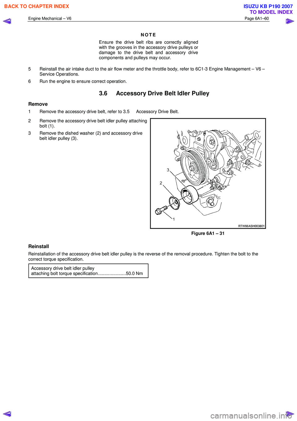
1 Remove the accessory drive belt, refer to 3.5 Accessory Drive Belt.
2 Remove the accessory drive belt idler pulley attaching bolt (1).
3 Remove the dished washer (2) and accessory drive belt idler pulley (3).
Figure 6A1 – 31
Reinstall
Reinstallation of the accessory drive belt idler pulley is the reverse of the removal procedure. Tighten the bolt to the
correct torque specification.
Accessory drive belt idler pulley
attaching bolt torque specification ......................50.0 Nm
BACK TO CHAPTER INDEX
TO MODEL INDEX
ISUZU KB P190 2007
Page 2543 of 6020
Engine Mechanical – V6 Page 6A1–64
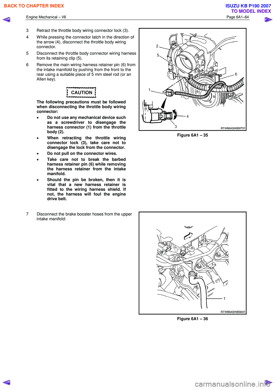
3 Retract the throttle body wiring connector lock (3).
4 W hile pressing the connector latch in the direction of the arrow (4), disconnect the throttle body wiring
connector.
5 Disconnect the throttle body connector wiring harness from its retaining clip (5).
6 Remove the main wiring harness retainer pin (6) from the intake manifold by pushing from the front to the
rear using a suitable piece of 5 mm steel rod (or an
Allen key).
The following precautions must be followed
when disconnecting the throttle body wiring
connector:
• Do not use any mechanical device such
as a screwdriver to disengage the
harness connector (1) from the throttle
body (2).
• When retracting the throttle wiring
connector lock (3), take care not to
disengage the lock from the connector.
• Do not pull on the connector wires.
• Take care not to break the barbed
harness retainer pin (6) while removing
the harness retainer from the intake
manifold.
• Should the pin be broken, then it is
vital that a new harness retainer is
fitted to the wiring harness shield. If
not, the harness will foul the engine
drive belt.
Figure 6A1 – 35
7 Disconnect the brake booster hoses from the upper intake manifold:
Figure 6A1 – 36
BACK TO CHAPTER INDEX
TO MODEL INDEX
ISUZU KB P190 2007
Page 2545 of 6020
Engine Mechanical – V6 Page 6A1–66
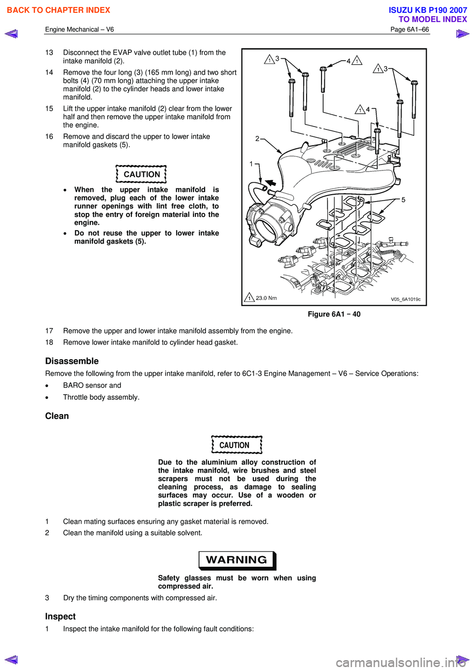
13 Disconnect the EVAP valve outlet tube (1) from the
intake manifold (2).
14 Remove the four long (3) (165 mm long) and two short bolts (4) (70 mm long) attaching the upper intake
manifold (2) to the cylinder heads and lower intake
manifold.
15 Lift the upper intake manifold (2) clear from the lower half and then remove the upper intake manifold from
the engine.
16 Remove and discard the upper to lower intake manifold gaskets (5).
• When the upper intake manifold is
removed, plug each of the lower intake
runner openings with lint free cloth, to
stop the entry of foreign material into the
engine.
• Do not reuse the upper to lower intake
manifold gaskets (5).
Figure 6A1 –
––
–
40
17 Remove the upper and lower intake manifold assembly from the engine.
18 Remove lower intake manifold to cylinder head gasket.
Disassemble
Remove the following from the upper intake manifold, refer to 6C1-3 Engine Management – V6 – Service Operations:
• BARO sensor and
• Throttle body assembly.
Clean
CAUTION
Due to the aluminium alloy construction of
the intake manifold, wire brushes and steel
scrapers must not be used during the
cleaning process, as damage to sealing
surfaces may occur. Use of a wooden or
plastic scraper is preferred.
1 Clean mating surfaces ensuring any gasket material is removed.
2 Clean the manifold using a suitable solvent.
Safety glasses must be worn when using
compressed air.
3 Dry the timing components with compressed air.
Inspect
1 Inspect the intake manifold for the following fault conditions:
BACK TO CHAPTER INDEX
TO MODEL INDEX
ISUZU KB P190 2007
Page 2546 of 6020
Engine Mechanical – V6 Page 6A1–67
• Damaged sealing and mating surfaces.
• Damaged lower intake manifold gasket.
• Damage or excessive debris on the threaded and through holes.
• Cracks or damage to the intake manifold body.
NOTE
If the lower intake manifold is cracked or
damaged, it must be replaced. No welding or
patching of the intake manifold should be
performed.
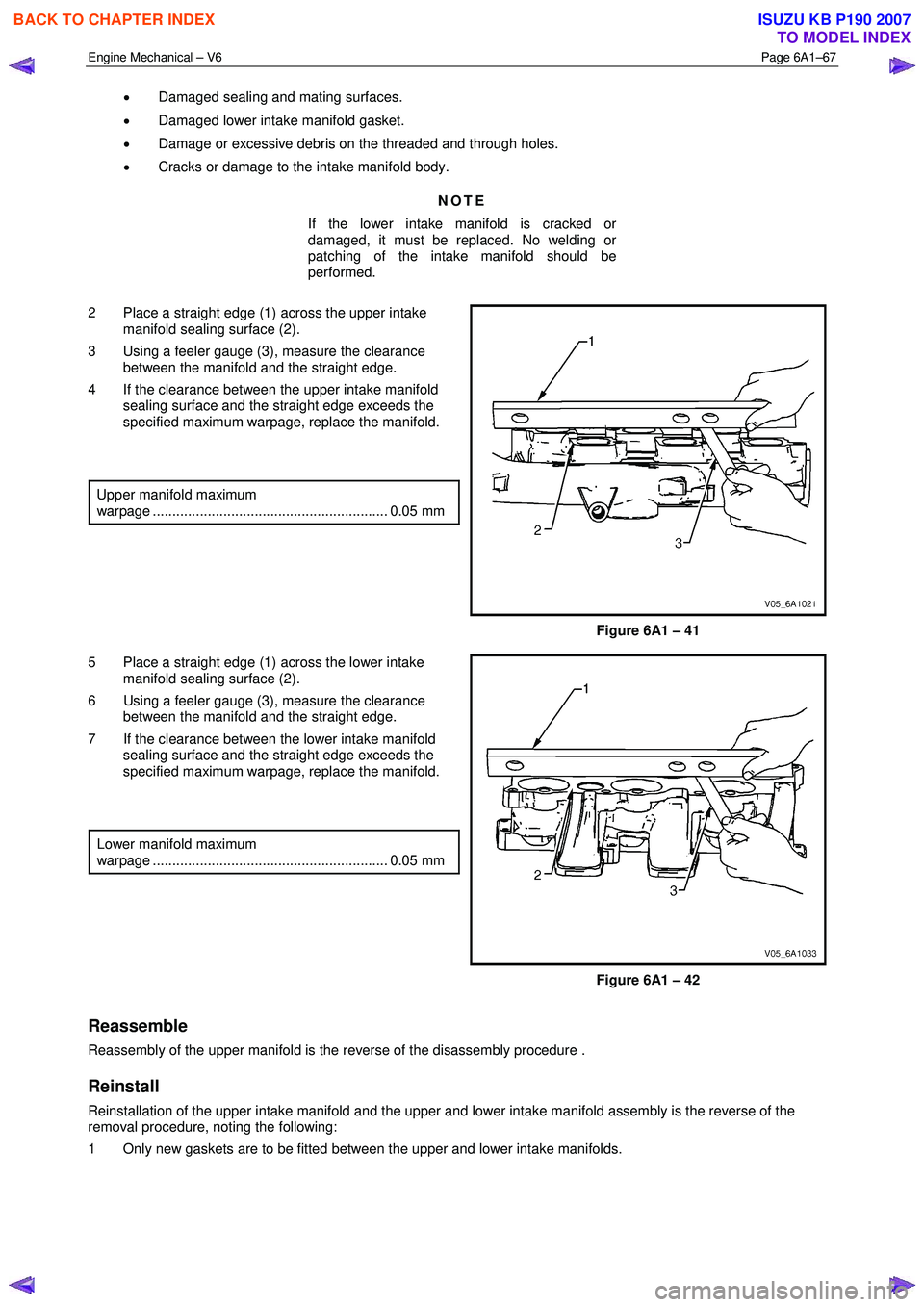
2 Place a straight edge (1) across the upper intake manifold sealing surface (2).
3 Using a feeler gauge (3), measure the clearance between the manifold and the straight edge.
4 If the clearance between the upper intake manifold sealing surface and the straight edge exceeds the
specified maximum warpage, replace the manifold.
Upper manifold maximum
warpage ............................................................ 0.05 mm
Figure 6A1 – 41
5 Place a straight edge (1) across the lower intake manifold sealing surface (2).
6 Using a feeler gauge (3), measure the clearance between the manifold and the straight edge.
7 If the clearance between the lower intake manifold sealing surface and the straight edge exceeds the
specified maximum warpage, replace the manifold.
Lower manifold maximum
warpage ............................................................ 0.05 mm
Figure 6A1 – 42
Reassemble
Reassembly of the upper manifold is the reverse of the disassembly procedure .
Reinstall
Reinstallation of the upper intake manifold and the upper and lower intake manifold assembly is the reverse of the
removal procedure, noting the following:
1 Only new gaskets are to be fitted between the upper and lower intake manifolds.
BACK TO CHAPTER INDEX
TO MODEL INDEX
ISUZU KB P190 2007
Page 2548 of 6020
Engine Mechanical – V6 Page 6A1–69
3 Remove the air intake duct (1) and hose (2), refer to
6C1-3 Engine Management – V6 – Service
Operations.
Figure 6A1 – 43
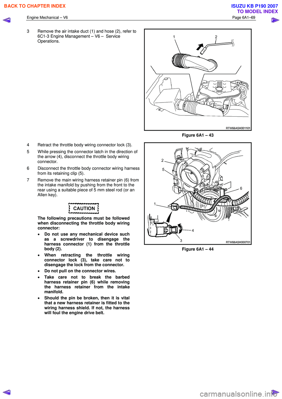
4 Retract the throttle body wiring connector lock (3).
5 W hile pressing the connector latch in the direction of the arrow (4), disconnect the throttle body wiring
connector.
6 Disconnect the throttle body connector wiring harness from its retaining clip (5).
7 Remove the main wiring harness retainer pin (6) from the intake manifold by pushing from the front to the
rear using a suitable piece of 5 mm steel rod (or an
Allen key).
The following precautions must be followed
when disconnecting the throttle body wiring
connector:
• Do not use any mechanical device such
as a screwdriver to disengage the
harness connector (1) from the throttle
body (2).
• When retracting the throttle wiring
connector lock (3), take care not to
disengage the lock from the connector.
• Do not pull on the connector wires.
• Take care not to break the barbed
harness retainer pin (6) while removing
the harness retainer from the intake
manifold.
• Should the pin be broken, then it is vital
that a new harness retainer is fitted to the
wiring harness shield. If not, the harness
will foul the engine drive belt.
Figure 6A1 – 44
BACK TO CHAPTER INDEX
TO MODEL INDEX
ISUZU KB P190 2007