body ISUZU KB P190 2007 Workshop Repair Manual
[x] Cancel search | Manufacturer: ISUZU, Model Year: 2007, Model line: KB P190, Model: ISUZU KB P190 2007Pages: 6020, PDF Size: 70.23 MB
Page 2229 of 6020
ENGINE DRIVEABILITY AND EMISSIONS 6E–59
POSITIVE CRANKCASE VENTILATION
(PCV) SYSTEM
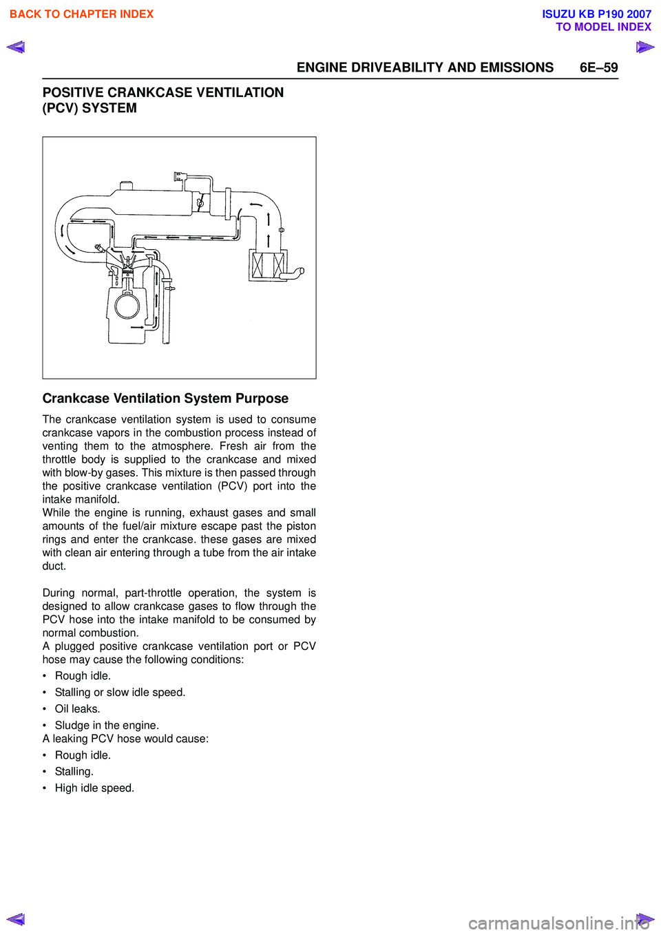
Crankcase Ventilation System Purpose
The crankcase ventilation system is used to consume
crankcase vapors in the combustion process instead of
venting them to the atmosphere. Fresh air from the
throttle body is supplied to the crankcase and mixed
with blow-by gases. This mixture is then passed through
the positive crankcase ventilation (PCV) port into the
intake manifold.
While the engine is running, exhaust gases and small
amounts of the fuel/air mixture escape past the piston
rings and enter the crankcase. these gases are mixed
with clean air entering through a tube from the air intake
duct.
During normal, part-throttle operation, the system is
designed to allow crankcase gases to flow through the
PCV hose into the intake manifold to be consumed by
normal combustion.
A plugged positive crankcase ventilation port or PCV
hose may cause the following conditions:
• Rough idle.
• Stalling or slow idle speed.
• Oil leaks.
• Sludge in the engine.
A leaking PCV hose would cause:
• Rough idle.
• Stalling.
• High idle speed.
BACK TO CHAPTER INDEX
TO MODEL INDEX
ISUZU KB P190 2007
Page 2235 of 6020
ENGINE DRIVEABILITY AND EMISSIONS 6E–65
Step 3: Simulate the symptom and isolate the
problem
Simulate the symptom and isolate the system by
reproducing all possible conditions suggested in Step 1
while monitoring suspected circuits/components/
systems to isolate the problem symptom. Begin with the
most logical circuit/component.
Isolate the circuit by dividing the suspect system into
simpler circuits. Next, confine the problem into a smaller
area of the system. Begin at the most logical point (or
point of easiest access) and thoroughly check the
isolated circuit for the fault, using basic circuit tests.
Hints
You can isolate a circuit by:
• Unplugging connectors or removing a fuse to separate one part of the circuit from another
• If only component fails to operate, begin testing the component
• If a number of components do not operate, begin test at areas of commonality (such as power sources,
ground circuits, switches, main connectors or major
components)
• Substitute a known good part from the parts department or the vehicle system
• Try the suspect part in a known good vehicle
See Symptom Simulation Tests on the next page for
problem simulation procedures. Refer to service manual
sections 6E and 8A for information about intermittent
diagnosis. Follow procedures for basic circuit testing in
service manual section 8A.
What resources you should use
Whenever appropriate, you should use the following
resources to assist in the diagnostic process:
• Service manual
• Bulletins
• Digital multimeter (with a MIN/MAX feature)
• Tech II and Tech II upload function
• Circuit testing tools (including connector kits/ harnesses and jumper wires)
• Experience
• Intermittent problem solving simulation methods
• Customer complaint check sheet
Symptom Simulation Tests
1. Vibration
This method is useful when the customer complaint
analysis indicates that the problem occurs when the
vehicle/system undergoes some form of vibration.
For connectors and wire harness, slightly shake
vertically and horizontally. Inspect the connector joint
and body for damage. Also, tapping lightly along a
suspected circuit may be helpful. For parts and sensors, apply slight vibration to the part
with a light tap of the finger while monitoring the system
for a malfunction.
2. Heat
This method is important when the complaint suggests
that the problem occurs in a heated environment. Apply
moderate heat to the component with a hair drier or
similar tool while monitoring the system for a
malfunction.
CAUTION: Care must be take to avoid overheating
the component.
3. Water and Moisture
This method may be used when the complaint suggests
that the malfunction occurs on a rainy day or under
conditions of high humidity. In this case, apply water in a
light spray on the vehicle to duplicate the problem.
CAUTION: Care must be take to avoid directly
exposing electrical connections to water.
4. Electrical loads
This method involves turning systems ON (such as the
blower, lights or rear window defogger) to create a load
on the vehicle electrical system at the same time you
are monitoring the suspect circuit/component.
5e. Vehicle Operates as Designed
This condition refers to instances where a system
operating as designed is perceived to be unsatisfactory
or undesirable. In general, this is due to:
• A lack of understanding by the customer
• A conflict between customer expectations and vehicle design intent
• A system performance that is unacceptable to the customer
What you should do
You can verify that a system is operating as designed
by:
• Reviewing service manual functional/diagnostic checks
• Examining bulletins and other service information for supplementary information
• Compare system operation to an identical vehicle
If the condition is due to a customer misunderstanding
or a conflict between customer expectation and system
operation, you should explain the system operation to
the customer.
If the complaint is due to a case of unsatisfactory
system performance, you should contact Technical
Assistance for the latest information.
What resources you should use
Whenever possible, you should use the following
resources to facilitate the diagnostic process:
BACK TO CHAPTER INDEX
TO MODEL INDEX
ISUZU KB P190 2007
Page 2240 of 6020

6E–70 ENGINE DRIVEABILITY AND EMISSIONS
Tech 2 Operating Flow Cart (Start Up)
Select “2.XL L4 HV240” in Vehicle Identification menu and the following table is shown in the Tech 2 screen.
System Selection Menu
F0: Powertrain
F1: Chassis
F3: Body
Select “(TF/UC)”.
Vehicle Identification
4JH1-TC Bosch
4JH1-T Denso
2.XL L4 HV240
3.5L V6 6VE1 Hitachi
AW30-40LE
AT JR405E
Select “F0: Powertrain”.
Main Menu
F0: Diagnostic
F1: Service Programming System (SPS)
F2: View Capture Data
F3: Tool Option
F4: Download/ Upload Help
Press “ENTER” key.
Vehicle Identification
(3) 2003
(2) 2002
(1) 2001
(Y) 2000
(X) 1999
(W) 1998
Select “F0: Diagnostic”.
Select “(3) 2003” or later.
Press (ENTER) to Continue
Select “2.XL L4 HV240”.
Vehicle Identification
(UB) Trooper, Bighorn
(UE) Rodeo,/Amigo, Wizard/Mu
(TF/UC) LUV, Frontier, LAO-Rodeo
(TBR)
(N*) ELF, NPR, NQR
BACK TO CHAPTER INDEX
TO MODEL INDEX
ISUZU KB P190 2007
Page 2255 of 6020

ENGINE DRIVEABILITY AND EMISSIONS 6E–85
2. Demand of Data1. Connect Tech-2 to the vehicle. When activated by turning on the power of Tech-2, push the “Enter”
switch.
2. Turn on the ignition switch (without starting the engine)
3. In the main menu of Diagnostic Tester, push “F1: Service Programming System (SPS)”.
4. Push “F0: Request Info” of Tech-2. 5. Where vehicle data has been already saved in Tech
2, the existing data come on display. In this
instance, as Tech-2 starts asking whether to keep
the data or to continue obtaining anew data from the
control unit, choose either of them
6. If you select “continue”, you have to select “Model Year”, “Vehicle Type”.
7. After that. then push button and turn Ignition switch tuned on, off, on following Tech-2 display. Tech-2
will read information from controller after this
procedure.
8. During obtaining information, Tech-2 is receiving information from the control unit ECM and TCM (A/T
only) at the same time. With VIN not being
programmed into the new control unit at the time of
shipment, "obtaining information" is not complete
(because the vehicle model, engine model and
model year are specified from VIN). For the
procedure get additional information on vehicles,
instruction will be provided in dialog form, when
TIS2000 is in operation.
9. Following instructions by Tech-2, push the “Exit” switch of Tech-2, turn off the ignition of the vehicle
and turn off the power of Tech-2, thereby removing
from the vehicle. 3. Data Exchange
1. Connect Tech-2 to P/C, turn on the power and click the “Next” button of P/C.
2. Check VIN of the vehicle and choose “Next”.
3. Select “System Type” for required control unit.
• Engine (Programming for ECM or PCM)
• Transmission (Programming for TCM)
4. When a lack of data is asked from among the following menu, enter accordingly.
Select following Menu
• Model Year
• Model
• Engine type
• Transmission type
• Destination code (vehicles for general export)*1
• Immobilizer
Etc.
* 1: How to read the destination code
Destination code can be read from ID Plate affixed on
vehicles, while on VIN plate the destination code is
described at the right-hand edge of Body Type line. In
the figure, the destination code can be read as "RR3"
(Australia).
BACK TO CHAPTER INDEX
TO MODEL INDEX
ISUZU KB P190 2007
Page 2276 of 6020

6E–106 ENGINE DRIVEABILITY AND EMISSIONS
10 Repair the open circuit between the fuel pump relayand battery.
Is the action complete? — Verify repair —
11 Using the DVM and check the fuel pump power supply circuit.
1. Ignition “On”, engine “Off”.
2. Disconnect the fuel pump connector.
3. Check the circuit for open or short to ground circuit.
Was the DVM indicated specified value?
10 - 14.5V Go to Step 13Go to Step 12
12 Repair the open or short to ground circuit between the fuel pump relay and fuel pump.
Is the action complete? — Verify repair —
13 Using the DVM and check the fuel pump ground circuit.
1. Ignition “Off”, engine “Off”.
2. Disconnect the fuel pump connector.
3. Check the circuit for open circuit.
Was the DVM indicated specified value?
Continuity Go to Step 15Go to Step 14
14 Repair the open circuit between the fuel pump and body ground.
Is the action complete? — Verify repair —
15 Replace the fuel pump. Was the problem solved? — Verify repair Go to Step 16
16 Is the ECM programmed with the latest software release?
If not, download the latest software to the ECM using
the “SPS (Service Programming System)”.
Was the problem solved? — Verify repair Go to Step 17
Step
Action Value(s) Yes No
V
1
F2
F-2
Ω
4
BACK TO CHAPTER INDEX
TO MODEL INDEX
ISUZU KB P190 2007
Page 2322 of 6020

6E–152 ENGINE DRIVEABILITY AND EMISSIONS
• Poor ECM to engine block grounds.
• Fuel pressure - The system will go lean if pressure is too low. The ECM can compensate for some
decrease. However, if fuel pressure is too low, a
Diagnostic Trouble Code P0131 may be set. Refer to
Fuel System Diagnosis.
• Lean injector(s) - Perform “Injector Balance Test.”
• Vacuum leaks - Check for disconnected or damaged vacuum hoses and for vacuum leaks at the intake
manifold, throttle body, EGR system, and PCV
system. • Exhaust leaks - An exhaust leak may cause outside
air to be pulled into the exhaust gas stream past the
HO2S, causing the system to appear lean. Check for
exhaust leaks that may cause a false lean condition
to be indicated.
• Fuel contamination - Water, even in small amounts, can be delivered to the fuel injectors. The water can
cause a lean exhaust to be indicated. Excessive
alcohol in the fuel can also cause this condition. For
the procedure to check for fuel contamination, Refer
to Fuel System Diagnosis.
Diagnostic Trouble Code (DTC) P0131
O
2 Sensor Circuit Low Voltage (Bank 1 Sensor 1)
Step Action Value(s) Yes No
1 Was the “On-Board Diagnostic (OBD) System Check” performed?
—Go to Step 2Go to
On Board
Diagnostic
(OBD) System Check
2 1. Connect the Tech 2. 2. Review and record the failure information.
3. Select “F0: Read DTC Infor By Priority” in “F0: Diagnostic Trouble Code”.
Is the DTC P0131 stored as “Present Failure”? — Go to Step 3Refer to
Diagnostic Aids and Go to Step
3
3 1. Using the Tech2, ignition “On” and engine “Off”. 2. Select “Clear DTC Information” with the Tech2 andclear the DTC information.
3. Operate the vehicle and monitor the “F5: Failed This Ignition” in “F2: DTC Information”.
Was the DTC P0131 stored in this ignition cycle? — Go to Step 4Refer to
Diagnostic Aids and Go to Step
4
4 Check for poor/faulty connection at the O
2 sensor or
ECM connector. If a poor/faulty connection is found,
repair as necessary.
Was the problem found?
— Verify repair Go to Step 5
5 Using the DVM and check the O
2 sensor circuit.
1. Ignition “On”, engine “Off”.
2. Disconnect the O
2 sensor connector.
3. Check the circuit for short to heater ground or ground circuit.
Was the DVM indicated specified value?
Approximatly 450mV Go to Step 7Go to Step 6
C56(J2) E77
31 216
V
21
E77
BACK TO CHAPTER INDEX
TO MODEL INDEX
ISUZU KB P190 2007
Page 2324 of 6020

6E–154 ENGINE DRIVEABILITY AND EMISSIONS
9 1. Using the Tech 2, ignition “On” and engine “On”. 2. Monitor the “Manifold Absolute Pressure” in thedata display.
Does the Tech 2 indicate correct “Manifold Absolute
Pressure” in accordance with engine speed or
acceleration? — Go to Step 11Go to Step 10
10 Remove the MAP sensor and check for the following conditions.
• Objects blocking the air cleaner.
• Objects blocking the MAP sensor.
• Objects blocking the throttle valve.
• Vacuum leaking at intake duct.
• Vacuum leaking at throttle body.
If a problem is found, repair as necessary.
Was the problem found? — Verify repair Go to Step 11
11 1. Using the Tech 2, ignition “On” and engine “On”. 2. Select the “Miscellaneous Test” and perform the“IAC Control” in the “IAC System”.
3. Operate the Tech 2 in accordance with procedure.
Was the engine speed changed, when the IAC valve
is operating step by step? — Go to Step 13Go to Step 12
12 Check for the following conditions. • Objects blocking the IAC valve.
• Objects blocking the throttle valve.
• Vacuum leaking at throttle body.
If a problem is found, repair as necessary.
Was the problem found? — Verify repair Go to Step 13
13 Check for injector for the affected bank. Refer to “Injector Coil Test & Injector Balance Test
Procedure” 6E-98 page .
Was the injector operation correct? —Go to Step 14Refer to
Injector
Coil Test & Injector
Balance Test Procedure
14 Check for fuel pressure. Refer to “Fuel System Diagnosis” 6E-108 page.
Was the fuel pressure correct? — Go to Step 15Refer to
Fuel
System
Diagnosis
15 Replace the O
2 sensor.
Was the problem solved? — Verify repair Go to Step 16
16 Is the ECM programmed with the latest software release?
If not, download the latest software to the ECM using
the “SPS (Service Programming System)”.
Was the problem solved? — Verify repair Go to Step 17
17 Replace the ECM. Is the action complete?
IMPORTANT: The replacement ECM must be
programmed. Refer to section of the Service
Programming System (SPS) in this manual.
Following ECM programming, the immobilizer system
(if equipped) must be linked to the ECM. Refer to
section 11 “Immobilizer System-ECM replacement” for
the ECM/Immobilizer linking procedure. — Verify repair —
Step
Action Value(s) Yes No
BACK TO CHAPTER INDEX
TO MODEL INDEX
ISUZU KB P190 2007
Page 2327 of 6020
ENGINE DRIVEABILITY AND EMISSIONS 6E–157
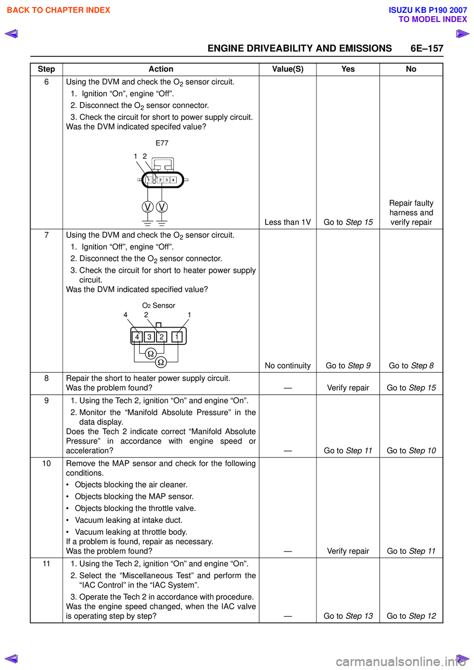
6 Using the DVM and check the O2 sensor circuit.
1. Ignition “On”, engine “Off”.
2. Disconnect the O
2 sensor connector.
3. Check the circuit for short to power supply circuit.
Was the DVM indicated specifed value?
Less than 1V Go to Step 15Repair faulty
harness and verify repair
7 Using the DVM and check the O
2 sensor circuit.
1. Ignition “Off”, engine “Off”.
2. Disconnect the the O
2 sensor connector.
3. Check the circuit for short to heater power supply circuit.
Was the DVM indicated specified value?
No continuity Go to Step 9Go to Step 8
8 Repair the short to heater power supply circuit. Was the problem found? — Verify repair Go to Step 15
9 1. Using the Tech 2, ignition “On” and engine “On”. 2. Monitor the “Manifold Absolute Pressure” in thedata display.
Does the Tech 2 indicate correct “Manifold Absolute
Pressure” in accordance with engine speed or
acceleration? — Go to Step 11Go to Step 10
10 Remove the MAP sensor and check for the following conditions.
• Objects blocking the air cleaner.
• Objects blocking the MAP sensor.
• Objects blocking the throttle valve.
• Vacuum leaking at intake duct.
• Vacuum leaking at throttle body.
If a problem is found, repair as necessary.
Was the problem found? — Verify repair Go to Step 11
11 1. Using the Tech 2, ignition “On” and engine “On”. 2. Select the “Miscellaneous Test” and perform the“IAC Control” in the “IAC System”.
3. Operate the Tech 2 in accordance with procedure.
Was the engine speed changed, when the IAC valve
is operating step by step? — Go to Step 13Go to Step 12
Step
Action Value(S) Yes No
12
VV
E77
1
24
1234
O2 Sensor
BACK TO CHAPTER INDEX
TO MODEL INDEX
ISUZU KB P190 2007
Page 2328 of 6020
6E–158 ENGINE DRIVEABILITY AND EMISSIONS
12 Check for the following conditions. • Objects blocking the IAC valve.
• Objects blocking the throttle valve.
• Vacuum leaking at throttle body.
If a problem is found, repair as necessary.
Was the problem found? — Verify repair Go to Step 13
13 Check for injector for the affected bank. Refer to “Injector Coil Test & Injector Balance Test
Procedure” 6E-98 page .
Was the injector operation correct? —Go to Step 14Refer to
Injector
Coil Test & Injector
Balance Test Procedure
14 Check for fuel pressure. Refer to “Fuel System Diagnosis” 6E-108 page .
Was the fuel pressure correct? — Go to Step 15Refer to
Fuel
System
Diagnosis
15 Replace the O
2 sensor.
Was the problem solved? — Verify repair Go to Step 16
16 Is the ECM programmed with the latest software release?
If not, download the latest software to the ECM using
the “SPS (Service Programming System)”.
Was the problem solved? — Verify repair Go to Step 17
17 Replace the ECM. Is the action complete?
IMPORTANT: The replacement ECM must be
programmed. Refer to section of the Service
Programming System (SPS) in this manual.
Following ECM programming, the immobilizer system
(if equipped) must be linked to the ECM. Refer to
section 11 “Immobilizer System-ECM replacement” for
the ECM/Immobilizer linking procedure. — Verify repair —
Step
Action Value(S) Yes No
BACK TO CHAPTER INDEX
TO MODEL INDEX
ISUZU KB P190 2007
Page 2331 of 6020
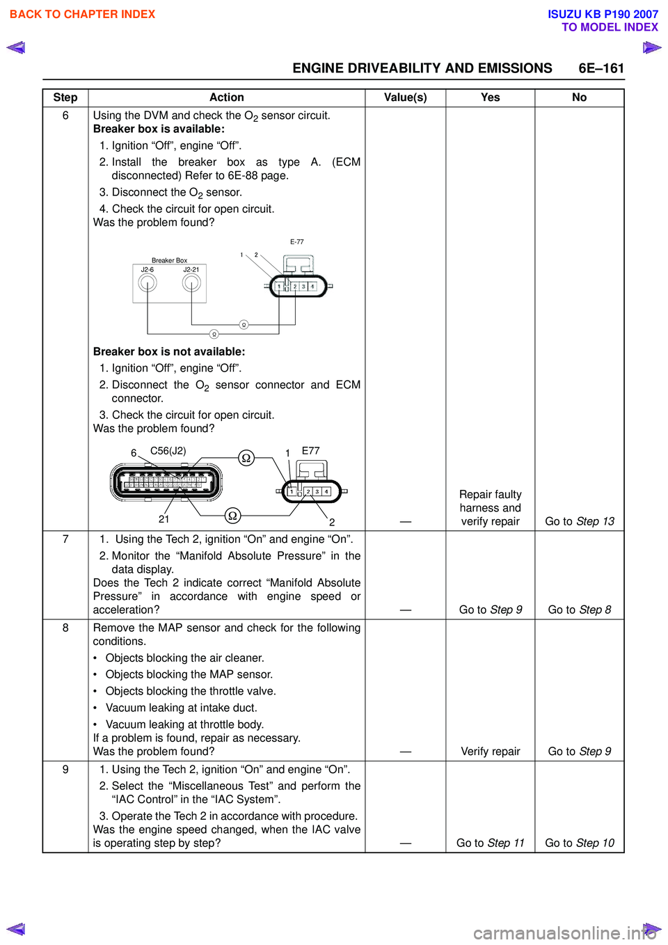
ENGINE DRIVEABILITY AND EMISSIONS 6E–161
6 Using the DVM and check the O2 sensor circuit.
Breaker box is available:
1. Ignition “Off”, engine “Off”.
2. Install the breaker box as type A. (ECM disconnected) Refer to 6E-88 page.
3. Disconnect the O
2 sensor.
4. Check the circuit for open circuit.
Was the problem found?
Breaker box is not available: 1. Ignition “Off”, engine “Off”.
2. Disconnect the O
2 sensor connector and ECM
connector.
3. Check the circuit for open circuit.
Was the problem found?
—Repair faulty
harness and verify repair Go to Step 13
7 1. Using the Tech 2, ignition “On” and engine “On”. 2. Monitor the “Manifold Absolute Pressure” in thedata display.
Does the Tech 2 indicate correct “Manifold Absolute
Pressure” in accordance with engine speed or
acceleration? — Go to Step 9Go to Step 8
8 Remove the MAP sensor and check for the following conditions.
• Objects blocking the air cleaner.
• Objects blocking the MAP sensor.
• Objects blocking the throttle valve.
• Vacuum leaking at intake duct.
• Vacuum leaking at throttle body.
If a problem is found, repair as necessary.
Was the problem found? — Verify repair Go to Step 9
9 1. Using the Tech 2, ignition “On” and engine “On”. 2. Select the “Miscellaneous Test” and perform the“IAC Control” in the “IAC System”.
3. Operate the Tech 2 in accordance with procedure.
Was the engine speed changed, when the IAC valve
is operating step by step? — Go to Step 11Go to Step 10
Step
Action Value(s) Yes No
J2-6J2-21
Breaker Box
E-77
21
ΩΩ
1
2
21
6C56(J2) E77
BACK TO CHAPTER INDEX
TO MODEL INDEX
ISUZU KB P190 2007