brake sensor ISUZU KB P190 2007 Workshop Repair Manual
[x] Cancel search | Manufacturer: ISUZU, Model Year: 2007, Model line: KB P190, Model: ISUZU KB P190 2007Pages: 6020, PDF Size: 70.23 MB
Page 4064 of 6020

7A2-98 TRANSMISSION CONTROL SYSTEM (AW30–40LE)
Condition For Setting The DTC
The TCM detects following conditions for 0.5 seconds
continuously at shifting.
• Voltage at connector pin is 0V when solenoid is “ON”.
(DTC P0976)
• Voltage at connector pin is ignition voltage when
solenoid is “OFF”. (DTC P0977)
Action Taken When The DTC Sets
• No L-up control.
• No line pressure reduction control at gear change.
• No torque reduction control.
• No squat control.
• No slope control (keep mode).
• No line pressure reduction control at garage.
• No input revolution sensor failure detection.
• No shift solenoid failure detection.
• No L-up solenoid failure detection.
• Change to emergency mode.
• Check Trans “ON”.
• DTC stored.
• MIL request “ON”. (EURO 4 only)
Conditions For Clearing The DTC
•
The DTC can be cleared from the TCM history by
using a scan tool.
• The DTC will be cleared from history when the vehicle has achieved 40 warm-up cycles without a
failure reported.
•
After more than 1 second has elapsed after the
ignition key has been turned “ON”, short between
No.11 and No.4 (ground) of DLC (Data Link
Connector). Then, after 1 second, but within 6
seconds, discontinue shorting.
Diagnostic Aids
• Inspect the wiring for poor electrical connection at the
TCM. Look for possible bent, backed out, deformed
or damaged terminals. Check for weak terminal
tension as well. Also check for a chafed wire that
could short to bare metal or other wiring.
Inspect for a broken wire inside the insulation.
• W hen diagnosing for a possible intermittent short o
r
open condition, move the wiring harness while
observing test equipment for a change.
Circuit/System Testing DTC P0976 or P0977
Step Action Value(s) YES NO
1
W as the On-Board Diagnostic (OBD) System Check
performed? — Go to
Step 2 Go to OBD
System Check
2 1. Install a scan tool.
2. Start the engine.
3. Depress the brake pedal and place the select lever in D position.
4. Press the 3rd start switch. (Turn the 3rd start switch “ON”.)
5. Press the 3rd start switch again. (Turn the 3rd start switch “OFF”.)
Does a scan tool indicate DTC P0976 or P0977? — Go to
Step 3 Refer to
Diagnostic Aids
3 1. Turn “ON” the ignition with the engine “ON”.
2. Place the selector lever in the “P” position.
3. Measure the voltage between terminal C94-15 and terminal C94-1 on the TCM pigtail connector by 5-
8840-0285-0 DMM.
Is the voltage specified value? 8∼16V Go to
Step 4 Go to Step 5
BACK TO CHAPTER INDEX
TO MODEL INDEX
ISUZU KB P190 2007
Page 4086 of 6020
ON-VEHICLE SERVICE (AW30–40LE) 7A3-1
SECTION 7A3
ON-VEHICLE SERVICE (AW30–40LE)
TABLE OF CONTENTS
Service Precaution .................................................. 7A3-2
Diagnosis ................................................................. 7A3-3
Basic Troubleshooting ........................................ 7A3-3
Manual Shifting Test ........................................... 7A3-9
Stall Test ............................................................... 7A3-9
Time Lag Test ...................................................... 7A3-10
Hydraulic Test ...................................................... 7A3-11
Road Test ............................................................. 7A3-12
Shift Point Chart and Lock-Up Point Chart ..........7A3-16
Shift Point Chart ................................................... 7A3-16
Lock-Up Point Chart ............................................ 7A3-17
Transmission Fluid Level and Condition ..............7A3-18
Inspection ............................................................. 7A3-18
ATF Replacement ................................................... 7A3-19
Inspection ............................................................. 7A3-19
Neutral Start Switch (Mode Switch) ......................7A3-20
Inspection ............................................................. 7A3-20
Removal ................................................................ 7A3-20
Installation ............................................................. 7A3-20
Brake Signal ............................................................ 7A3-21
Inspection ............................................................. 7A3-21
Input and Output Revolution Sensor ....................7A3-22
Inspection ............................................................. 7A3-22
Power and 3rd Start switch ....................................7A3-22
Inspection ............................................................. 7A3-22
Solenoid .................................................................... 7A3-23
Inspection ............................................................. 7A3-23
ATF Temperature Sensor ......................................7A3-24
Inspection ............................................................. 7A3-24
Select Lever ....................................................... 7A3-25 Remove or Disconnect .......................................7A3-26
Install or Connect ................................................ 7A3-26
Shift Cable .......................................................... 7A3-28 Remove or Disconnect .......................................7A3-28
Install or Connect ................................................ 7A3-29
Torque Specifications ......................................... 7A3-30
Transmission Control Module (TCM) ...................7A3-31
Removal ............................................................... 7A3-31
Installation ............................................................ 7A3-31
Shift Solenoid and Lock-Up Solenoid ..................7A3-32
Removal ............................................................... 7A3-32
Installation ............................................................ 7A3-33
Valve Body Assembly and Pressure Control Solenoid ................................................. 7A3-34
Removal ............................................................... 7A3-34
Installation ............................................................ 7A3-36
Rear Oil Seal (Adapter Housing, 4 ×4) ................. 7A3-37
Removal ............................................................... 7A3-37
Installation ............................................................ 7A3-37
Rear Oil Seal (Extension Housing, 4 ×2) .............. 7A3-38
Removal ............................................................... 7A3-38
Installation ............................................................ 7A3-38
Transmission Assembly .........................................7A3-39
Transmission and Associated Parts .................7A3-39
Removal ............................................................... 7A3-40
Installation ............................................................ 7A3-44
Major Components .............................................. 7A3-49
BACK TO CHAPTER INDEX
TO MODEL INDEX
ISUZU KB P190 2007
Page 4144 of 6020
UNIT REPAIR (AW30–40LE) 7A4–9
8. Remove the accumulator piston (B–2).
9. Remove the accumulator piston (C –2).
Remove accumulator pistons and springs from
transmission case.
240RY00010
10. Applying compressed air to the oil hole, remove the B–0 accumulator piston and spring.
240RY00011
11. Remove the C –0 accumulator piston.
240RY00012
12. Remove the second brake drum gasket.
13. Remove the solenoid wiring.
Turn over transmission, remove the solenoid
wiring stopper plate from the case.
Pull the wiring out of the transmission case.
14. Remove the snap ring, rotor and key (4 ×4).
Remove the snap ring from the output shaft.
Remove the rotor and key.
247R200002
15. Remove the snap ring, speedometer sensor drive
gear and ball (4 ×2).
Remove the snap ring from the output shaft.
Remove the speedometer sensor drive gear, and
ball.
BACK TO CHAPTER INDEX
TO MODEL INDEX
ISUZU KB P190 2007
Page 4240 of 6020
CONSTRUCTION AND FUNCTION 7A1-1
SECTION 7A1
CONSTRUCTION AND FUNCTION (JR405E)
TABLE OF CONTENTS
PAGE
Description ................................................................................................................... ...7A1- 3
Construction ...............................................................................................................7A1 - 3
Main Data and Specification .....................................................................................7A1- 4
Number Plate Location ..............................................................................................7A1- 5
Electronic Control Components Location ...............................................................7A1- 6
Transmission Control Module (TCM) Peripheral Circuit .........................................7A1- 7
Structure and Function of Component .........................................................................7A1- 8
Torque Converter (with Lock-up Function) .............................................................7A1- 8
Oil Pump .....................................................................................................................7 A1- 9
Input Shaft ..................................................................................................................7 A1- 10
Output Shaft ...............................................................................................................7A1 - 10
Gear Shifting Mechanism ..........................................................................................7A1- 10
Control Valve ..............................................................................................................7A1 - 14
Oil Passage .................................................................................................................7A 1- 19
Parking Function ........................................................................................................7A1- 2 0
Inhibitor Switch ..........................................................................................................7A1- 21
Turbine Sensor ...........................................................................................................7A1- 22
Speed Sensor .............................................................................................................7A1- 22
Accelerator Pedal Position Sensor ..........................................................................7A1- 23
Engine Speed Sensor (=CKP Sensor) ......................................................................7A1- 23
Brake Switch ..............................................................................................................7A1- 24
Mode Select Switch ...................................................................................................7A1- 24
Transmission Control Module (TCM) .......................................................................7A1- 25
Control Mechanism ........................................................................................................7A1- 26
Content of Function and Control ..............................................................................7A1- 26
Control Item, Input and Output .................................................................................7A1- 29
Line Pressure Control ................................................................................................7A1- 30
Lock-up Control .........................................................................................................7A1- 3 0
Direct Electric Shift Control (DESC) .........................................................................7A1- 31
BACK TO CHAPTER INDEX
TO MODEL INDEX
ISUZU KB P190 2007
Page 4242 of 6020
CONSTRUCTION AND FUNCTION 7A1-3
DESCRIPTION
CONSTRUCTION
1 Converter Housing 6 Low Clutch 11 Oil Pump
2 Torque Converter 7 Low & Reverse Brake 12 Control Valve
3 High Clutch 8 Output Shaft 13 Low One-way Clutch
4 Reverse Clutch 9 Extension Housing 14 Parking Gear
5 2-4 Brake 10 Input Shaft
Figure 1. Construction of Automatic Transmission
The JR405E automatic transmission is electrically controlled by a microcomputer transmission control module
(TCM). There are four forward speeds and one reverse speed.
This JR405E automatic transmission employs a clutch pressure direct control system (Direct Electronic Shift
Control: DESC) using duty cycle type solenoids, which ensure high shift quality.
This transmission also has a learning function and constantly checks the time of each clutch and brake
required for the shift in order to match this time with the target value for the optimum shift.
The TCM will automatically select the most appropriate shift points and lock-up points depending on the
Accelerator pedal opening, the vehicle speed and the vehicle load.
If any trouble arises in the speed sensor, APP sensor, solenoid, etc., the fail-safe control function is activated
to keep the running performance.
Problems with the sensors or the solenoids can quickly be detected with the self diagnosis procedure
described in this manual.
The JR405E automatic transmission consists of the torque converter, oil pump, input shaft, out put shaft,
planetary gears and control valves.
The gear train consists of two planetary gear sets and three multiple plate clutches in combination with two
multiple plate brakes and a one-way clutch.
2WD
4WD
BACK TO CHAPTER INDEX
TO MODEL INDEX
ISUZU KB P190 2007
Page 4245 of 6020
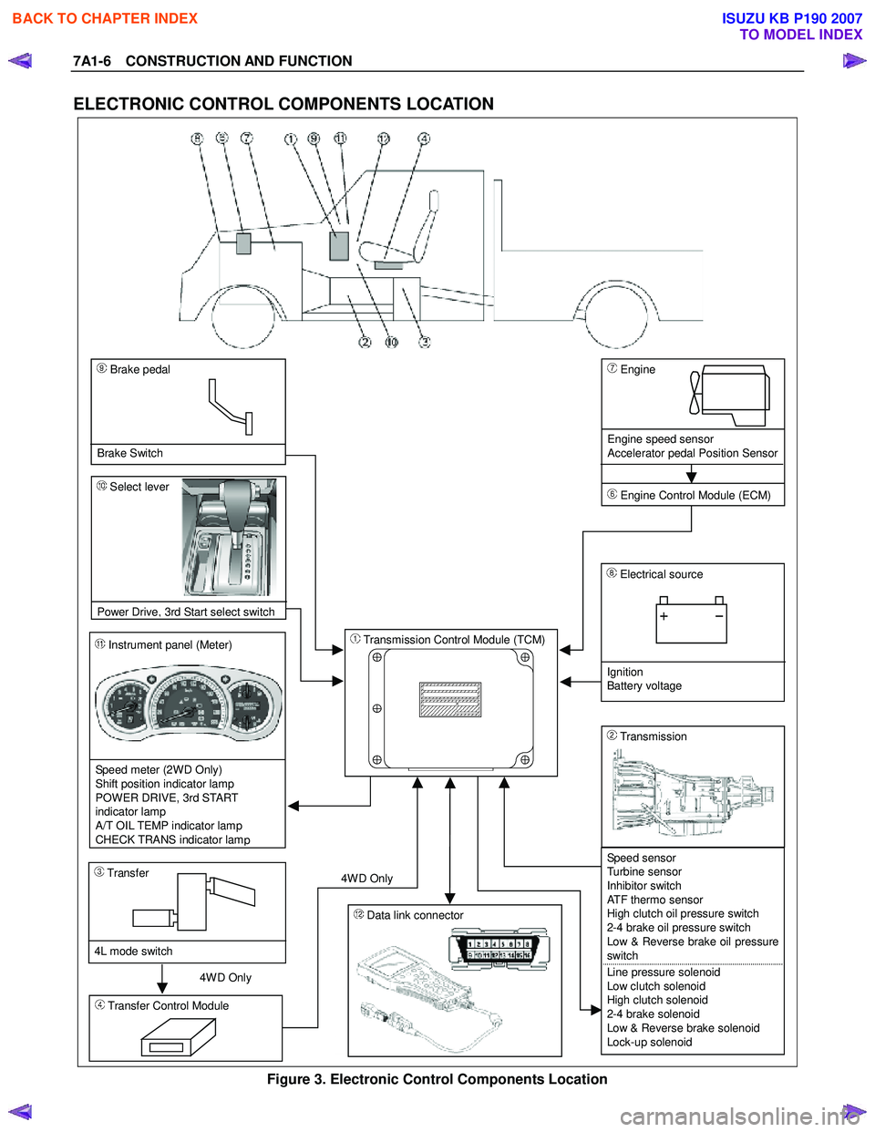
7A1-6 CONSTRUCTION AND FUNCTION
ELECTRONIC CONTROL COMPONENTS LOCATION
4WD Only 4W D Only
Instrument panel (Meter)
Speed meter (2WD Only)
Shift position indicator lamp
POWER DRIVE, 3rd START
indicator lamp
A/T OIL TEMP indicator lamp
CHECK TRANS indicator lam
p
Brake pedal
Brake Switch
Transmission Control Module (TCM)
Electrical source
Ignition
Battery voltage
Speed sensor
Turbine sensor
Inhibitor switch
ATF thermo sensor
High clutch oil pressure switch
2-4 brake oil pressure switch
Low & Reverse brake oil pressure
switch
Line pressure solenoid
Low clutch solenoid
High clutch solenoid
2-4 brake solenoid
Low & Reverse brake solenoid
Lock-up solenoid
Transmission
Transfer Control Module
Transfer
4L mode switch
Engine
Engine speed sensor
Accelerator pedal Position Sensor
Engine Control Module (ECM)
Data link connector
Select lever
Power Drive
, 3rd Start select switch
Figure 3. Electronic Control Components Location
BACK TO CHAPTER INDEX
TO MODEL INDEX
ISUZU KB P190 2007
Page 4257 of 6020

7A1-18 CONSTRUCTION AND FUNCTION
Terminal Assembly Pin No. Connected to Connected TCMPin No.
6 Line Pressure Solenoid B23
12 Low & Reverse Brake Oil Pressure Switch B12
5 Low & Reverse Brake Duty Solenoid B6
11 Ground Return B22
4 Lock-up Duty Solenoid B17
10 High Clutch Duty Solenoid B8
3 Low Clutch Duty Solenoid B9
9 2-4 Brake Duty Solenoid B7
2 Oil Thermo Sensor B4
8 Oil Thermo Sensor Ground B14
1 High Clutch Oil Pressure Switch B20
7 2-4 Brake Oil Pressure Switch B1
123456
891011127
Terminal AssemblyInhibitor Switch
Figure 31. Pin Assignment Figure 32. Location of Terminal Assembly
BACK TO CHAPTER INDEX
TO MODEL INDEX
ISUZU KB P190 2007
Page 4264 of 6020

CONSTRUCTION AND FUNCTION 7A1-25
TRANSMISSION CONTROL MODULE (TCM)
• The TCM is fitted on the side of the brake pedal via two stud bolts.
• The TCM judges the line pressure, gear shifting point and lock-up operation based on electrical signals
from switches and sensors, and sends the appropriate signals to solenoids.
B9 B8 B7 B6 B5 B4 B3 B2 B1 A9 A8 A7 A6 A5 A4 A3 A2 A1
B18 B17 B16 B15 B14 B13 B12 B11 B10 A18 A17 A16 A15 A14 A13 A12 A11 A10
B24 B23 B22 B21 B20 B19 A24 A23 A22 A21 A20 A19
Connect to White Connector Connect to Grey Connector
Figure 49. Pin Assignment
Pin No. Pin Assignment Pin No.Pin Assignment
B1 2-4 Brake Oil Pressure Switch A1 V BATT (Battery Back-up Power Supply)
B2 2 Position Switch A2 P Position Switch
B3 Turbine Sensor A3 Brake Switch
B4 ATF Thermo Sensor A4 3rd Start Indicator Lamp
B5 Ground A5 K-Line Signal (Tech 2 Serial Communication)
B6 Low & Reverse Brake Duty Solenoid A6 No Connection
B7 2-4 Brake Duty Solenoid A7 Engine Speed Sensor
B8 High Clutch Duty Solenoid A8 No Connection
B9 Low Clutch Duty Solenoid A9 No Connection
B10 N Position Switch A10 Vehicle Speed Sensor Out (2W D Only)
B11 D Position Switch A11 3rd START Select Switch
B12 Low & Reverse Brake Oil Pressure Switch A12 4L Mode Switch (4W D Only)
B13 Vehicle Speed Sensor A13 No Connection
B14 ATF Thermo Sensor Ground A14 No Connection
B15 No Connection A15 No Connection
B16 No Connection A16 Accelerator Pedal Position Sensor
B17 Lock-up Duty Solenoid A17 3 Position Switch
B18 Vign (Ignition Power Supply) A18 DIAG Switch (Test Switch)
B19 R Position Switch A19 A/T OIL TEMP Indicator Lamp
B20 High Clutch Oil Pressure Switch A20 CHECK TRANS Indicator Lamp
B21 L Position Switch A21 POW ER DRIVE Indicator Lamp
B22 Ground (Shift Solenoid) A22 No Connection
B23 Line Pressure Solenoid A23 No Connection
B24 Vign (Ignition Power Supply) A24 POW ER DRIVE Select Switch
BACK TO CHAPTER INDEX
TO MODEL INDEX
ISUZU KB P190 2007
Page 4268 of 6020

CONSTRUCTION AND FUNCTION 7A1-29
CONTROL ITEM, INPUT AND OUTPUT
Control item
Item
Line
pressure control
Gear shift
control
Shift
pattern
selection
Lock-up control Direct
electronic shift
control
(DECS)
Learning control
Fail-safe function
Self-
diagnosis function
Speed sensor
Turbine sensor
Engine speed sensor
Brake switch
Inhibitor switch
Mode select switch
4L switch (4W D Only)
ATF thermo sensor
High clutch oil pressure switch
2-4 brake oil pressure switch
Low & Reverse brake oil pressure
switch
Input
Accelerator Pedal position sensor
Line pressure solenoid
Low clutch solenoid
High clutch solenoid
2-4 brake solenoid
Low & Reverse brake solenoid
Lock-up solenoid
Shift pattern indicator lamp
ATF temperature indicator lamp
Output
Check trans indicator lamp
BACK TO CHAPTER INDEX
TO MODEL INDEX
ISUZU KB P190 2007
Page 4270 of 6020

CONSTRUCTION AND FUNCTION 7A1-31
As a result, the lock-up piston is fitted slowly to the converter cover under pressure securing smooth lock-
up engagement.
Figure 51. Lock-up Control
DIRECT ELECTRIC SHIFT CONTROL (DESC)
Feature
• Based on each switch signal (low & reverse brake pressure, 2-4 brake pressure & high clutch pressure)
and each sensor signal (turbine sensor, speed sensor, engine speed signal & APP position signal), the
duty cycle type solenoid adjusts the clutch pressure to match the engine load and vehicle travel
conditions. Controlling the engagement and disengagement of the clutch and brake pressure is directly
and accurately controlled via TCM, which is different to the previous accumulator type.
Operation
• Instead of the previous system (on/off type of shift solenoid and shift valve), the combination of the duty
cycle type solenoid and the amplifier (Amp) valve are used to adjust the clutch pressure to match the
engine load and vehicle travel conditions, based on the signal from the TCM. Also, the pressure switch
provided in the oil passage of the control valve transmits the oil pressure condition (at that time) to TCM,
enabling the engagement and disengagement control of the clutch and brake to be directly and finely
carried out.
• When the gear is shifted from the 2nd to 3rd, 3rd to 4th (O/D), 4th (O/D) to 3rd and 3rd to 2nd, the clutch
pressures on the engagement side and disengagement side are simultaneously controlled.
As a result, engine racing or clutch drag is prevented which enables a smooth and quick shift response.
BACK TO CHAPTER INDEX
TO MODEL INDEX
ISUZU KB P190 2007