Circuit ISUZU KB P190 2007 Workshop Repair Manual
[x] Cancel search | Manufacturer: ISUZU, Model Year: 2007, Model line: KB P190, Model: ISUZU KB P190 2007Pages: 6020, PDF Size: 70.23 MB
Page 1589 of 6020

ENGINE ELECTRICAL (4JK1/4JJ1) 6D-1
SECTION 6D
ENGINE ELECTRICAL
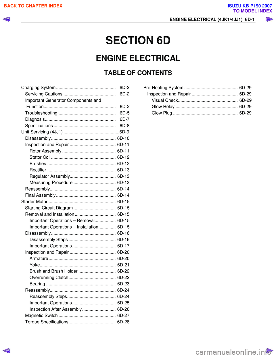
TABLE OF CONTENTS
Charging System ................................................ 6D-2
Servicing Cautions .......................................... 6D-2
Important Generator Components and
Function.......................................................... 6D-2
Troubleshooting .............................................. 6D-5
Diagnosis......................................................... 6D-7
Specifications .................................................. 6D-8
Unit Se rv ic ing (4 JJ 1) ....................................... .... ..6D -9
Disassembly .................................................... 6D-10
Inspection and Repair ..................................... 6D-11 Rotor Assembly ........................................... 6D-11
Stator Coil .................................................... 6D-12
Brushes ....................................................... 6D-12
Rectifier ....................................................... 6D-13
Regulator Assembly..................................... 6D-13
Measuring Procedure .................................. 6D-13
Reassembly..................................................... 6D-14
Final Assembly ................................................ 6D-14
Starter Motor ...................................................... 6D-15 Starting Circuit Diagram .................................. 6D-15
Removal and Installation ................................. 6D-15 Important Operations – Removal................. 6D-15
Important Operations – Installation.............. 6D-15
Disassembly .................................................... 6D-16 Disassembly Steps ...................................... 6D-16
Important Operations ................................... 6D-17
Inspection and Repair ..................................... 6D-20 Armature ...................................................... 6D-20
Yoke............................................................. 6D-21
Brush and Brush Holder .............................. 6D-22
Overrunning Clutch...................................... 6D-22
Bearing ........................................................ 6D-23
Reassembly..................................................... 6D-24 Reassembly Steps ....................................... 6D-24
Important Operations ................................... 6D-25
Inspection After Assembly ........................... 6D-26
Magnetic Switch .............................................. 6D-27
Torque Specifications...................................... 6D-28
Pre-Heating System ........................................... 6D-29 Inspection and Repair ..................................... 6D-29 Visual Check................................................ 6D-29
Glow Relay .................................................. 6D-29
Glow Plug .................................................... 6D-29
BACK TO CHAPTER INDEX
TO MODEL INDEX
ISUZU KB P190 2007
Page 1590 of 6020

6D-2 ENGINE ELECTRICAL (4JK1/4JJ1)
Charging System
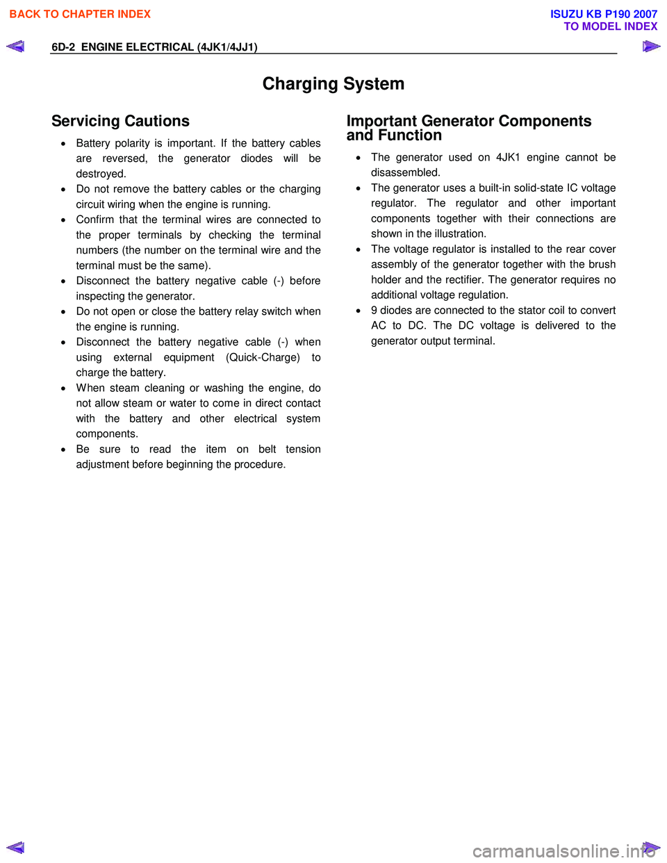
Servicing Cautions
• Battery polarity is important. If the battery cables
are reversed, the generator diodes will be
destroyed.
• Do not remove the battery cables or the charging
circuit wiring when the engine is running.
• Confirm that the terminal wires are connected to
the proper terminals by checking the terminal
numbers (the number on the terminal wire and the
terminal must be the same).
• Disconnect the battery negative cable (-) before
inspecting the generator.
• Do not open or close the battery relay switch when
the engine is running.
• Disconnect the battery negative cable (-) when
using external equipment (Quick-Charge) to
charge the battery.
• W hen steam cleaning or washing the engine, do
not allow steam or water to come in direct contact
with the battery and other electrical system
components.
• Be sure to read the item on belt tension
adjustment before beginning the procedure.
Important Generator Components
and Function
• The generator used on 4JK1 engine cannot be
disassembled.
• The generator uses a built-in solid-state IC voltage
regulator. The regulator and other important
components together with their connections are
shown in the illustration.
• The voltage regulator is installed to the rear cove
r
assembly of the generator together with the brush
holder and the rectifier. The generator requires no
additional voltage regulation.
• 9 diodes are connected to the stator coil to convert
AC to DC. The DC voltage is delivered to the
generator output terminal.
BACK TO CHAPTER INDEX
TO MODEL INDEX
ISUZU KB P190 2007
Page 1599 of 6020

ENGINE ELECTRICAL (4JK1/4JJ1) 6D-11
13.Remove the stator.
066RS030
14.Remove the bolts securing the regulator, the
rectifier, and the brush holder. Separate the parts.
066RW 025
Inspection and Repair
Repair or replace any parts found to be excessively
worn or damaged during the inspection procedure.
Rotor Assembly
1. Check for dirty or rough slip ring surfaces. Remove
dirt from the surfaces with a clean rag. Use No.
500 or No. 600 sandpaper to smooth the surfaces.
2. Measure the slip ring diameters. Replace the slip ring if the diameter is less than the specified limit.
Slip ring diameter mm (in)
Standard 27 (1.063)
Limit 26 (1.024)
066RS032
3. Measure the electrical resistance between the slip
rings. If the resistance is greater than the specified
limit (open circuit), repair is required.
Slip ring resistance Ω
Less than 3.75
066RS033
BACK TO CHAPTER INDEX
TO MODEL INDEX
ISUZU KB P190 2007
Page 1603 of 6020

ENGINE ELECTRICAL (4JK1/4JJ1) 6D-15
Starter Motor
Starting Circuit Diagram
RTW 46DSH005501
Removal and Installation
Read this Section carefully before performing any
removal and installation procedure. This Section gives
you important points as well as the order of operation.
Be sure that you understand everything in this Section
before you begin.
Important Operations - Removal
Starter Motor
1. Disconnect the battery cable and the ground cable at the battery terminals.
2. Remove the A/T oil level gage.
3. Remove the Engine oil level gage.
4. Disconnect the magnetic switch cable at the terminal bolts.
5. Disconnect the battery cable at the starter moto
r
and the ground cable at the cylinder body.
6. Remove the starter motor from the engine.
Important Operations – Installation
Follow the removal procedure in the reverse order to
perform the installation procedure. Pay careful attention
to the important points during the installation procedure.
Starter Motor
1. Install the starter motor to the rear plate.
2. Tighten the starter motor bolts to the specified torque.
Starter Motor Bolt Torque N⋅m (kg ⋅m/lb ft)
85 (8.7 / 63)
3. Install the Engine oil level gage.
4. Install the A/T oil level gage.
5. Reconnect the battery cable at the starter moto
r
and the ground cable at the cylinder body.
6. Reconnect the battery cable and the ground cable at the battery terminals.
BACK TO CHAPTER INDEX
TO MODEL INDEX
ISUZU KB P190 2007
Page 1609 of 6020

ENGINE ELECTRICAL (4JK1/4JJ1) 6D-21
5. Use a circuit tester to check the armature for
grounding.
1) Hold one probe of the circuit tester against the commutator segment.
2) Hold the other circuit tester probe against the armature core.
If the circuit tester indicates continuity, the armature is grounded.
The armature must be replaced.
RTW 46DSH003601
6. Use the circuit tester to check the armature for
continuity.
1) Hold the circuit tester probes against two commutator segments.
2) Repair Step 1 at different segments of the armature core.
There should be continuity between all segments of the commutator.
If there is not, the armature must be replaced.
RTW 46DSH003701
Yoke
1. Use a circuit tester to check the field winding
ground.
1) Hold one circuit tester probe against the field winding end or brush.
2) Hold the other circuit tester probe against the bare surface of the yoke body.
There should be no continuity. If there is continuity, the field coil is grounded. The yoke
must be replaced.
RTW 46DSH003801
2. Use the circuit tester to check the field winding
continuity.
1) Hold one circuit tester probe against the “M” terminal lead wire.
2) Hold the other circuit tester probe against the field winding brush.
There should be continuity.If there is no continuity, the yoke must be replaced.
BACK TO CHAPTER INDEX
TO MODEL INDEX
ISUZU KB P190 2007
Page 1610 of 6020

6D-22 ENGINE ELECTRICAL (4JK1/4JJ1)
RTW 46DSH003901
Brush and Brush Holder
1. Use a vernier caliper to measure the brush length
(four brushes).
Replace the brushes as a set if one or more of the brush lengths is less than the specified limit.
Brush Length mm (in)
Standard Limit
15 (0.59) 12 (0.47)
RTW 46DSH004001
2. Use a circuit tester to check the brush holder
insulation.
Touch one probe to the holder plate and the othe
r
probe to the positive brush holder.
There should be no continuity.
RTW 46DSH004101
3. Inspect the brushes for excessive wear.
If the negative brushes have excessive wear, the entire brush holder assembly must be replaced.
If the positive brushes have excessive wear, the entire yoke must be replaced.
Overrunning Clutch
1. Inspect the overrunning clutch gear teeth for
excessive wear and damage.
Replace the overrunning clutch if necessary.
2. Rotate the pinion clockwise.
It should turn smoothly.
3. Try to rotate the pinion in the opposite direction.
The pinion should lock.
065RY00035
BACK TO CHAPTER INDEX
TO MODEL INDEX
ISUZU KB P190 2007
Page 1617 of 6020

ENGINE ELECTRICAL (4JK1/4JJ1) 6D-29
Pre-Heating System
Inspection and Repair
Make the necessary adjustments, repairs, and part
replacement if excessive wear of damage is discovered
during inspection.
Visual Check
Check the main fuses and glow indicator for damage.
Replace the part(s) if required.
Glow Relay
The glow relay is located in the relay box the engine
compartment.
Use an ohmmeter to measure the resistance between
terminals No.2 and No.3.
If the measured value is outside the specified range, the
glow relay must be replaced.
Glow Relay Resistance Ohms
94 - 114
825R300046
Glow Plug
Use a circuit tester to test the glow plugs for continuity.
Glow Plug Resistance (Reference) Ohms
Approximately 0.9
LNW 21KSH001401
BACK TO CHAPTER INDEX
TO MODEL INDEX
ISUZU KB P190 2007
Page 1621 of 6020

6E-4 ENGINE CONTROL SYSTEM (4JK1/4JJ1)
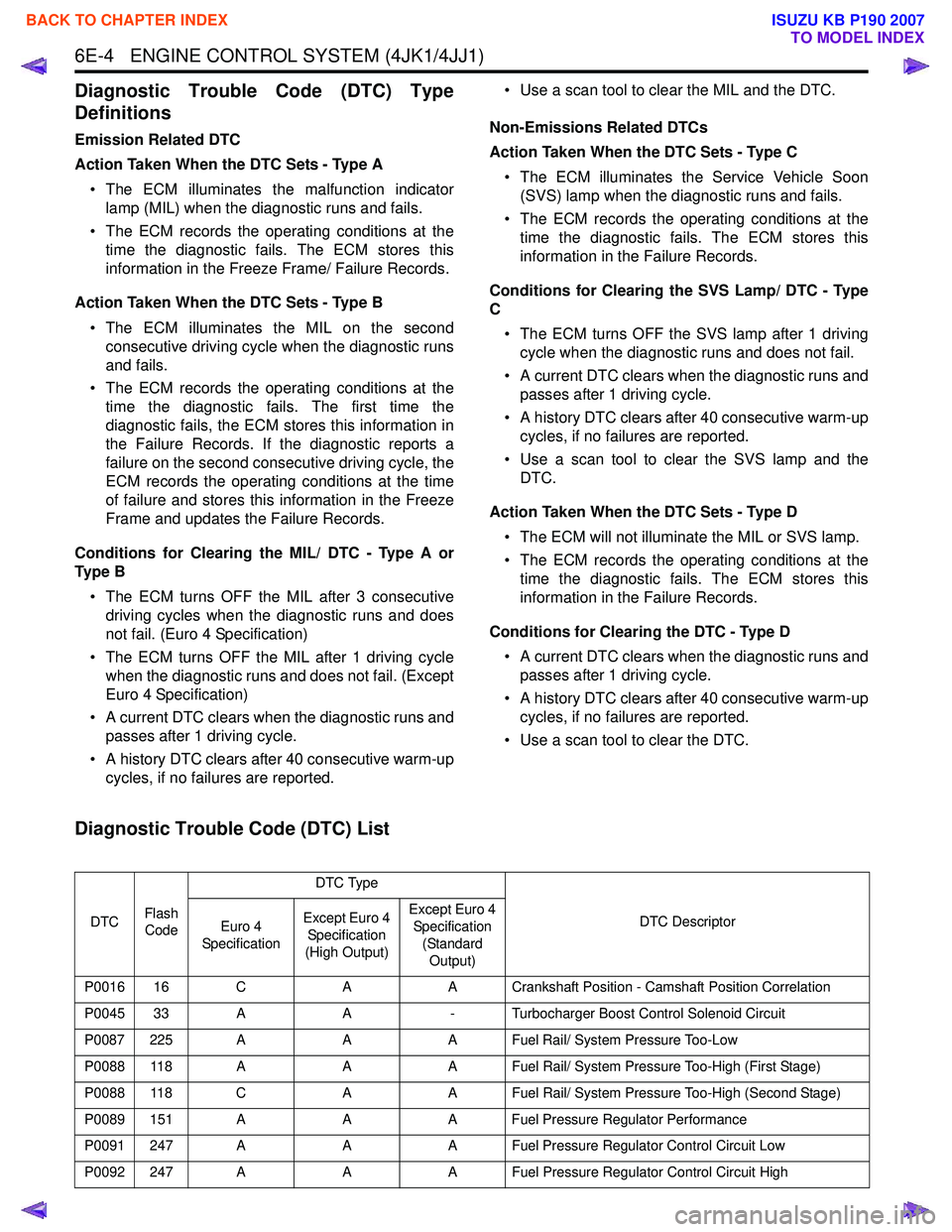
Diagnostic Trouble Code (DTC) Type
Definitions
Emission Related DTC
Action Taken When the DTC Sets - Type A • The ECM illuminates the malfunction indicator lamp (MIL) when the diagnostic runs and fails.
• The ECM records the operating conditions at the time the diagnostic fails. The ECM stores this
information in the Freeze Frame/ Failure Records.
Action Taken When the DTC Sets - Type B • The ECM illuminates the MIL on the second consecutive driving cycle when the diagnostic runs
and fails.
• The ECM records the operating conditions at the time the diagnostic fails. The first time the
diagnostic fails, the ECM stores this information in
the Failure Records. If the diagnostic reports a
failure on the second consecutive driving cycle, the
ECM records the operating conditions at the time
of failure and stores this information in the Freeze
Frame and updates the Failure Records.
Conditions for Clearing the MIL/ DTC - Type A or
Ty p e B
• The ECM turns OFF the MIL after 3 consecutive driving cycles when the diagnostic runs and does
not fail. (Euro 4 Specification)
• The ECM turns OFF the MIL after 1 driving cycle when the diagnostic runs and does not fail. (Except
Euro 4 Specification)
• A current DTC clears when the diagnostic runs and passes after 1 driving cycle.
• A history DTC clears after 40 consecutive warm-up cycles, if no failures are reported. • Use a scan tool to clear the MIL and the DTC.
Non-Emissions Related DTCs
Action Taken When the DTC Sets - Type C
• The ECM illuminates the Service Vehicle Soon (SVS) lamp when the diagnostic runs and fails.
• The ECM records the operating conditions at the time the diagnostic fails. The ECM stores this
information in the Failure Records.
Conditions for Clearing the SVS Lamp/ DTC - Type
C
• The ECM turns OFF the SVS lamp after 1 driving cycle when the diagnostic runs and does not fail.
• A current DTC clears when the diagnostic runs and passes after 1 driving cycle.
• A history DTC clears after 40 consecutive warm-up cycles, if no failures are reported.
• Use a scan tool to clear the SVS lamp and the DTC.
Action Taken When the DTC Sets - Type D • The ECM will not illuminate the MIL or SVS lamp.
• The ECM records the operating conditions at the time the diagnostic fails. The ECM stores this
information in the Failure Records.
Conditions for Clearing the DTC - Type D • A current DTC clears when the diagnostic runs and passes after 1 driving cycle.
• A history DTC clears after 40 consecutive warm-up cycles, if no failures are reported.
• Use a scan tool to clear the DTC.
Diagnostic Trouble Code (DTC) List
DTC Flash
Code DTC Type
DTC Descriptor
Euro 4
Specification Except Euro 4
Specification
(High Output) Except Euro 4
Specification
(Standard Output)
P0016 16 C AA Crankshaft Position - Camshaft Position Correlation
P0045 33 A A- Turbocharger Boost Control Solenoid Circuit
P0087 225 A AA Fuel Rail/ System Pressure Too-Low
P0088 118 A AA Fuel Rail/ System Pressure Too-High (First Stage)
P0088 118 C AA Fuel Rail/ System Pressure Too-High (Second Stage)
P0089 151 A AA Fuel Pressure Regulator Performance
P0091 247 A AA Fuel Pressure Regulator Control Circuit Low
P0092 247 A AA Fuel Pressure Regulator Control Circuit High
BACK TO CHAPTER INDEX
TO MODEL INDEX
ISUZU KB P190 2007
Page 1622 of 6020

ENGINE CONTROL SYSTEM (4JK1/4JJ1) 6E-5
P0093 227 AAA Fuel System Leak Detected
P0101 92 A -- Mass Air Flow Sensor Circuit Range/ Performance
P0102 91 A AA Mass Air Flow Sensor Circuit Low Input
P0103 91 A AA Mass Air Flow Sensor Circuit High Input
P0107 32 A A- Manifold Absolute Pressure Sensor Circuit Low Input
P0108 32 A A- Manifold Absolute Pressure Sensor Circuit High Input
P0112 22 A AA Intake Air Temperature Sensor Circuit Low
P0113 22 A AA Intake Air Temperature Sensor Circuit High
P0116 23 A --Engine Coolant Temperature Sensor Circuit Range/
Performance
P0117 23 A AA Engine Coolant Temperature Sensor Circuit Low
P0118 23 A AA Engine Coolant Temperature Sensor Circuit High
P0122 43 B AA Throttle Position Sensor Circuit Low
P0123 43 B AA Throttle Position Sensor Circuit High
P0182 211 A AA Fuel Temperature Sensor Circuit Low
P0183 211 A AA Fuel Temperature Sensor Circuit High
P0192 245 A AA Fuel Rail Pressure Sensor Circuit Low
P0193 245 A AA Fuel Rail Pressure Sensor Circuit High
P0201 271 A AA Injector Circuit Open - Cylinder 1
P0202 272 A AA Injector Circuit Open - Cylinder 2
P0203 273 A AA Injector Circuit Open - Cylinder 3
P0204 274 A AA Injector Circuit Open - Cylinder 4
P0217 542 D DD Engine Coolant Over Temperature Condition
P0219 543 C AA Engine Overspeed Condition
P0231 69 C AA Fuel Pump Secondary Circuit Low
P0232 69 C AA Fuel Pump Secondary Circuit High
P0234 42 A A- Turbocharger Overboost Condition
P0299 65 A A- Turbocharger Underboost
P0335 15 A AA Crankshaft Position Sensor Circuit
P0336 15 A AA Crankshaft Position Sensor Circuit Range/ Performance
P0340 14 C AA Camshaft Position Sensor Circuit
P0341 14 C AA Camshaft Position Sensor Circuit Range/ Performance
P0380 66 C AA Glow Plug Circuit
P0401 93 A -- EGR Flow Insufficient Detected
P0403 37 B AA EGR Control Circuit
P0404 45 A AA EGR Control Circuit Range/ Performance
P0405 44 B AA EGR Sensor Circuit Low
P0406 44 B AA EGR Sensor Circuit High
P0500 25 A AA Vehicle Speed Sensor
DTC
Flash
Code DTC Type
DTC Descriptor
Euro 4
Specification Except Euro 4
Specification
(High Output) Except Euro 4
Specification (Standard Output)
BACK TO CHAPTER INDEX
TO MODEL INDEX
ISUZU KB P190 2007
Page 1623 of 6020

6E-6 ENGINE CONTROL SYSTEM (4JK1/4JJ1)
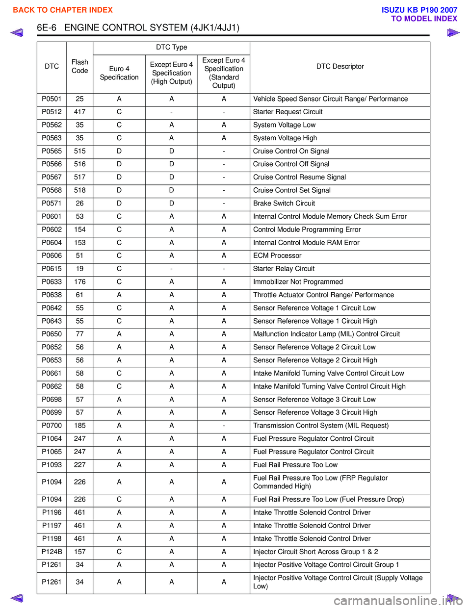
P0501 25 AAA Vehicle Speed Sensor Circuit Range/ Performance
P0512 417 C -- Starter Request Circuit
P0562 35 C AA System Voltage Low
P0563 35 C AA System Voltage High
P0565 515 D D- Cruise Control On Signal
P0566 516 D D- Cruise Control Off Signal
P0567 517 D D- Cruise Control Resume Signal
P0568 518 D D- Cruise Control Set Signal
P0571 26 D D- Brake Switch Circuit
P0601 53 C AA Internal Control Module Memory Check Sum Error
P0602 154 C AA Control Module Programming Error
P0604 153 C AA Internal Control Module RAM Error
P0606 51 C AA ECM Processor
P0615 19 C -- Starter Relay Circuit
P0633 176 C AA Immobilizer Not Programmed
P0638 61 A AA Throttle Actuator Control Range/ Performance
P0642 55 C AA Sensor Reference Voltage 1 Circuit Low
P0643 55 C AA Sensor Reference Voltage 1 Circuit High
P0650 77 A AA Malfunction Indicator Lamp (MIL) Control Circuit
P0652 56 A AA Sensor Reference Voltage 2 Circuit Low
P0653 56 A AA Sensor Reference Voltage 2 Circuit High
P0661 58 C AA Intake Manifold Turning Valve Control Circuit Low
P0662 58 C AA Intake Manifold Turning Valve Control Circuit High
P0698 57 A AA Sensor Reference Voltage 3 Circuit Low
P0699 57 A AA Sensor Reference Voltage 3 Circuit High
P0700 185 A A- Transmission Control System (MIL Request)
P1064 247 A AA Fuel Pressure Regulator Control Circuit
P1065 247 A AA Fuel Pressure Regulator Control Circuit
P1093 227 A AA Fuel Rail Pressure Too Low
P1094 226 A AAFuel Rail Pressure Too Low (FRP Regulator
Commanded High)
P1094 226 C AA Fuel Rail Pressure Too Low (Fuel Pressure Drop)
P1196 461 A AA Intake Throttle Solenoid Control Driver
P1197 461 A AA Intake Throttle Solenoid Control Driver
P1198 461 A AA Intake Throttle Solenoid Control Driver
P124B 157 C AA Injector Circuit Short Across Group 1 & 2
P1261 34 A AA Injector Positive Voltage Control Circuit Group 1
P1261 34 A AAInjector Positive Voltage Control Circuit (Supply Voltage
Low)
DTC
Flash
Code DTC Type
DTC Descriptor
Euro 4
Specification Except Euro 4
Specification
(High Output) Except Euro 4
Specification (Standard Output)
BACK TO CHAPTER INDEX
TO MODEL INDEX
ISUZU KB P190 2007