fuel fill door release ISUZU KB P190 2007 Workshop Repair Manual
[x] Cancel search | Manufacturer: ISUZU, Model Year: 2007, Model line: KB P190, Model: ISUZU KB P190 2007Pages: 6020, PDF Size: 70.23 MB
Page 221 of 6020

2B-24 SHEET METAL
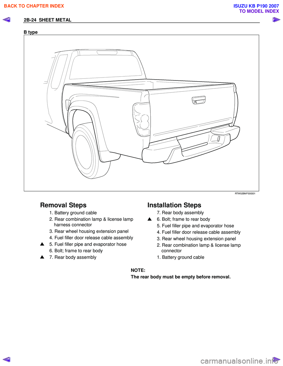
B type
RTW 52BMF000301
Removal Steps Installation Steps
1. Battery ground cable
2. Rear combination lamp & license lamp
harness connector
3. Rear wheel housing extension panel
4. Fuel filler door release cable assembly
5. Fuel filler pipe and evaporator hose
6. Bolt; frame to rear body
7. Rear body assembly
7. Rear body assembly
6. Bolt; frame to rear body
5. Fuel filler pipe and evaporator hose
4. Fuel filler door release cable assembly
3. Rear wheel housing extension panel
2. Rear combination lamp & license lamp
connector
1. Battery ground cable
NOTE:
The rear body must be empty before removal.
BACK TO CHAPTER INDEX
TO MODEL INDEX
ISUZU KB P190 2007
Page 3222 of 6020

Fuel System – V6 Page 6C – 20
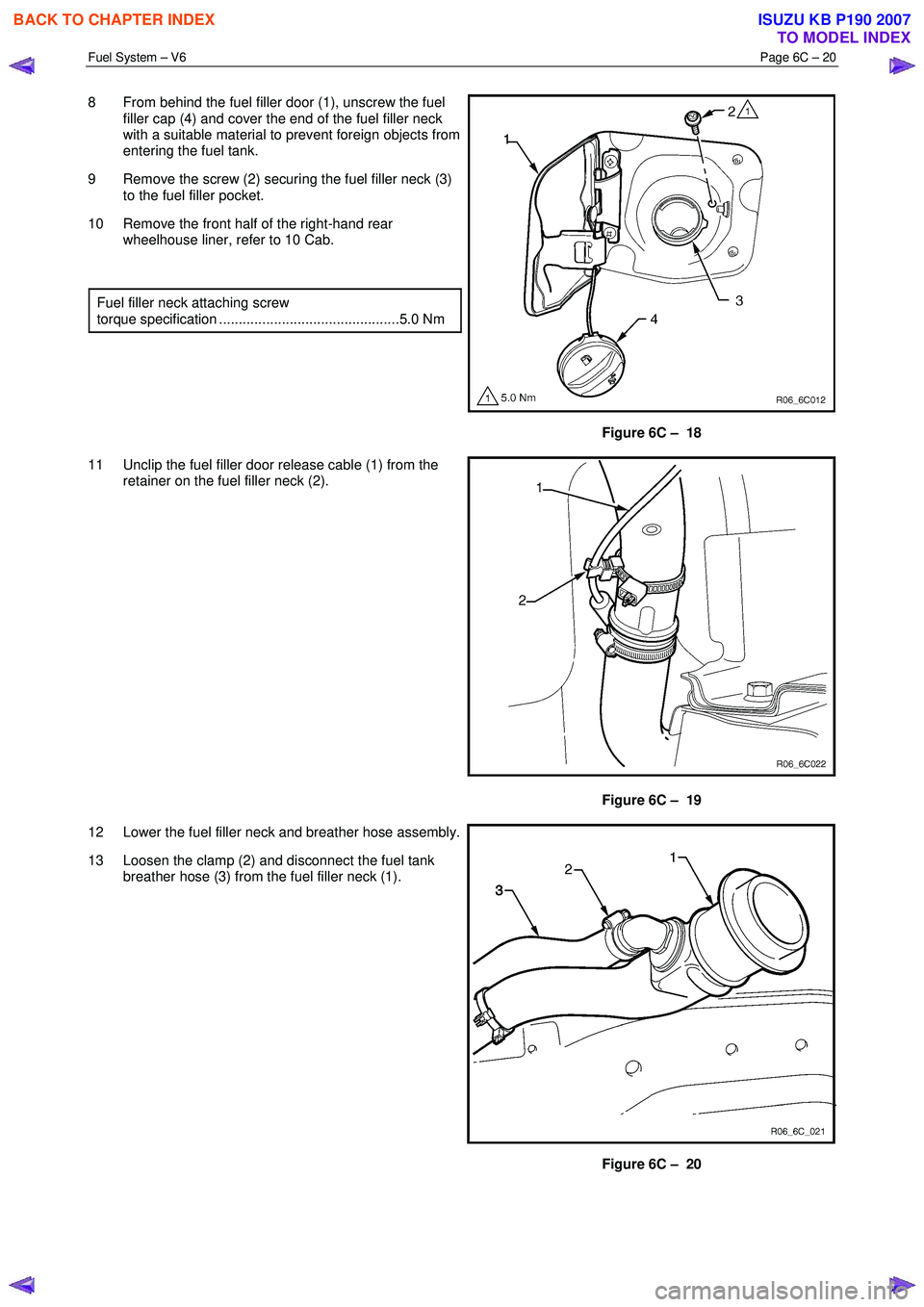
8 From behind the fuel filler door (1), unscrew the fuel
filler cap (4) and cover the end of the fuel filler neck
with a suitable material to prevent foreign objects from
entering the fuel tank.
9 Remove the screw (2) securing the fuel filler neck (3) to the fuel filler pocket.
10 Remove the front half of the right-hand rear wheelhouse liner, refer to 10 Cab.
Fuel filler neck attaching screw
torque specification ..............................................5.0 Nm
Figure 6C – 18
11 Unclip the fuel filler door release cable (1) from the retainer on the fuel filler neck (2).
Figure 6C – 19
12 Lower the fuel filler neck and breather hose assembly.
13 Loosen the clamp (2) and disconnect the fuel tank breather hose (3) from the fuel filler neck (1).
Figure 6C – 20
BACK TO CHAPTER INDEX
TO MODEL INDEX
ISUZU KB P190 2007
Page 3224 of 6020

Fuel System – V6 Page 6C – 22
Reinstall
Reinstallation of the fuel tank is the reverse of the removal procedure, noting the following:
1 Lift the fuel tank into position reinserting the fuel tank inlet and breather hoses into the body opening. Raise the fuel tank into place and rest the front of the tank on the crossmember.
2 Replace the fuel pump electrical connector, be sure to engage the locking tab.
3 Fit the fuel tank mounting straps in the following order, refer to Figure 6C – 17, a Loosely reattach the rear fuel tank mounting strap and bolt (8 & 9), refer to Figure 6C – 17.
b Loosely attach the front mounting strap and bolt (1 & 2), refer to Figure 6C – 17.
c Ensure that the fuel tank is located in the correct position then,
d Tighten the rear mounting strap bolt (8), Figure 6C – 17.
e Tighten the front mounting strap bolt (1), Figure 6C – 17.
4 Tighten all fuel tank mounting strap bolts to the correct torque specification.
Fuel tank mounting strap bolts
torque specification ............................................68.0 Nm
Install the fuel filter with the flow arrow on its
body pointing in the same direction as the
fuel flow to the front of the vehicle.
5 Install the disconnected quick-connect fittings to the fuel supply line at the front of the fuel tank and the evaporative line quick-connect fitting at the rear of the fuel tank. Refer to 4.1 Fuel Lines And Quick Connect Fittings, for the
correct component routeing.
6 Lower the vehicle to a comfortable working height and reinstall the clamp (1) to the fuel filler neck and reconnect the rubber fuel tank inlet hose (2) and tighten the clamp, refer to Figure 6C – 21.
7 Reinstall the fuel tank breather hose (3) to the fuel filler neck (1) and tighten the clamp (2), refer to Figure 6C – 20.
8 Clip the fuel filler door release cable (1) to the retainer on the fuel filler neck (2), refer to Figure 6C – 19.
9 Locate the fuel filler neck (3) to the filler pocket and attach with the securing screw (2), remove the cover material from the fuel filler neck inlet and refit the fuel filler cap (4), refer to Figure 6C – 18.
10 Reinstall the front half of the right-hand rear wheelhouse liner, refer to 10 Cab.
11 Before starting the vehicle, perform a fuel system leak test, refer to 3.3 Fuel Leak Test.
BACK TO CHAPTER INDEX
TO MODEL INDEX
ISUZU KB P190 2007
Page 3242 of 6020

Fuel System – V6 Page 6C – 40
7 Special Tools
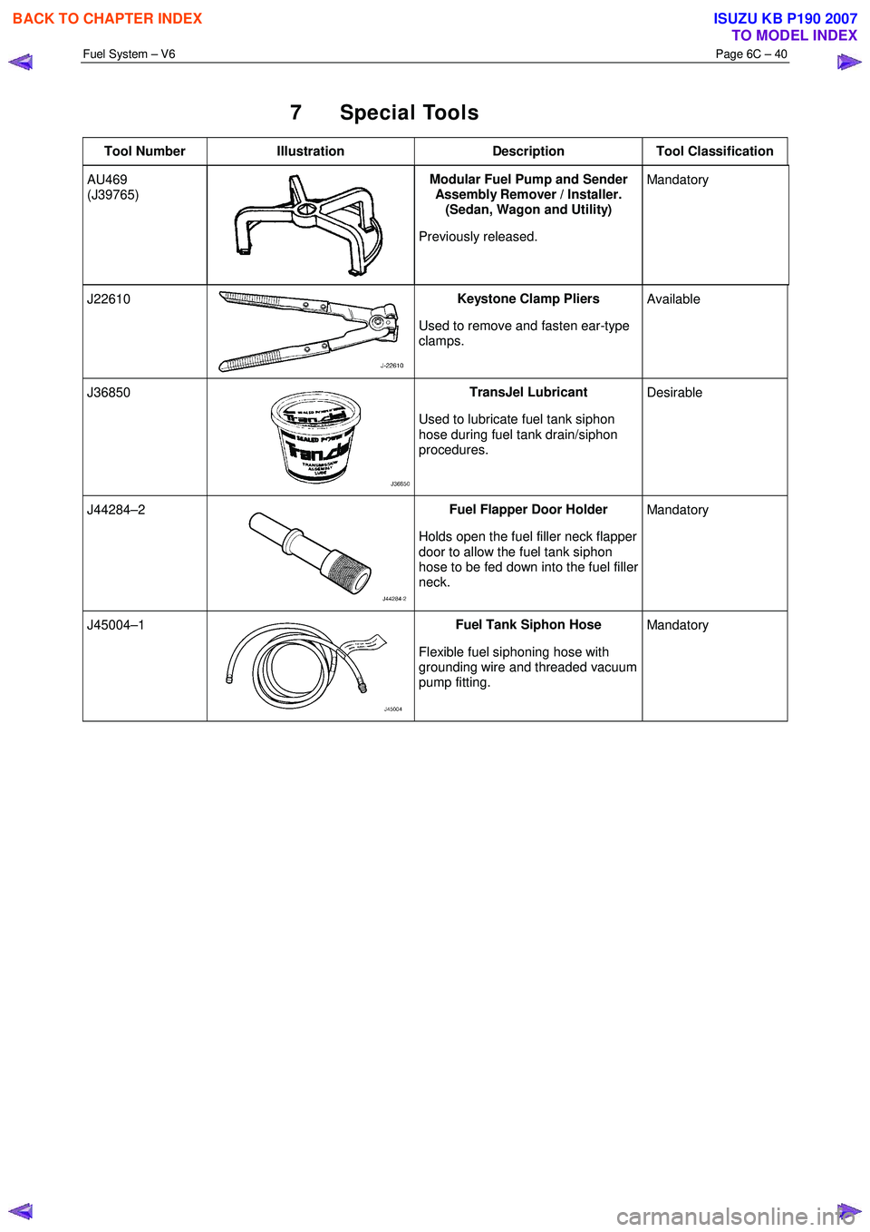
Tool Number Illustration Description Tool Classification
AU469
(J39765)
Modular Fuel Pump and Sender
Assembly Remover / Installer.
(Sedan, Wagon and Utility)
Previously released. Mandatory
J22610 Keystone Clamp Pliers
Used to remove and fasten ear-type
clamps. Available
J36850 TransJel Lubricant
Used to lubricate fuel tank siphon
hose during fuel tank drain/siphon
procedures. Desirable
J44284–2 Fuel Flapper Door Holder
Holds open the fuel filler neck flapper
door to allow the fuel tank siphon
hose to be fed down into the fuel filler
neck. Mandatory
J45004–1 Fuel Tank Siphon Hose
Flexible fuel siphoning hose with
grounding wire and threaded vacuum
pump fitting. Mandatory
BACK TO CHAPTER INDEX
TO MODEL INDEX
ISUZU KB P190 2007