Circuit ISUZU KB P190 2007 Workshop Repair Manual
[x] Cancel search | Manufacturer: ISUZU, Model Year: 2007, Model line: KB P190, Model: ISUZU KB P190 2007Pages: 6020, PDF Size: 70.23 MB
Page 1624 of 6020
ENGINE CONTROL SYSTEM (4JK1/4JJ1) 6E-7
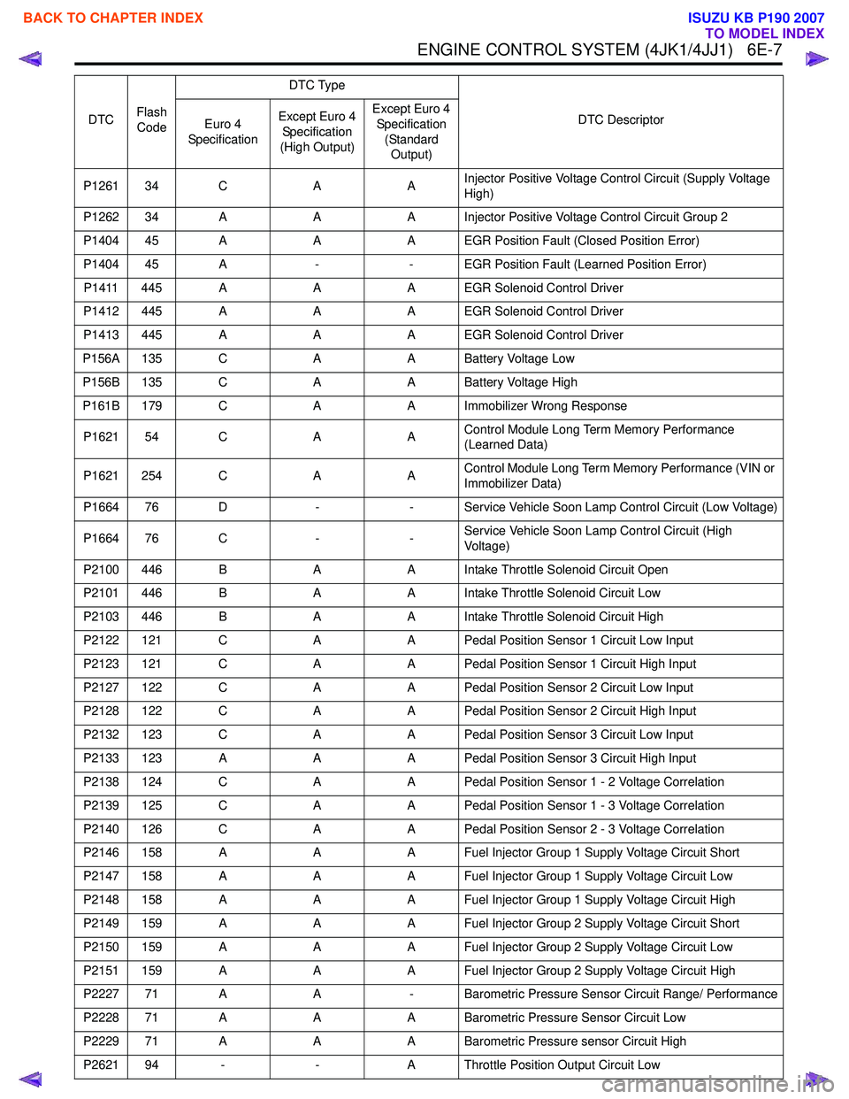
P1261 34 CAAInjector Positive Voltage Control Circuit (Supply Voltage
High)
P1262 34 A AA Injector Positive Voltage Control Circuit Group 2
P1404 45 A AA EGR Position Fault (Closed Position Error)
P1404 45 A -- EGR Position Fault (Learned Position Error)
P1411 445 A AA EGR Solenoid Control Driver
P1412 445 A AA EGR Solenoid Control Driver
P1413 445 A AA EGR Solenoid Control Driver
P156A 135 C AA Battery Voltage Low
P156B 135 C AA Battery Voltage High
P161B 179 C AA Immobilizer Wrong Response
P1621 54 C AAControl Module Long Term Memory Performance
(Learned Data)
P1621 254 C AAControl Module Long Term Memory Performance (VIN or
Immobilizer Data)
P1664 76 D -- Service Vehicle Soon Lamp Control Circuit (Low Voltage)
P1664 76 C --Service Vehicle Soon Lamp Control Circuit (High
Voltage)
P2100 446 B AA Intake Throttle Solenoid Circuit Open
P2101 446 B AA Intake Throttle Solenoid Circuit Low
P2103 446 B AA Intake Throttle Solenoid Circuit High
P2122 121 C AA Pedal Position Sensor 1 Circuit Low Input
P2123 121 C AA Pedal Position Sensor 1 Circuit High Input
P2127 122 C AA Pedal Position Sensor 2 Circuit Low Input
P2128 122 C AA Pedal Position Sensor 2 Circuit High Input
P2132 123 C AA Pedal Position Sensor 3 Circuit Low Input
P2133 123 A AA Pedal Position Sensor 3 Circuit High Input
P2138 124 C AA Pedal Position Sensor 1 - 2 Voltage Correlation
P2139 125 C AA Pedal Position Sensor 1 - 3 Voltage Correlation
P2140 126 C AA Pedal Position Sensor 2 - 3 Voltage Correlation
P2146 158 A AA Fuel Injector Group 1 Supply Voltage Circuit Short
P2147 158 A AA Fuel Injector Group 1 Supply Voltage Circuit Low
P2148 158 A AA Fuel Injector Group 1 Supply Voltage Circuit High
P2149 159 A AA Fuel Injector Group 2 Supply Voltage Circuit Short
P2150 159 A AA Fuel Injector Group 2 Supply Voltage Circuit Low
P2151 159 A AA Fuel Injector Group 2 Supply Voltage Circuit High
P2227 71 A A- Barometric Pressure Sensor Circuit Range/ Performance
P2228 71 A AA Barometric Pressure Sensor Circuit Low
P2229 71 A AA Barometric Pressure sensor Circuit High
P2621 94 - -A Throttle Position Output Circuit Low
DTC
Flash
Code DTC Type
DTC Descriptor
Euro 4
Specification Except Euro 4
Specification
(High Output) Except Euro 4
Specification (Standard Output)
BACK TO CHAPTER INDEX
TO MODEL INDEX
ISUZU KB P190 2007
Page 1625 of 6020
6E-8 ENGINE CONTROL SYSTEM (4JK1/4JJ1)
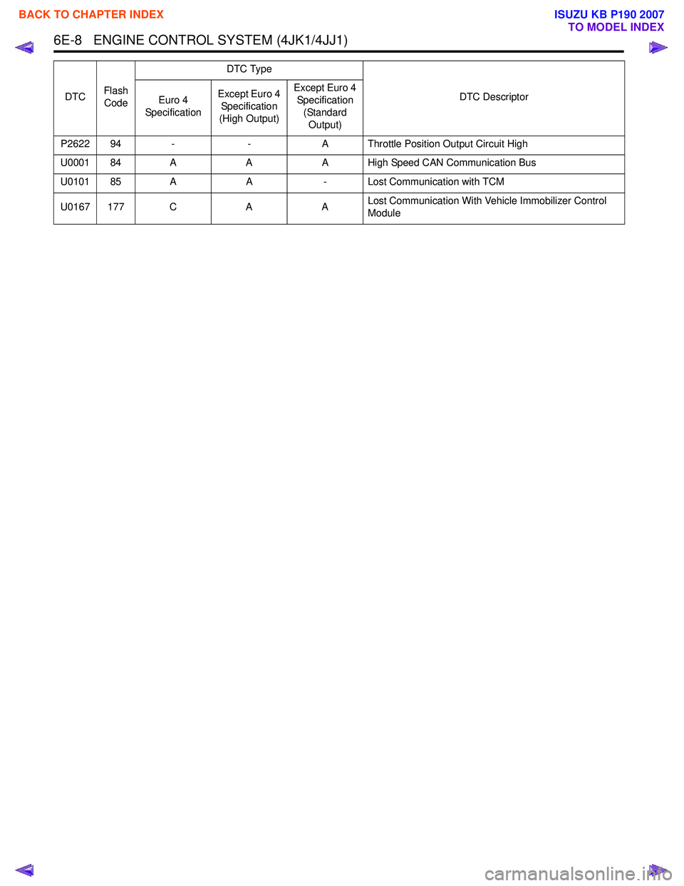
P2622 94 --A Throttle Position Output Circuit High
U0001 84 A AA High Speed CAN Communication Bus
U0101 85 A A- Lost Communication with TCM
U0167 177 C AALost Communication With Vehicle Immobilizer Control
Module
DTC
Flash
Code DTC Type
DTC Descriptor
Euro 4
Specification Except Euro 4
Specification
(High Output) Except Euro 4
Specification (Standard Output)
BACK TO CHAPTER INDEX
TO MODEL INDEX
ISUZU KB P190 2007
Page 1661 of 6020
6E-44 ENGINE CONTROL SYSTEM (4JK1/4JJ1)
Diagnostic Starting Point - Engine Controls
Begin the system diagnosis with Diagnostic System
Check - Engine Controls. The Diagnostic System
Check - Engine Controls will provide the following
information:
• The identification of the control modules which command the system.
• The ability of the control modules to communicate through the serial data circuit.
• The identification of any stored diagnostic trouble codes (DTCs) and the their statuses.
The use of the Diagnostic System Check - Engine
Controls will identify the correct procedure for
diagnosing the system and where the procedure is
located.
Important: Engine Control System Check Sheet must
be used to verify the complaint vehicle, you need to
know the correct (normal) operating behavior of the
system and verify that the customer complaint is a valid
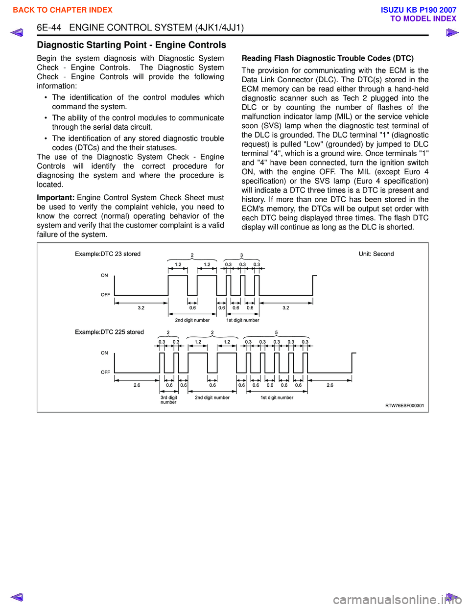
failure of the system. Reading Flash Diagnostic Trouble Codes (DTC)
The provision for communicating with the ECM is the
Data Link Connector (DLC). The DTC(s) stored in the
ECM memory can be read either through a hand-held
diagnostic scanner such as Tech 2 plugged into the
DLC or by counting the number of flashes of the
malfunction indicator lamp (MIL) or the service vehicle
soon (SVS) lamp when the diagnostic test terminal of
the DLC is grounded. The DLC terminal "1" (diagnostic
request) is pulled "Low" (grounded) by jumped to DLC
terminal "4", which is a ground wire. Once terminals "1"
and "4" have been connected, turn the ignition switch
ON, with the engine OFF. The MIL (except Euro 4
specification) or the SVS lamp (Euro 4 specification)
will indicate a DTC three times is a DTC is present and
history. If more than one DTC has been stored in the
ECM's memory, the DTCs will be output set order with
each DTC being displayed three times. The flash DTC
display will continue as long as the DLC is shorted.
RTW76ESF000301
ON
OFF
ON
OFF
1.2
3.2
2.62.6
2nd digit number1st digit number
3.20.6 2
1.2
0.60.60.6
0.30.30.3
0.30.30.30.30.3
Example:DTC 23 stored
Unit: Second
Example:DTC 225 stored
3rd digit
number 2nd digit number1st digit number
0.60.60.60.60.60.60.60.6
3
0.30.31.21.2
2
25
BACK TO CHAPTER INDEX
TO MODEL INDEX
ISUZU KB P190 2007
Page 1662 of 6020
ENGINE CONTROL SYSTEM (4JK1/4JJ1) 6E-45
Diagnostic System Check - Engine Controls
Description
The Diagnostic System Check - Engine Controls is an
organized approach to identifying a condition that is
created by a malfunction in the electronic engine
control system. The Diagnostic System Check must be
the starting point for any driveability concern. The
Diagnostic System Check directs the service technician
to the next logical step in order to diagnose the
concern. Understanding and correctly using the
diagnostic table reduces diagnostic time, and prevents
the replacement of good parts.
Test Description
The numbers below refer to the step numbers on the
diagnostic table.
2. Lack of communication may be because of a partial
or a total malfunction of the serial data circuit.
7. The presence of DTCs which begin with U, indicate
that some other module is not communicating.
10. If there are other modules with DTCs set, refer to
the DTC list. The DTC list directs you to the appropriate
diagnostic procedure. If the control module stores
multiple DTCs, diagnose the DTCs in the following
order:
• Component level DTCs, such as sensor DTCs, solenoid DTCs, actuator DTCs, and relay DTCs.
Diagnose the multiple DTCs within this category in
numerical order. Begin with the lowest numbered
DTC, unless the diagnostic table directs you
otherwise. Diagnostic System Check Engine Controls
Important:
• DO NOT perform this diagnostic if there is not a driveability concern, unless another procedure
directs you to this diagnostic.
• Before you proceed with diagnosis, search for applicable service bulletins.
• Unless a diagnostic procedure instructs you, DO NOT clear the DTCs.
• If there is a condition with the starting system, refer to the starting system section in the engine
mechanical.
• Ensure the battery has a full charge.
• Ensure the battery cables (+) (-) are clean and tight.
• Ensure the ECM grounds are clean, tight, and in the correct location.
• Ensure the ECM harness connectors are clean and correctly connected. DO NOT attempt to
crank the engine with ECM harness connectors
disconnect.
• Ensure the ECM terminals are clean and correctly mating.
• Ensure the fuel injector ID code data is correctly programmed in to the ECM.
• Ensure the immobilizer security information is correctly programmed into the ECM and
immobilizer control unit (ICU).
• If there are fuel system DTC’s (P0087, P0088, P0089, P0093, P1093 or P1094), diagnose sensor
DTCs, solenoid DTCs, actuator DTCs and relay
DTCs first.
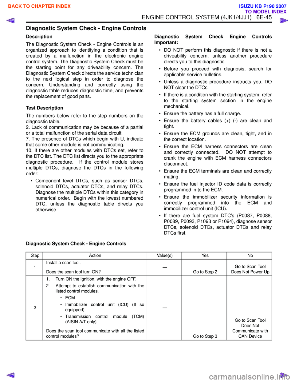
Diagnostic System Check - Engine Controls
Step Action Value(s)Yes No
1 Install a scan tool.
Does the scan tool turn ON? —
Go to Step 2 Go to Scan Tool
Does Not Power Up
2 1. Turn ON the ignition, with the engine OFF.
2. Attempt to establish communication with the listed control modules.
•ECM
• Immobilizer control unit (ICU) (If so equipped)
• Transmission control module (TCM) (AISIN A/T only)
Does the scan tool communicate with all the listed
control modules? —
Go to Step 3 Go to Scan Tool
Does Not
Communicate with CAN Device
BACK TO CHAPTER INDEX
TO MODEL INDEX
ISUZU KB P190 2007
Page 1670 of 6020
ENGINE CONTROL SYSTEM (4JK1/4JJ1) 6E-53
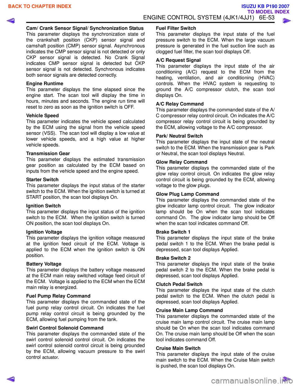
Cam/ Crank Sensor Signal/ Synchronization Status
This parameter displays the synchronization state of
the crankshaft position (CKP) sensor signal and
camshaft position (CMP) sensor signal. Asynchronous
indicates the CMP sensor signal is not detected or only
CKP sensor signal is detected. No Crank Signal
indicates CMP sensor signal is detected but CKP
sensor signal is not detected. Synchronous indicates
both sensor signals are detected correctly.
Engine Runtime
This parameter displays the time elapsed since the
engine start. The scan tool will display the time in
hours, minutes and seconds. The engine run time will
reset to zero as soon as the ignition switch is OFF.
Vehicle Speed
This parameter indicates the vehicle speed calculated
by the ECM using the signal from the vehicle speed
sensor (VSS). The scan tool will display a low value at
lower vehicle speeds, and a high value at higher
vehicle speeds.
Transmission Gear
This parameter displays the estimated transmission
gear position as calculated by the ECM based on
inputs from the vehicle speed and the engine speed.
Starter Switch
This parameter displays the input status of the starter
switch to the ECM. When the ignition switch is turned at
START position, the scan tool displays On.
Ignition Switch
This parameter displays the input status of the ignition
switch to the ECM. When the ignition switch is turned
ON position, the scan tool displays On.
Ignition Voltage
This parameter displays the ignition voltage measured
at the ignition feed circuit of the ECM. Voltage is
applied to the ECM when the ignition switch is ON
position.
Battery Voltage
This parameter displays the battery voltage measured
at the ECM main relay switched voltage feed circuit of
the ECM. Voltage is applied to the ECM when the ECM
main relay is energized.
Fuel Pump Relay Command
This parameter displays the commanded state of the
fuel pump relay control circuit. On indicates the fuel
pump relay control circuit is being grounded by the
ECM, allowing fuel pumping from the tank.
Swirl Control Solenoid Command
This parameter displays the commanded state of the
swirl control solenoid control circuit. On indicates the
swirl control solenoid control circuit is being grounded
by the ECM, allowing vacuum pressure to the swirl
control
actuator. Fuel Filter Switch
This parameter displays the input state of the fuel
pressure switch to the ECM. When the large vacuum
pressure is generated in the fuel suction line such as
clogged fuel filter, the scan tool displays Off.
A/C Request Signal
This parameter displays the input state of the air
conditioning (A/C) request to the ECM from the
heating, ventilation, and air conditioning (HVAC)
controls. When the HVAC system is requesting to
ground the A/C compressor clutch, the scan tool
displays On.
A/C Relay Command
This parameter displays the commanded state of the A/
C compressor relay control circuit. On indicates the A/C
compressor relay control circuit is being grounded by
the ECM, allowing voltage to the A/C compressor.
Park/ Neutral Switch
This parameter displays the input state of the neutral
switch to the ECM. When the transmission gear is Park
or Neutral, the scan tool displays Neutral.
Glow Relay Command
This parameter displays the commanded state of the
glow relay control circuit. On indicates the glow relay
control circuit is being grounded by the ECM, allowing
voltage to the glow plugs.
Glow Plug Lamp Command
This parameter displays the commanded state of the
glow indicator lamp control circuit. The glow indicator
lamp should be On when the scan tool indicates
command On. The glow indicator lamp should be Off
when the scan tool indicates command Off.
Brake Switch 1
This parameter displays the input state of the brake
pedal switch 1 to the ECM. When the brake pedal is
depressed, scan tool displays Applied.
Brake Switch 2
This parameter displays the input state of the brake
pedal switch 2 to the ECM. When the brake pedal is
depressed, scan tool displays Applied.
Clutch Pedal Switch
This parameter displays the input state of the clutch
pedal switch to the ECM. When the clutch pedal is
depressed, scan tool displays Applied.
Cruise Main Lamp Command
This parameter displays the commanded state of the
cruise main lamp control circuit. The cruise main lamp
should be On when the scan tool indicates command
On. The cruise main lamp should be Off when the scan
tool indicates command Off.
Cruise Main Switch
This parameter displays the input state of the cruise
main switch to the ECM. When the Cruise Main switch
is pushed, the scan tool displays On.
BACK TO CHAPTER INDEX
TO MODEL INDEX
ISUZU KB P190 2007
Page 1671 of 6020
6E-54 ENGINE CONTROL SYSTEM (4JK1/4JJ1)
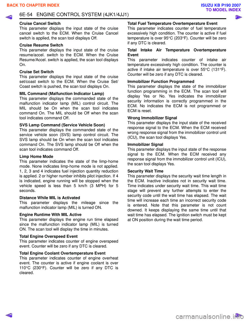
Cruise Cancel Switch
This parameter displays the input state of the cruise
cancel switch to the ECM. When the Cruise Cancel
switch is applied, the scan tool displays Off.
Cruise Resume Switch
This parameter displays the input state of the cruise
resume/accel. switch to the ECM. When the Cruise
Resume/Accel. switch is applied, the scan tool displays
On.
Cruise Set Switch
This parameter displays the input state of the cruise
set/coast switch to the ECM. When the Cruise Set/
Coast switch is pushed, the scan tool displays On.
MIL Command (Malfunction Indicator Lamp)
This parameter displays the commanded state of the
malfunction indicator lamp (MIL) control circuit. The
MIL should be On when the scan tool indicates
command On. The MIL should be Off when the scan
tool indicates command Off.
SVS Lamp Command (Service Vehicle Soon)
This parameter displays the commanded state of the
service vehicle soon (SVS) lamp control circuit. The
SVS lamp should be On when the scan tool indicates
command On. The SVS lamp should be Off when the
scan tool indicates command Off.
Limp Home Mode
This parameter indicates the state of the limp-home
mode. None indicates limp-home mode is not applied.
1, 2, 3 and 4 indicates fuel injection quantity reduction
is applied. 2 or higher number inhibits pilot injection. If 4
is indicated, engine running will be stopped when the
vehicle speed is less than 5 km/h (3 MPH) for 5
seconds.
Distance While MIL is Activated
This parameter displays the mileage since the
malfunction indicator lamp (MIL) is turned ON.
Engine Runtime With MIL Active
This parameter displays the engine run time elapsed
since the malfunction indicator lamp (MIL) is turned
ON. The scan tool will display the time in minutes.
Total Engine Overspeed Event
This parameter indicates counter of engine overspeed
event. Counter will be zero if any DTC is cleared.
Total Engine Coolant Overtemperature Event
This parameter indicates counter of engine overheat
event. The counter is active if engine coolant is over
11 0 °C (230 °F). Counter will be zero if any DTC is
cleared. Total Fuel Temperature Overtemperature Event
This parameter indicates counter of fuel temperature
excessively high condition. The counter is active if fuel
temperature is over 95 °C (203 °F). Counter will be zero
if any DTC is cleared.
Total Intake Air Temperature Overtemperature
Event
This parameter indicates counter of intake air
temperature excessively high condition. The counter is
active if intake air temperature is over 55 °C (131 °F).
Counter will be zero if any DTC is cleared.
Immobilizer Function Programmed
This parameter displays the state of the immobilizer
function programming in the ECM. The scan tool will
display Yes or No. Yes indicates the immobilizer
security information is correctly programmed in the
ECM. No indicates the ECM is not programmed or
ECM is reset.
Wrong Immobilizer Signal
This parameter displays the input state of the received
response signal to the ECM. When the ECM received
wrong response signal from the immobilizer control unit
(ICU), the scan tool displays Yes.
Immobilizer Signal
This parameter displays the input state of the response
signal to the ECM. When the ECM received any
response signal from the immobilizer control unit (ICU),
the scan tool displays Yes.
Security Wait Time
This parameter displays the security wait time length in
the ECM. Inactive indicates not in security wait time.
Time indicates under security wait time. This wait time
stage will prevent any further attempts to enter the
security code until the wait time has elapsed. The wait
time will increase each time an incorrect security code
is entered. Note that this parameter is not count
downed. It keeps displaying the same time until that
wait time has elapsed. The ignition switch must be kept
at ON position during the wait time period.
BACK TO CHAPTER INDEX
TO MODEL INDEX
ISUZU KB P190 2007
Page 1672 of 6020
ENGINE CONTROL SYSTEM (4JK1/4JJ1) 6E-55
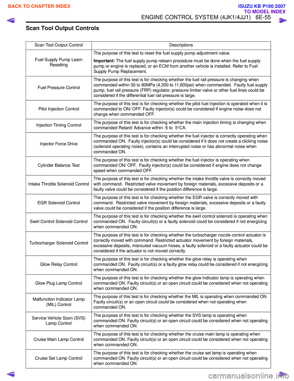
Scan Tool Output Controls
Scan Tool Output ControlDescriptions
Fuel Supply Pump Learn Resetting The purpose of this test to reset the fuel supply pump adjustment value.
Important: The fuel supply pump relearn procedure must be done when the fuel supply
pump or engine is replaced, or an ECM from another vehicle is installed. Refer to Fuel
Supply Pump Replacement.
Fuel Pressure Control The purpose of this test is for checking whether the fuel rail pressure is changing when
commanded within 30 to 80MPa (4,350 to 11,600psi) when commanded. Faulty fuel supply
pump, fuel rail pressure (FRP) regulator, pressure limiter valve or other fuel lines could be
considered if the differential fuel rail pressure is large.
Pilot Injection Control The purpose of this test is for checking whether the pilot fuel injection is operated when it is
commanded to ON/ OFF. Faulty injector(s) could be considered if engine noise does not
change when commanded OFF.
Injection Timing Control The purpose of this test is for checking whether the main injection timing is changing when
commanded Retard/ Advance within -5 to 5 °CA.
Injector Force Drive The purpose of this test is for checking whether the fuel injector is correctly operating when
commanded ON. Faulty injector(s) could be considered if it does not create a clicking noise
(solenoid operating noise), contains an interrupted noise or has abnormal noise when
commanded ON.
Cylinder Balance Test The purpose of this test is for checking whether the fuel injector is operating when
commanded ON/ OFF. Faulty injector(s) could be considered if engine does not change
speed when commanded OFF.
Intake Throttle Solenoid Control The purpose of this test is for checking whether the intake throttle valve is correctly moved
with command. Restricted valve movement by foreign materials, excessive deposits or a
faulty valve could be considered if the position difference is large.
EGR Solenoid Control The purpose of this test is for checking whether the EGR valve is correctly moved with
command. Restricted valve movement by foreign materials, excessive deposits or a faulty
valve could be considered if the position difference is large.
Swirl Control Solenoid Control The purpose of this test is for checking whether the swirl control solenoid is operating when
commanded ON. Faulty circuit(s) or a faulty solenoid could be considered if not energizing
when commanded ON.
Turbocharger Solenoid Control The purpose of this test is for checking whether the turbocharger nozzle control actuator is
correctly moved with command. Restricted actuator movement by foreign materials,
excessive deposits, misrouted vacuum hoses, a faulty solenoid or a faulty actuator could be
considered if the actuator is not moved correctly.
Glow Relay Control The purpose of this test is for checking whether the glow relay is operating when
commanded ON. Faulty circuit(s) or a faulty glow relay could be considered if not energizing
when commanded ON.
Glow Plug Lamp Control The purpose of this test is for checking whether the glow indicator lamp is operating when
commanded ON. Faulty circuit(s) or an open circuit could be considered when not operating
when commanded ON.
Malfunction Indicator Lamp (MIL) Control The purpose of this test is for checking whether the MIL is operating when commanded ON.
Faulty circuit(s) or an open circuit could be considered when not operating when
commanded ON.
Service Vehicle Soon (SVS) Lamp Control The purpose of this test is for checking whether the SVS lamp is operating when
commanded ON. Faulty circuit(s) or an open circuit could be considered when not operating
when commanded ON.
Cruise Main Lamp Control The purpose of this test is for checking whether the cruise main lamp is operating when
commanded ON. Faulty circuit(s) or an open circuit could be considered when not operating
when commanded ON.
Cruise Set Lamp Control The purpose of this test is for checking whether the cruise set lamp is operating when
commanded ON. Faulty circuit(s) or an open circuit could be considered when not operating
when commanded ON.
BACK TO CHAPTER INDEX
TO MODEL INDEX
ISUZU KB P190 2007
Page 1673 of 6020
6E-56 ENGINE CONTROL SYSTEM (4JK1/4JJ1)
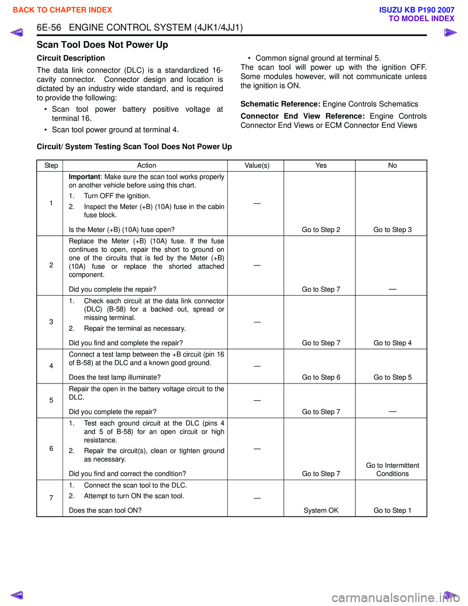
Scan Tool Does Not Power Up
Circuit Description
The data link connector (DLC) is a standardized 16-
cavity connector. Connector design and location is
dictated by an industry wide standard, and is required
to provide the following:
• Scan tool power battery positive voltage at terminal 16.
• Scan tool power ground at terminal 4. • Common signal ground at terminal 5.
The scan tool will power up with the ignition OFF.
Some modules however, will not communicate unless
the ignition is ON.
Schematic Reference: Engine Controls Schematics
Connector End View Reference: Engine Controls
Connector End Views or ECM Connector End Views
Circuit/ System Testing Scan Tool Does Not Power Up
Step Action Value(s)Yes No
1 Important
: Make sure the scan tool works properly
on another vehicle before using this chart.
1. Turn OFF the ignition.
2. Inspect the Meter (+B) (10A) fuse in the cabin fuse block.
Is the Meter (+B) (10A) fuse open? —
Go to Step 2 Go to Step 3
2 Replace the Meter (+B) (10A) fuse. If the fuse
continues to open, repair the short to ground on
one of the circuits that is fed by the Meter (+B)
(10A) fuse or replace the shorted attached
component.
Did you complete the repair? —
Go to Step 7
—
31. Check each circuit at the data link connector
(DLC) (B-58) for a backed out, spread or
missing terminal.
2. Repair the terminal as necessary.
Did you find and complete the repair? —
Go to Step 7 Go to Step 4
4 Connect a test lamp between the +B circuit (pin 16
of B-58) at the DLC and a known good ground.
Does the test lamp illuminate? —
Go to Step 6 Go to Step 5
5 Repair the open in the battery voltage circuit to the
DLC.
Did you complete the repair? —
Go to Step 7
—
61. Test each ground circuit at the DLC (pins 4
and 5 of B-58) for an open circuit or high
resistance.
2. Repair the circuit(s), clean or tighten ground as necessary.
Did you find and correct the condition? —
Go to Step 7 Go to Intermittent
Conditions
7 1. Connect the scan tool to the DLC.
2. Attempt to turn ON the scan tool.
Does the scan tool ON? —
System OK Go to Step 1
BACK TO CHAPTER INDEX
TO MODEL INDEX
ISUZU KB P190 2007
Page 1674 of 6020
ENGINE CONTROL SYSTEM (4JK1/4JJ1) 6E-57
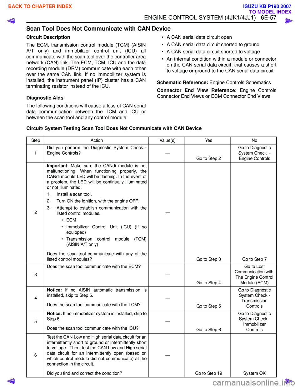
Scan Tool Does Not Communicate with CAN Device
Circuit Description
The ECM, transmission control module (TCM) (AISIN
A/T only) and immobilizer control unit (ICU) all
communicate with the scan tool over the controller area
network (CAN) link. The ECM, TCM, ICU and the data
recording module (DRM) communicate with each other
over the same CAN link. If no immobilizer system is
installed, the instrument panel (IP) cluster has a CAN
terminating resistor instead of the ICU.
Diagnostic Aids
The following conditions will cause a loss of CAN serial
data communication between the TCM and ICU or
between the scan tool and any control module: • A CAN serial data circuit open
• A CAN serial data circuit shorted to ground
• A CAN serial data circuit shorted to voltage
• An internal condition within a module or connector on the CAN serial data circuit, that causes a short
to voltage or ground to the CAN serial data circuit
Schematic Reference: Engine Controls Schematics
Connector End View Reference: Engine Controls
Connector End Views or ECM Connector End Views
Circuit/ System Testing Scan Tool Does Not Communicate with CAN Device
Step Action Value(s)Yes No
1 Did you perform the Diagnostic System Check -
Engine Controls? —
Go to Step 2 Go to Diagnostic
System Check - Engine Controls
2 Important
: Make sure the CANdi module is not
malfunctioning. When functioning properly, the
CANdi module LED will be flashing. In the event of
a problem, the LED will be continually illuminated
or not illuminated.
1. Install a scan tool.
2. Turn ON the ignition, with the engine OFF.
3. Attempt to establish communication with the listed control modules.
•ECM
• Immobilizer Control Unit (ICU) (If so equipped)
• Transmission control module (TCM) (AISIN A/T only)
Does the scan tool communicate with any of the
listed control modules? —
Go to Step 3 Go to Step 7
3 Does the scan tool communicate with the ECM?
—
Go to Step 4 Go to Lost
Communication with
The Engine Control Module (ECM)
4 Notice:
If no AISIN automatic transmission is
installed, skip to Step 5.
Does the scan tool communicate with the TCM? —
Go to Step 5 Go to Diagnostic
System Check -
Transmission Controls
5 Notice:
If no immobilizer system is installed, skip to
Step 6.
Does the scan tool communicate with the ICU? —
Go to Step 6 Go to Diagnostic
System Check -
Immobilizer Controls
6 Test the CAN Low and High serial data circuit for an
intermittently short to ground or intermittently short
to voltage. Then, test the CAN Low and High serial
data circuit for an intermittently open (based on
which control module did not communicate) at the
connection in the circuit.
Did you find and correct the condition? —
Go to Step 19 System OK
BACK TO CHAPTER INDEX
TO MODEL INDEX
ISUZU KB P190 2007
Page 1676 of 6020
ENGINE CONTROL SYSTEM (4JK1/4JJ1) 6E-59
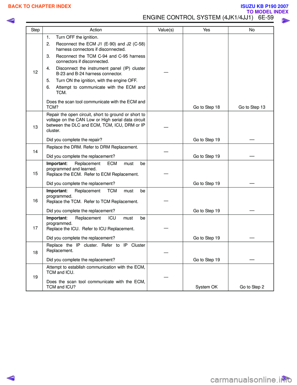
121. Turn OFF the ignition.
2. Reconnect the ECM J1 (E-90) and J2 (C-58) harness connectors if disconnected.
3. Reconnect the TCM C-94 and C-95 harness connectors if disconnected.
4. Disconnect the instrument panel (IP) cluster B-23 and B-24 harness connector.
5. Turn ON the ignition, with the engine OFF.
6. Attempt to communicate with the ECM and TCM.
Does the scan tool communicate with the ECM and
TCM? —
Go to Step 18 Go to Step 13
13 Repair the open circuit, short to ground or short to
voltage on the CAN Low or High serial data circuit
between the DLC and ECM, TCM, ICU, DRM or IP
cluster.
Did you complete the repair? —
Go to Step 19
—
14Replace the DRM. Refer to DRM Replacement.
Did you complete the replacement? —
Go to Step 19—
15Important
: Replacement ECM must be
programmed and learned.
Replace the ECM. Refer to ECM Replacement.
Did you complete the replacement? —
Go to Step 19
—
16Important
: Replacement TCM must be
programmed.
Replace the TCM. Refer to TCM Replacement.
Did you complete the replacement? —
Go to Step 19
—
17Important
: Replacement ICU must be
programmed.
Replace the ICU. Refer to ICU Replacement.
Did you complete the replacement? —
Go to Step 19
—
18Replace the IP cluster. Refer to IP Cluster
Replacement.
Did you complete the replacement? —
Go to Step 19
—
19Attempt to establish communication with the ECM,
TCM and ICU.
Does the scan tool communicate with the ECM,
TCM and ICU? —
System OK Go to Step 2
Step
Action Value(s)Yes No
BACK TO CHAPTER INDEX
TO MODEL INDEX
ISUZU KB P190 2007