open hood ISUZU KB P190 2007 Workshop Owner's Manual
[x] Cancel search | Manufacturer: ISUZU, Model Year: 2007, Model line: KB P190, Model: ISUZU KB P190 2007Pages: 6020, PDF Size: 70.23 MB
Page 5291 of 6020

ELECTRICAL-BODY AND CHASSIS 8A-353
REMOVAL AND INSTALLATION
RTW 780SH001701
This illustration is based on RHD model
METER ASSEMBLY
Removal
1. Meter Cluster Assembly
• Refer to the removal steps of “INSTRUMENT PANEL” in
Section 10 “CAB”
2. Meter Assembly • Remove three screws of the meter assembly.
• Disconnect the meter connectors.
Installation
Follow the removal procedure in the reverse order to install the
meter.
Pay close attention to the important points mentioned in the
following paragraphs.
Connector
Be absolutely sure that the meter connectors are securely
connected.
This will prevent a poor contact and an open circuit.
Wire Harness
Do not pinch the wire harness between the cluster and the
meter hood during the meter assembly installation procedure.
W ire damage will result.
BACK TO CHAPTER INDEX
TO MODEL INDEXISUZU KB P190 2007
Page 5787 of 6020
CAB 10-29
Important Operations
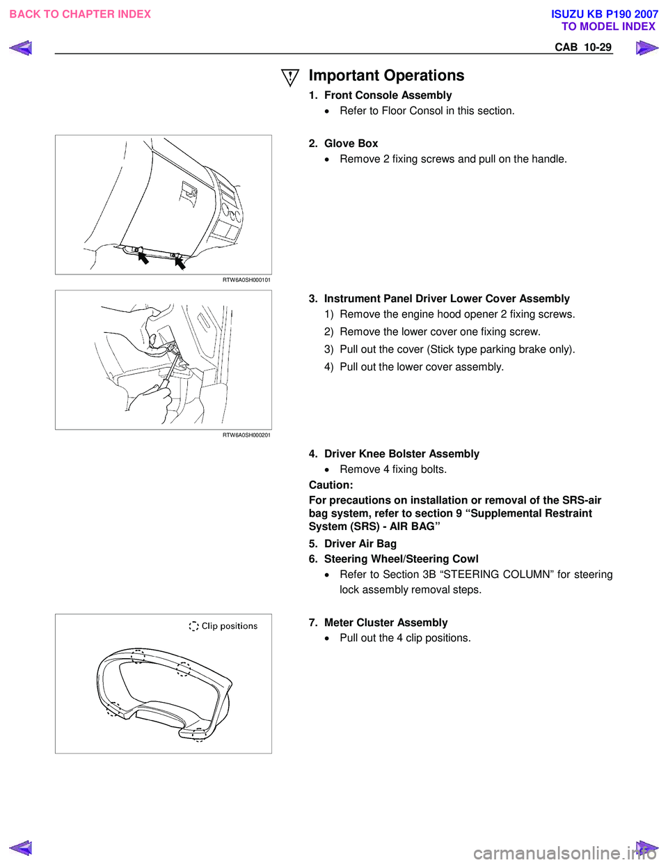
1. Front Console Assembly • Refer to Floor Consol in this section.
RTW 6A0SH000101
2. Glove Box
• Remove 2 fixing screws and pull on the handle.
RTW 6A0SH000201
3. Instrument Panel Driver Lower Cover Assembly
1) Remove the engine hood opener 2 fixing screws.
2) Remove the lower cover one fixing screw.
3) Pull out the cover (Stick type parking brake only).
4) Pull out the lower cover assembly.
4. Driver Knee Bolster Assembly
• Remove 4 fixing bolts.
Caution:
For precautions on installation or removal of the SRS-air
bag system, refer to section 9 “Supplemental Restraint
System (SRS) - AIR BAG”
5. Driver Air Bag
6. Steering Wheel/Steering Cowl • Refer to Section 3B “STEERING COLUMN” for steering
lock assembly removal steps.
7. Meter Cluster Assembly
• Pull out the 4 clip positions.
BACK TO CHAPTER INDEX TO MODEL INDEX
ISUZU KB P190 2007
Page 5956 of 6020
11B-2 ANTITHEFT SYSTEM
Service Precaution
WARNING: THIS VEHICLE HAS A SUPPLEMENTAL
RESTRAINT SYSTEM (SRS). REFER TO THE SRS
COMPONENT AND WIRING LOCATION VIEW IN
ORDER TO DETERMINE WHETHER YOU ARE
PERFORMING SERVICE ON OR NEAR THE SRS
COMPONENTS OR THE SRS WIRING. WHEN YOU
ARE PERFORMING SERVICE ON OR NEAR THE
SRS COMPONENTS OR THE SRS WIRING, REFER
TO THE SRS SERVICE INFORMATION. FAILURE TO
FOLLOW WARNINGS COULD RESULT IN
POSSIBLE AIR BAG DEPLOYMENT, PERSONAL
INJURY, OR OTHERWISE UNNEEDED SRS SYSTEM
REPAIRS.
CAUTION: Always use the correct fastener in the
proper location. When you replace a fastener, use
ONLY the exact part number for that application.
ISUZU will call out those fasteners that require a
replacement after removal. ISUZU will also call out
the fasteners that require thread lockers or thread
sealant. UNLESS OTHERWISE SPECIFIED, do not
use supplemental coatings (Paints, greases, or
other corrosion inhibitors) on threaded fasteners or
fastener joint interfaces. Generally, such coatings
adversely affect the fastener torque and the joint
clamping force, and may damage the fastener.
When you install fasteners, use the correct
tightening sequence and specifications. Following
these instructions can help you avoid damage to
parts and systems.
General Description
The Antitheft system consists of the four major
components which are Antitheft Control Unit (ACU),
Antitheft horn, key (remote key), and scan tool (Tech-2).
This system can be activated by a correctly
programmed key (remote key) and starter switch is set
to OFF.
This system can be deactivated by a correctly
programmed key (remote key) connected with a
correctly programmed ACU and a correctly
programmed lCU.
W hen the vehicle doors, and engine hood are locked,
the antitheft alarm system is designed to protect your
vehicle and valuables from theft.
Any attempt to forcibly open any door, the engine hood
without using the vehicle key (or remote control) will
cause the hazard lights to flash on and off and the horn
to sound intermittently. This will continue for 30 seconds
(Hazard lamp flash; For 5 minutes) before the system
automatically shuts itself off.
Please operate the door either the key lock or remote
key after closing all doors to arm the alarm system.
Miss waning will be detected when the passenger door
is opened with locked condition and then this door is
closed.
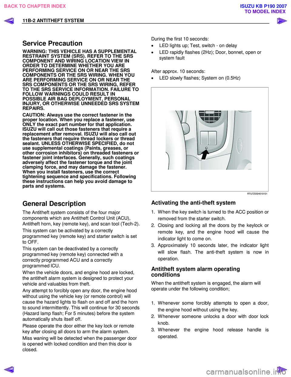
During the first 10 seconds:
• LED lights up; Test, switch - on delay
• LED rapidly flashes (2Hz); Door, bonnet, open or
system fault
After approx. 10 seconds:
• LED slowly flashes; System on (0.5Hz)
RTU7Z0SH019101
Activating the anti-theft system
1. W hen the key switch is turned to the ACC position or
removed from the starter switch.
2. Closing and locking all the doors by the keylock o
r
remote key, and the engine hood will cause the
indicator light to come on.
3. Approximately 10 seconds later, the indicator light will slow flash. The anti-theft system is now in
operation.
Antitheft system alarm operating
conditions
W hen the antitheft system is engaged, the alarm will
operate under the following condition;
1. W henever some forcibly attempts to open a door, the engine hood without using the key.
2. W henever someone unlocks a door with door lock knob.
3. W henever the engine hood release handle is operated.
BACK TO CHAPTER INDEX TO MODEL INDEX
ISUZU KB P190 2007
Page 5989 of 6020

ANTITHEFT SYSTEM 11B-35
Tech-2 Data List
No. Data List Units
1 Battery Voltage V
2 ‘KEY-IN’ Status ON/OFF
3 CDLS-Motor Voltage (Central Door Locking System) V
4 Accident Sensor (Crash Sensor) Active/Inactive
5 Remote Key Active/Inactive
6 Remote-Key Detected Remote Key No.
7 Key Function Detected Lock/Unlock
8 Prev. Detected Remote-Key (Previously) Remote Key No.
9 Previously Key Function Lock/Unlock
10 Remote-Key 1 Status In Range/Not Programmed
11 Remote-Key 2 Status In Range/Not Programmed
12 Remote-Key 3 Status In Range/Not Programmed
13 Remote-Key 4 Status In Range/Not Programmed
14 Remote-Key 5 Status In Range/Not Programmed
15 Front Door Unlock Switch Active/Inactive
16 Front Door Lock Switch Active/Inactive
17 Front Door Lock Status Active/Inactive
18 Auto Door Unlock Switch Active/Inactive
19 Auto Door Lock Switch Active/Inactive
20 Auto Door Lock Status Active/Inactive
21 Trunk Signal Switch *Not used Open/Closed
22 Doorknob Switch Open/Closed
23 Doorknob Status Lock/Unlock
24 Trunk Doorknob Switch *Not used Open/Closed
25 Trunk Doorknob Status *Not used Lock/Unlock
26 Driver Door Switch Open/Closed
27 Driver Door Status Open/Closed
28 All Door Switch Open/Closed
29 All Door Status Open/Closed
30 Door lock Tamper Switches Open/Closed
31 Engine Hood Switch Open/Closed
32 Engine Hood Status Open/Closed
33 Trunk Switch *Not used Open/Closed
34 Trunk Status *Not used Open/Closed
35 Pane Breakage Connected *Not used Yes/No
36 Pane Breakage Status *Not used Disabled/Abled
37 CDLS-Motor Current (Central Door Locking System) A
38 CDLS-Motor Unlock (Central Door Locking System) V
39 CDLS-Motor Lock (Central Door Locking System) V
40 Overflow Protection Active/Inactive
41 Turn Signal Active/Inactive
42 Horn Connected Yes/No
43 Horn Signal Active/Inactive
44 Theft LED ON/OFF
45 CDLS-Status (Central Door Locking System) Lock/Unlock
46 Selftest Request Active/Inactive
47 Last Use —
48 Theft Status Disabled/Abled
49 Alarm Status Active/Inactive
50 Security Wait Time Active/Inactive
BACK TO CHAPTER INDEX
TO MODEL INDEX
ISUZU KB P190 2007