dimensions ISUZU KB P190 2007 Workshop Repair Manual
[x] Cancel search | Manufacturer: ISUZU, Model Year: 2007, Model line: KB P190, Model: ISUZU KB P190 2007Pages: 6020, PDF Size: 70.23 MB
Page 55 of 6020

HEATER AND AIR CONDITIONING 1-21
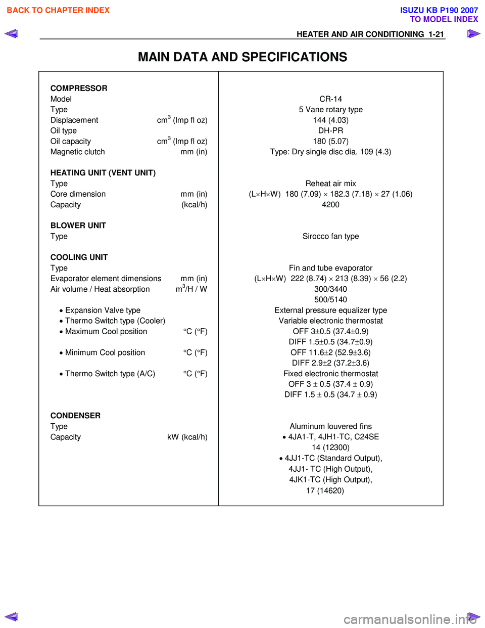
MAIN DATA AND SPECIFICATIONS
COMPRESSOR
Model CR-14
Type 5 Vane rotary type
Displacement cm3 (lmp fl oz) 144 (4.03)
Oil type DH-PR
Oil capacity cm3 (lmp fl oz) 180 (5.07)
Magnetic clutch mm (in) Type: Dry single disc dia. 109 (4.3)
HEATING UNIT (VENT UNIT)
Type Reheat air mix
Core dimension mm (in) (L×H ×W ) 180 (7.09) × 182.3 (7.18) × 27 (1.06)
Capacity (kcal/h) 4200
BLOWER UNIT
Type Sirocco fan type
COOLING UNIT
Type Fin and tube evaporator
Evaporator element dimensions mm (in) (L×H ×W ) 222 (8.74) × 213 (8.39) × 56 (2.2)
Air volume / Heat absorption m3/H / W
300/3440
500/5140
• Expansion Valve type External pressure equalizer type
• Thermo Switch type (Cooler) Variable electronic thermostat
• Maximum Cool position °C ( °F) OFF 3± 0.5 (37.4 ±0.9)
DIFF 1.5 ±0.5 (34.7 ±0.9)
• Minimum Cool position °C ( °F)
OFF 11.6
±2 (52.9 ±3.6)
DIFF 2.9 ±2 (37.2 ±3.6)
• Thermo Switch type (A/C) °C ( °F) Fixed electronic thermostat
OFF 3 ± 0.5 (37.4 ± 0.9)
DIFF 1.5 ± 0.5 (34.7 ± 0.9)
CONDENSER
Type Aluminum louvered fins
Capacity kW (kcal/h) •
4JA1-T, 4JH1-TC, C24SE
14 (12300)
• 4JJ1-TC (Standard Output),
4JJ1- TC (High Output), 4JK1-TC (High Output),
17 (14620)
BACK TO CHAPTER INDEX
TO MODEL INDEX
ISUZU KB P190 2007
Page 155 of 6020

FRAME AND BUMPER 2A-1
SECTION 2A
FRAME AND BUMPER
TABLE OF CONTENTS
Front Bumper (A type) ...................................................................................................... 2A- 2
Front Bumper (B type)....................................................................................................... 2A- 5
Rear Step Bumper ............................................................................................................. 2A - 8
Rear Bumper and Rear Guard .......................................................................................... 2A- 11
Front Air Dam .................................................................................................................. ...2A - 13
Frame Dimensions ............................................................................................................ 2A- 14
PAGE
BACK TO CHAPTER INDEX
TO MODEL INDEX
ISUZU KB P190 2007
Page 168 of 6020

2A-14 FRAME AND BUMPER FRAME DIMENSIONS 4×
××
× 2, LWB, REGULAR CAB MODEL
RTW72AXF000601
BACK TO CHAPTER INDEX
TO MODEL INDEX
ISUZU KB P190 2007
Page 198 of 6020

SHEET METAL 2B-1
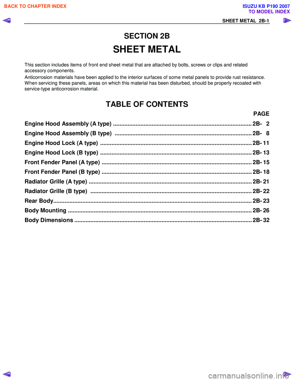
SECTION 2B
SHEET METAL
This section includes items of front end sheet metal that are attached by bolts, screws or clips and related
accessory components.
Anticorrosion materials have been applied to the interior surfaces of some metal panels to provide rust resistance.
W hen servicing these panels, areas on which this material has been disturbed, should be properly recoated with
service-type anticorrosion material.
TABLE OF CONTENTS
PAGE
Engine Hood Assembly (A type) ...................................................................................... 2B- 2
Engine Hood Assembly (B type) ..................................................................................... 2B- 8
Engine Hood Lock (A type) .............................................................................................. 2B- 11
Engine Hood Lock (B type) .............................................................................................. 2B- 13
Front Fender Panel (A type) ............................................................................................. 2B- 15
Front Fender Panel (B type) ............................................................................................. 2B- 18
Radiator Grille (A type) ..................................................................................................... 2 B- 21
Radiator Grille (B type) .................................................................................................... 2B - 22
Rear Body...................................................................................................................... ..... 2B- 23
Body Mounting .................................................................................................................. 2B- 26
Body Dimensions .............................................................................................................. 2B - 32
BACK TO CHAPTER INDEX
TO MODEL INDEX
ISUZU KB P190 2007
Page 229 of 6020

2B-32 SHEET METAL
BODY DIMENSIONS
Service Precaution
RUW 52BSH003301
Note : Be sure to measure from the center of one hole to the
center of the other hole.
BACK TO CHAPTER INDEX
TO MODEL INDEX
ISUZU KB P190 2007
Page 486 of 6020

4B-42 REAR AXLE
425RS063
Reassembly
Adjustment of Clearance between
Friction Disc and Plate
1. Measuring depth of differential case
mm(in)
Standard (A-B) 80.58 (3.17)
(C) 10.58 (0.42)
425RS064
2. Measuring overall length of pressure ring, friction disc and plate assembly
• Assemble pinion shaft with pressure ring, then
friction disc and plate.
• Measure length between plates at both ends
over V-shape groove. (D)
425 RS065
3.
After A, B, C and D dimensions are measured,
perform adjustment with the following procedure.
• Measure spring plate :
1.75 mm (0.069 in) × 4 pcs (E)
• Measure thickness of plate spring
Standard dimension :
1.75 mm (0.069 in) × 2 pcs (F)
4. Select a friction disc or plate so that ((A-B+C) - (D+E) = 0.06 to 0.20 mm (0.002 to 0.008 in.) and
also the difference in total dimension of friction
disc and plate and spring plate (left/right side)
does not exceed 0.05 mm (0.002 in.).
Thickness : 1.65, 1.75, 1.85 mm (0.065, 0.069, 0.073 in)
Adjusting Backlash of Side Gear in
Axial Direction
1. Measuring depth of differential case mm(in)
Standard (F-B) 82.03 (3.23)
(G) 12.03 (0.47)
BACK TO CHAPTER INDEX
TO MODEL INDEX
ISUZU KB P190 2007
Page 2026 of 6020

6A-12 ENGINE MECHANICAL (C24SE)
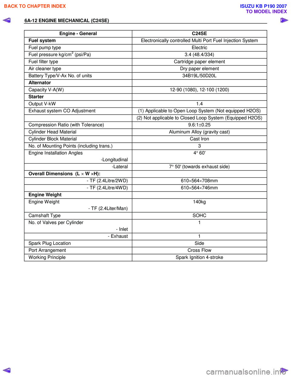
Engine - General C24SE
Fuel system Electronically controlled Multi Port Fuel Injection System
Fuel pump type Electric
Fuel pressure kg/cm2 (psi/Pa) 3.4 (48.4/334)
Fuel filter type Cartridge paper element
Air cleaner type Dry paper element
Battery Type/V-Ax No. of units 34B19L/50D20L
Alternator
Capacity V-A(W ) 12-90 (1080), 12-100 (1200)
Starter
Output V-kW 1.4
Exhaust system CO Adjustment (1) Applicable to Open Loop System (Not equipped H2OS)
(2) Not applicable to Closed Loop System (Equipped H2OS)
Compression Ratio (with Tolerance) 9.6:1±0.25
Cylinder Head Material Aluminum Alloy (gravity cast)
Cylinder Block Material Cast Iron
No. of Mounting Points (including trans.) 3
Engine Installation Angles
-Longitudinal 4
° 60'
-Lateral 7° 50' (towards exhaust side)
Overall Dimensions (L ×
××
×
W ×
××
×
H):
- TF (2.4Litre/2W D)610×564 ×708mm
- TF (2.4Litre/4W D) 610×564 ×746mm
Engine Weight
Engine W eight
- TF (2.4Liter/Man) 140kg
Camshaft Type
SOHC
No. of Valves per Cylinder
- Inlet1
- Exhaust
1
Spark Plug Location Side
Port Arrangement Cross Flow
W orking Principle Spark Ignition 4-stroke
BACK TO CHAPTER INDEX
TO MODEL INDEX
ISUZU KB P190 2007
Page 2090 of 6020

6A-76 ENGINE MECHANICAL (C24SE)
Spark Plug Thread
Recondition
Ream thread and recut using commercially available spark
plug thread drill (observe manufacturer's instructions).
Removal
Remove thread bush on spark plug. (dimensions (A) =
17mm/0.67in.)
Tighten (Torque)
Spark plug with thread bush into cylinder head - 25N ⋅m (2.5
kgf ⋅m) - use.
BACK TO CHAPTER INDEX
TO MODEL INDEX
ISUZU KB P190 2007
Page 2094 of 6020

6A-80 ENGINE MECHANICAL (C24SE)
Cylinder Head (continued)
Valve System
Valve lifter valve play compensator
(hydraulic)
Valve rotators
(inlet or outlet) outlet
Valve play
(warm or cold) inlet mm 0
outlet mm 0
Cylinder head bottom, face parallelism mm 0.05
Valve Dimensions
C24SE
A in mm B in
mm C(diameter in mm) and identification mark D
1) 2) Normal K Oversize K1
0.075 Oversize K2
0.150 Oversize A
0.250
Inlet valve
104.2 103.8 41.8 7.012
6.998 7.087
7.073 7.162
7.148 7.262
7.248 44
°
Outlet valve 104.0 103.6 36.5 6.992
6.978 7.087
7.053 7.142
7.128 7.242
7.228 44
°
Valve stem
bore - 7.050
7.030 7.125
7.105 7.200
7.180 7.300
7.280 -
1) Production
2) Customer service
The P and A department only supplies valves with a length of 103.8mm (inlet valve) and 103.6mm (outlet valve)
only
Camshaft
2.4L
Identification letter K
Colour code Normal size -
0.1mm undersize violet
Radial runout mm 0.03
End play mm 0.09 to 0.21
Cam lift Inlet and outlet valve mm 6.67
BACK TO CHAPTER INDEX
TO MODEL INDEX
ISUZU KB P190 2007
Page 2096 of 6020

6A-82 ENGINE MECHANICAL (C24SE)
Crankshaft, Cylinder Block
Cylinder Grinding and Piston Dimensions
Size Cylinder bore dia. in mm Cylinder to Related piston dia. in mm Piston head
Crankshaft co- efficient
housing
co-efficient
over to over to
Production
(2.4L) 1 87.48
87.49 87.49
87.50 99
00 87.46
87.47 87.47
87.48 99
00
Customer service (2.4L) - 87.99 88.00 0+0.5 87.97 87.98 7+0.5
Piston diameter must be measured at the position "D".
*inclusive
Cylinder Bore
Rebore cylinder Permissible oversize to 0.5mm (see parts
microfiche)
After reboring, invalidate original crankcase
housing coefficient and drive in new oversize
coefficient
Permissible out-of-round: 0.013mm
Permissible taper: 0.013mm
Measure out-of-round in bore at 4 different
heights
Piston projection above upper edge of cylinder block 0.40mm
Piston
Type Recessed pistons
Clearance For short-blocks and cylinder blocks with complete pistons, the clearance is 0.02 to
0.04mm
For replacement (oversize), depending on
available pistons, a clearance of 0.02 to
0.04mm is permissible
BACK TO CHAPTER INDEX
TO MODEL INDEX
ISUZU KB P190 2007