fuse ISUZU KB P190 2007 Workshop Repair Manual
[x] Cancel search | Manufacturer: ISUZU, Model Year: 2007, Model line: KB P190, Model: ISUZU KB P190 2007Pages: 6020, PDF Size: 70.23 MB
Page 5663 of 6020

9A-28 SUPPLEMENTAL RESTRAINT SYSTEM
20. The passenger inflator requires no special
precaution after deployment. 95% of the
particulate emission is potassium chloride (KLC),
which is commonly sold as an edible salt-
substitute. Even if water is applied, post
deployment products are relatively pH neutral.
Disposing of the inflator by burying it in a landfill
will not produce any hazardous products. As with
any dusty environment, safety goggles, dust mask
and gloves should be worn.
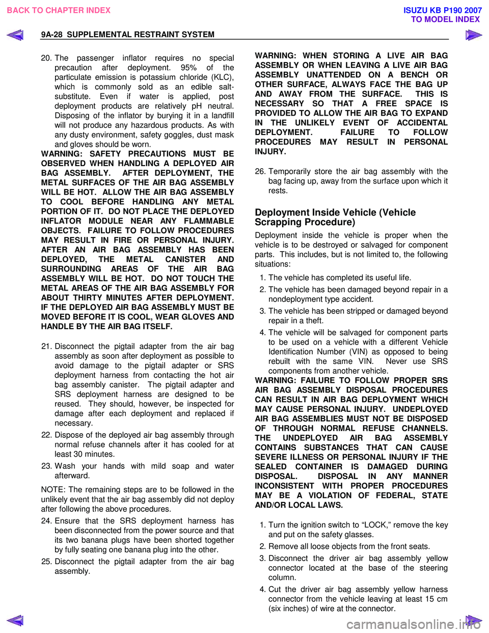
WARNING: SAFETY PRECAUTIONS MUST BE
OBSERVED WHEN HANDLING A DEPLOYED AIR
BAG ASSEMBLY. AFTER DEPLOYMENT, THE
METAL SURFACES OF THE AIR BAG ASSEMBLY
WILL BE HOT. ALLOW THE AIR BAG ASSEMBLY
TO COOL BEFORE HANDLING ANY METAL
PORTION OF IT. DO NOT PLACE THE DEPLOYED
INFLATOR MODULE NEAR ANY FLAMMABLE
OBJECTS. FAILURE TO FOLLOW PROCEDURES
MAY RESULT IN FIRE OR PERSONAL INJURY.
AFTER AN AIR BAG ASSEMBLY HAS BEEN
DEPLOYED, THE METAL CANISTER AND
SURROUNDING AREAS OF THE AIR BAG
ASSEMBLY WILL BE HOT. DO NOT TOUCH THE
METAL AREAS OF THE AIR BAG ASSEMBLY FOR
ABOUT THIRTY MINUTES AFTER DEPLOYMENT.
IF THE DEPLOYED AIR BAG ASSEMBLY MUST BE
MOVED BEFORE IT IS COOL, WEAR GLOVES AND
HANDLE BY THE AIR BAG ITSELF.
21. Disconnect the pigtail adapter from the air bag assembly as soon after deployment as possible to
avoid damage to the pigtail adapter or SRS
deployment harness from contacting the hot ai
r
bag assembly canister. The pigtail adapter and
SRS deployment harness are designed to be
reused. They should, however, be inspected fo
r
damage after each deployment and replaced if
necessary.
22. Dispose of the deployed air bag assembly through normal refuse channels after it has cooled for at
least 30 minutes.
23. W ash your hands with mild soap and wate
r
afterward.
NOTE: The remaining steps are to be followed in the
unlikely event that the air bag assembly did not deplo
y
after following the above procedures.
24. Ensure that the SRS deployment harness has been disconnected from the power source and that
its two banana plugs have been shorted togethe
r
by fully seating one banana plug into the other.
25. Disconnect the pigtail adapter from the air bag assembly.
WARNING: WHEN STORING A LIVE AIR BAG
ASSEMBLY OR WHEN LEAVING A LIVE AIR BAG
ASSEMBLY UNATTENDED ON A BENCH OR
OTHER SURFACE, ALWAYS FACE THE BAG UP
AND AWAY FROM THE SURFACE. THIS IS
NECESSARY SO THAT A FREE SPACE IS
PROVIDED TO ALLOW THE AIR BAG TO EXPAND
IN THE UNLIKELY EVENT OF
ACCIDENTAL
DEPLOYMENT. FAILURE TO FOLLOW
PROCEDURES MAY RESULT IN PERSONAL
INJURY.
26. Temporarily store the air bag assembly with the bag facing up, away from the surface upon which it
rests.
Deployment Inside Vehicle (Vehicle
Scrapping Procedure)
Deployment inside the vehicle is proper when the
vehicle is to be destroyed or salvaged for component
parts. This includes, but is not limited to, the following
situations:
1. The vehicle has completed its useful life.
2. The vehicle has been damaged beyond repair in a nondeployment type accident.
3. The vehicle has been stripped or damaged beyond repair in a theft.
4. The vehicle will be salvaged for component parts to be used on a vehicle with a different Vehicle
Identification Number (VIN) as opposed to being
rebuilt with the same VIN. Never use SRS
components from another vehicle.
WARNING: FAILURE TO FOLLOW PROPER SRS
AIR BAG ASSEMBLY DISPOSAL PROCEDURES
CAN RESULT IN AIR BAG DEPLOYMENT WHICH
MAY CAUSE PERSONAL INJURY. UNDEPLOYED
AIR BAG ASSEMBLIES MUST NOT BE DISPOSED
OF THROUGH NORMAL REFUSE CHANNELS.
THE UNDEPLOYED AIR BAG ASSEMBLY
CONTAINS SUBSTANCES THAT CAN CAUSE
SEVERE ILLNESS OR PERSONAL INJURY IF THE
SEALED CONTAINER IS DAMAGED DURING
DISPOSAL. DISPOSAL IN ANY MANNER
INCONSISTENT WITH PROPER PROCEDURES
MAY BE A VIOLATION OF FEDERAL, STATE
AND/OR LOCAL LAWS.
1. Turn the ignition switch to “LOCK,” remove the ke
y
and put on the safety glasses.
2. Remove all loose objects from the front seats.
3. Disconnect the driver air bag assembly yello
w
connector located at the base of the steering
column.
4. Cut the driver air bag assembly yellow harness connector from the vehicle leaving at least 15 cm
(six inches) of wire at the connector.
BACK TO CHAPTER INDEX TO MODEL INDEXISUZU KB P190 2007
Page 5667 of 6020

9A-32 SUPPLEMENTAL RESTRAINT SYSTEM
Service Precautions for SRS
Component Service
CAUTION: When fasteners are removed, always
reinstall them at the same location from which
they were removed. If a fastener needs to be
replaced, use the correct part number fastener fo
r
that application. If the correct part number
fastener is not available, a fastener of equal size
and strength (or stronger) may be used. Fasteners
that are not reused, and those requiring a thread
locking compound will be called out. The correct
torque value must be used when installing
fasteners that require it. If the above conditions
are not followed, parts or system damage could
result.
WARNING: WHEN PERFORMING SERVICE ON OR
AROUND SRS COMPONENTS OR SRS WIRING,
FOLLOW THE PROCEDURES LISTED BELOW TO
TEMPORARILY DISABLE THE SRS. FAILURE TO
FOLLOW PROCEDURES COULD RESULT IN
POSSIBLE AIR BAG DEPLOYMENT, PERSONAL
INJURY OR OTHERWISE UNNEEDED SRS
REPAIRS.
The SRS control unit in the Driver–Passenger SRS
can maintain sufficient voltage to cause a deployment
for up to 15 seconds after the ignition switch is turned
“OFF,” the battery is disconnected, or the fuse
powering the SRS control unit is removed.
Many of the service procedures require removal of the
“SRS” fuse, and disconnection of the air bag assembl
y
from the deployment loop to avoid an accidental
deployment. If the air bag assembly is disconnected
from the deployment loop as noted in the “Disabling
the SRS” procedure that follows, service can begin
immediately without waiting for the 15 second time
period to expire.
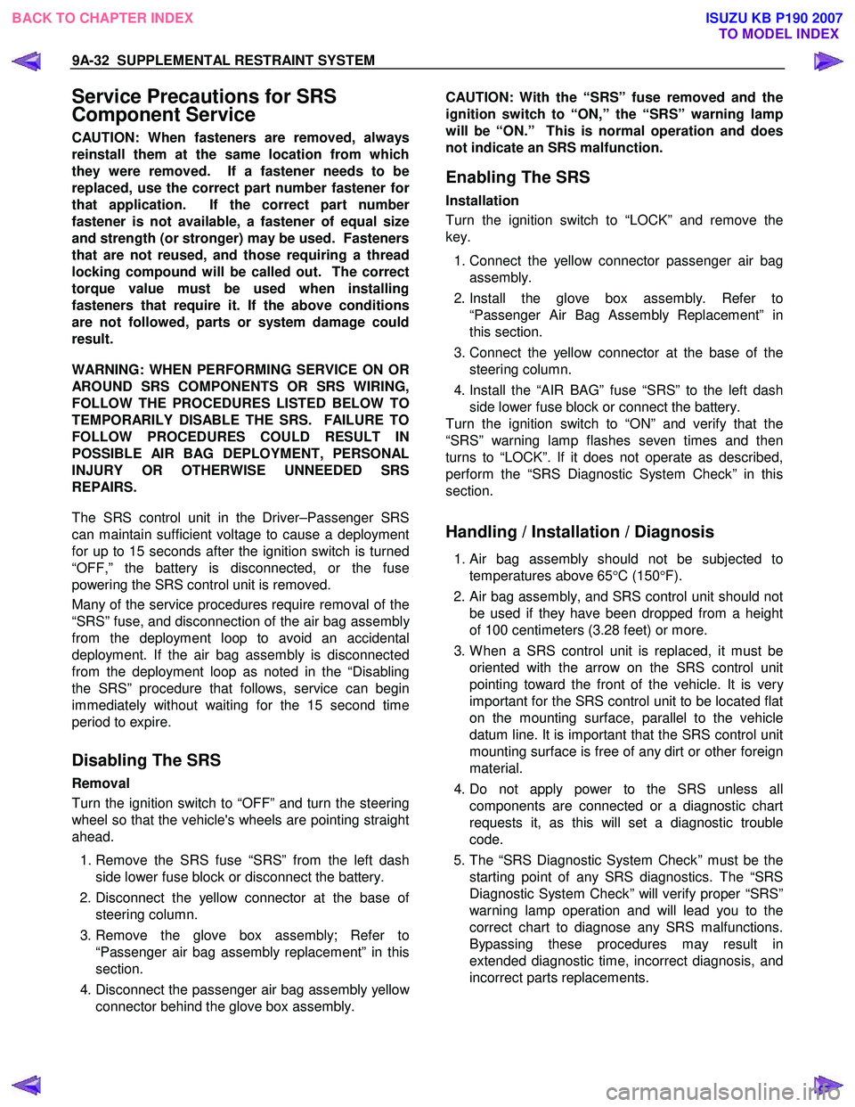
Disabling The SRS
Removal
Turn the ignition switch to “OFF” and turn the steering
wheel so that the vehicle's wheels are pointing straight
ahead.
1. Remove the SRS fuse “SRS” from the left dash side lower fuse block or disconnect the battery.
2. Disconnect the yellow connector at the base o
f
steering column.
3. Remove the glove box assembly; Refer to “Passenger air bag assembly replacement” in this
section.
4. Disconnect the passenger air bag assembly yello
w
connector behind the glove box assembly.
CAUTION: With the “SRS” fuse removed and the
ignition switch to “ON,” the “SRS” warning lamp
will be “ON.” This is normal operation and does
not indicate an SRS malfunction.
Enabling The SRS
Installation
Turn the ignition switch to “LOCK” and remove the
key.
1. Connect the yellow connector passenger air bag assembly.
2. Install the glove box assembly. Refer to “Passenger Air Bag Assembly Replacement” in
this section.
3. Connect the yellow connector at the base of the steering column.
4. Install the “AIR BAG” fuse “SRS” to the left dash side lower fuse block or connect the battery.
Turn the ignition switch to “ON” and verify that the
“SRS” warning lamp flashes seven times and then
turns to “LOCK”. If it does not operate as described,
perform the “SRS Diagnostic System Check” in this
section.
Handling / Installation / Diagnosis
1. Air bag assembly should not be subjected to
temperatures above 65 °C (150 °F).
2.
Air bag assembly, and SRS control unit should not
be used if they have been dropped from a height
of 100 centimeters (3.28 feet) or more.
3. W hen a SRS control unit is replaced, it must be oriented with the arrow on the SRS control unit
pointing toward the front of the vehicle. It is ver
y
important for the SRS control unit to be located flat
on the mounting surface, parallel to the vehicle
datum line. It is important that the SRS control unit
mounting surface is free of any dirt or other foreign
material.
4. Do not apply power to the SRS unless all components are connected or a diagnostic chart
requests it, as this will set a diagnostic trouble
code.
5. The “SRS Diagnostic System Check” must be the starting point of any SRS diagnostics. The “SRS
Diagnostic System Check” will verify proper “SRS”
warning lamp operation and will lead you to the
correct chart to diagnose any SRS malfunctions.
Bypassing these procedures may result in
extended diagnostic time, incorrect diagnosis, and
incorrect parts replacements.
BACK TO CHAPTER INDEX TO MODEL INDEXISUZU KB P190 2007
Page 5690 of 6020

9A1-8 RESTRAINT CONTROL SYSTEM
Circuit Description
W hen the ignition switch is first turned “ON”, “Ignition 1”
voltage is applied from the “SRS” fuse to the SRS
control unit at the “Ignition 1” input terminals “1”. The
SRS control unit responds by flashing the “SRS”
warning lamp seven times, while performing tests on
the SRS.
Notes On System Check Chart
1. The “SRS” warning lamp should flash seven times after the ignition is first turned “ON”.
2.
After the “SRS” warning lamp flashes seven times, it
should turn to “LOCK”
3. This test checks for the proper operation of the “Serial Data” line. This test will also determine
whether history diagnostic trouble codes are stored
and, if so, identify them.
4. Improper operation of the “SRS” warning lamp is indicated. This test differentiates between ‘a
warning lamp stays “ON” condition’ and ‘a warning
lamp does not come “ON” condition’.
5. This test checks for proper operation of the “Serial Data” line. This test will also identify the stored
diagnostic trouble codes and whether they are
current or history.
Diagnostic Aids
The order in which diagnostic trouble codes are
diagnosed is very important. Failure to diagnose the
diagnostic trouble codes in the order specified ma
y
result in extended diagnostic time, incorrect diagnosis
and incorrect parts replacement.
SRS Diagnostic System Check
Step Action Yes No
1 Note the “SRS” warning lamp as the ignition switch is turned
“ON”.
Does the “SRS” warning lamp flash seven (7) times? Go to Step 2 Go to Step 3
2 Note the “SRS” warning lamp after it flashed 7 times.
Does the “SRS” warning lamp go “OFF”? Go to Step 4 Go to Step 5
3 Note the “SRS” warning lamp as the ignition switch is turned
“ON”.
Does the “SRS” warning lamp come “ON” steady? Go to Chart B. Go to Chart C.
4
1. Note the “SRS” warning lamp as the ignition switch is turned
“ON”.
Ignition switch is at “LOCK”.
2. Connect a scan tool to data link connector.
3. Follow direction given in the scan tool instruction manual.
Ignition switch is “ON”.
4. Request the SRS diagnostic trouble code display, recode all
history diagnostic trouble code(s), specifying as current or
history in repair order.
Is (are) diagnostic trouble code(s) displayed?
Ignition switch
“LOCK”.
W hen DTC B0071 is set, go to DTC B0071 Chart.
For all other history codes refer to
“Diagnostic Aids” For that specific DTC.
A history DTC indicates the
malfunction has
been repaired or is intermittent. SRS is functional
and free of
malfunctions, no
further diagnosis is required.
If scan tool
indicated “NO DATA
RECEIVED,” refer to chassis
electrical section 8.
BACK TO CHAPTER INDEX TO MODEL INDEX
ISUZU KB P190 2007
Page 5694 of 6020

9A1-12 RESTRAINT CONTROL SYSTEM
Chart B “SRS” Warning Lamp Comes “ON” Steady
RTW 79ALF000301
Circuit Description
W hen the ignition switch is first turned “ON”, “Ignition 1”
voltage is applied from the “METER” fuse to the “SRS”,
warning lamp which is connected to “SRS W arning
Lamp”, terminal “4”. The “SRS” fuses apply system
voltage to the “Ignition 1” inputs, terminals “1”. The
SRS control unit responds by flashing the “SRS”
warning lamp 7 times. If “Ignition 1” is less than 9 volts,
the “SRS” warning lamp will come “ON” solid with no
DTCs set.
Chart Test Description
Number(s) below refer to step number(s) on the
diagnostic chart:
2. This test checks for an open in the “Ignition 1” circuit to the SRS control unit.
3. This test checks for the voltage of “Ignition 1”.
4. This test determines whether the malfunction is a short to ground in the SRS warning lamp circuit.
BACK TO CHAPTER INDEX TO MODEL INDEX
ISUZU KB P190 2007
Page 5696 of 6020

9A1-14 RESTRAINT CONTROL SYSTEM
Chart C “SRS” Warning Lamp Does Not Come “ON” Steady
RTW 79ALF000301
Circuit Description
W hen the ignition switch is first turned “ON”, “Ignition 1”
voltage is applied from the “METER” fuse to the “SRS”
warning lamp which is connected to the “SRS W arning
Lamp”, terminal “4”. The “SRS” fuse applies system
voltage to the “Ignition 1” inputs, terminals “35”. The
SRS control unit responds by flashing the “SRS”
warning lamp seven times. If “Ignition 1” is more than
16 volts, the “SRS” warning lamp will still be “OFF” solid
with no DTCs set.
Chart Test Description
Number(s) below refer to step number(s) on the
diagnostic chart:
1. This test decides whether power is available to the
SRS control unit warning lamp power feed circuit.
2. This test determines whether the voltage is present
in the warning lamp circuit.
3. This test determines if the malfunction is in the
instrument cluster.
4. This test checks for open in the warning lamp
circuitry.
5. This test isolates the SRS warning lamp circuit and
checks for a short in the SRS warning lamp circuit to
B+.
8. This test checks for a short from the SRS control
unit warning lamp power feed circuit to ground.
9. This test determines whether the short to ground is
due to a short in the wiring.
BACK TO CHAPTER INDEX TO MODEL INDEX
ISUZU KB P190 2007
Page 5697 of 6020

RESTRAINT CONTROL SYSTEM 9A1-15
Chart C “SRS” Warning Lamp Does Not Come “ON” Steady
Step Action Yes No
1
1. W hen measurements are requested in this chart, use a 5-
8840-0366-0DMM with a correct terminal adapter from 5-
8840-0385-0.
2. Ignition switch is at “LOCK”.
3. Remove and inspect the “METER” fuse to the “SRS” warning lamp.
Is the fuse good? Go to Step 2 Go to Step 7
2
1. Ignition switch is at “LOCK”.
2. Disconnect the SRS coil and passenger air bag assembly
yellow connector which is located at the base of the steering
column and behind the glove box assembly.
3. Disconnect the SRS control unit.
4. Ignition switch is “ON”.
5. Measure the voltage on the SRS control unit harness connector from the terminal “4” to terminal “3” (ground).
Is system voltage present on terminal “4”? Go to Step 4 Go to Step 3
3
1. Ignition switch is at “LOCK”.
2. Remove instrument meter cluster.
3. Check for proper connection to instrument cluster at the SRS warning lamp circuit terminal.
4. If ok, then remove and inspect the “AIR BAG” bulb.
Is the bulb good? Go to Step 5 Replace bulb.
Go to Step 6
4
1. Ignition switch is at “LOCK”.
2. Disconnect instrument meter cluster harness connector.
3. Ignition switch is “ON”.
4. Measure the voltage on the SRS control unit harness
connector from terminal “4” to terminal “3” (ground).
Is the voltage 1 volt or less? Go to Chart A Replace SRS
harness.
Go to Step 6
5
1. Install the bulb.
2. Measure the resistance from the instrument meter cluster
harness connector SRS warning lamp circuit terminal to the
SRS control unit harness connector terminal “4”.
Is the resistance 5.0 ohms or less? Service instrument
meter cluster.
Install instrument meter cluster. Go to Step 6 Replace SRS
harness.
Go to Step 6
6 Reconnect all SRS components and ensure all components are
properly mounted.
Is this step finished? Repeat the “SRS
Diagnostic System Check” Go to Step 6
7
Perform chart C.
Is this step finished? Go to Step 8 Go to Step 1
8
1. Replace the “METER” fuse.
2. Ignition switch is “ON”. W ait 10 Seconds then ignition switch
is at “LOCK”.
3. Remove and inspect the “METER” fuse.
Is the fuse good? Install “METER”
fuse.
Go to Step 10 Go to Step 9
BACK TO CHAPTER INDEX
TO MODEL INDEX
ISUZU KB P190 2007
Page 5698 of 6020

9A1-16 RESTRAINT CONTROL SYSTEM
Step Action Yes No
9
1. Disconnect the SRS coil and the passenger air bag assembly
yellow connectors located at the base of the steering column
and behind the glove box assembly.
2. Disconnect the SRS control unit.
3. Replace the “METER” fuse.
4. Ignition switch is “ON”-wait 10 seconds.
5. Ignition switch is at “LOCK”.
6. Remove and inspect the “METER” fuse.
Is the fuse good? Install “METER”
fuse.
Go to Chart A Replace SRS
harness.
Replace “METER” fuse.
Go to Step 10
10 Reconnect all the SRS components and ensure all the
components are properly mounted.
Is this step finished? Repeat the “SRS
Diagnostic System Check” —
BACK TO CHAPTER INDEX
TO MODEL INDEX
ISUZU KB P190 2007
Page 5750 of 6020

9A1-68 RESTRAINT CONTROL SYSTEM
DTC B0061 (Flash Code 61) Warning Lamp Circuit Failure
RTW 79ALF000301
Circuit Description
W hen the ignition switch is first turned “ON”, “Ignition 1”
voltage is applied from the “METER” fuse to the “SRS”
warning lamp which is connected to “SRS" warning
lamp, terminal “4”. The “SRS” fuse applies system
voltage to the “Ignition 1” inputs, terminal “1”. The SRS
control unit responds by flashing the “SRS” warning
lamp 7 times. The SRS control unit monitors the “SRS
W arning Lamp" terminal "4" for conditions that are
incorrect for the commanded state of the "SRS" warning
lamp.
For example, a failure condition exists if the SRS
control unit detects low voltage when the "SRS" warning
lamp is commanded OFF, or high voltage when the
"SRS" warning lamp is commanded ON. If the SRS
control unit detects an improper voltage on the “SRS
W arning Lamp" terminal "4", DTC B0061 will set.
DTC Will Set When
The SRS control unit try to turn "ON" the "SRS" warning
lamp but the battery voltage is not supplied to terminal
"4".
The SRS control unit try to turn "OFF" the "SRS"
warning lamp but the battery voltage is supplied to
terminal "4".
Action Taken
If circuits of the “SRS" warning lamp power supply and
ground are normal condition, the SRS control unit turns
“ON” the “SRS” warning lamp and sets a diagnostic
trouble code.
BACK TO CHAPTER INDEX TO MODEL INDEX
ISUZU KB P190 2007
Page 5751 of 6020

RESTRAINT CONTROL SYSTEM 9A1-69
DTC Will Clear When
The malfunction is no longer occurring and the ignition
is turned to “LOCK”.
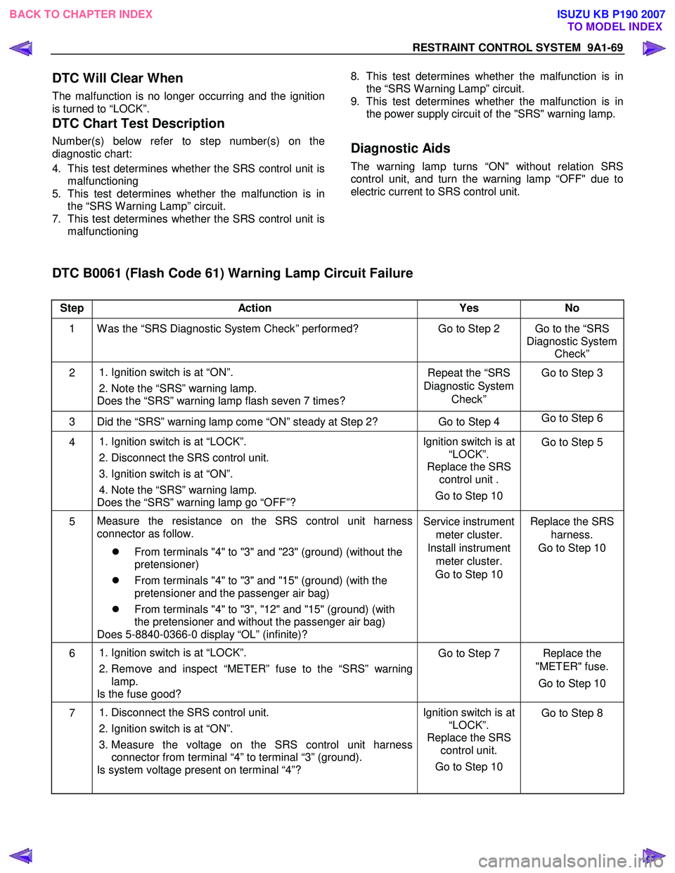
DTC Chart Test Description
Number(s) below refer to step number(s) on the
diagnostic chart:
4. This test determines whether the SRS control unit is malfunctioning
5. This test determines whether the malfunction is in the “SRS W arning Lamp” circuit.
7. This test determines whether the SRS control unit is malfunctioning
8. This test determines whether the malfunction is in
the “SRS W arning Lamp” circuit.
9. This test determines whether the malfunction is in the power supply circuit of the "SRS" warning lamp.
Diagnostic Aids
The warning lamp turns “ON" without relation SRS
control unit, and turn the warning lamp “OFF" due to
electric current to SRS control unit.
DTC B0061 (Flash Code 61) Warning Lamp Circuit Failure
Step Action Yes No
1 W as the “SRS Diagnostic System Check” performed? Go to Step 2 Go to the “SRS
Diagnostic System Check”
2
1. Ignition switch is at “ON”.
2. Note the “SRS” warning lamp.
Does the “SRS” warning lamp flash seven 7 times? Repeat the “SRS
Diagnostic System Check” Go to Step 3
3 Did the “SRS” warning lamp come “ON” steady at Step 2? Go to Step 4
Go to Step 6
4
1. Ignition switch is at “LOCK”.
2. Disconnect the SRS control unit.
3. Ignition switch is at “ON”.
4. Note the “SRS” warning lamp.
Does the “SRS” warning lamp go “OFF”? Ignition switch is at
“LOCK”.
Replace the SRS control unit .
Go to Step 10 Go to Step 5
5
Measure the resistance on the SRS control unit harness
connector as follow.
�z From terminals "4" to "3" and "23" (ground) (without the
pretensioner)
�z From terminals "4" to "3" and "15" (ground) (with the
pretensioner and the passenger air bag)
�z From terminals "4" to "3", "12" and "15" (ground) (with
the pretensioner and without the passenger air bag)
Does 5-8840-0366-0 display “OL” (infinite)? Service instrument
meter cluster.
Install instrument meter cluster.
Go to Step 10 Replace the SRS
harness.
Go to Step 10
6
1. Ignition switch is at “LOCK”.
2. Remove and inspect “METER” fuse to the “SRS” warning lamp.
Is the fuse good? Go to Step 7 Replace the
"METER" fuse.
Go to Step 10
7 1. Disconnect the SRS control unit.
2. Ignition switch is at “ON”.
3. Measure the voltage on the SRS control unit harness connector from terminal “4” to terminal “3” (ground).
Is system voltage present on terminal “4”? Ignition switch is at
“LOCK”.
Replace the SRS control unit.
Go to Step 10
Go to Step 8
BACK TO CHAPTER INDEX
TO MODEL INDEX
ISUZU KB P190 2007
Page 5752 of 6020

9A1-70 RESTRAINT CONTROL SYSTEM
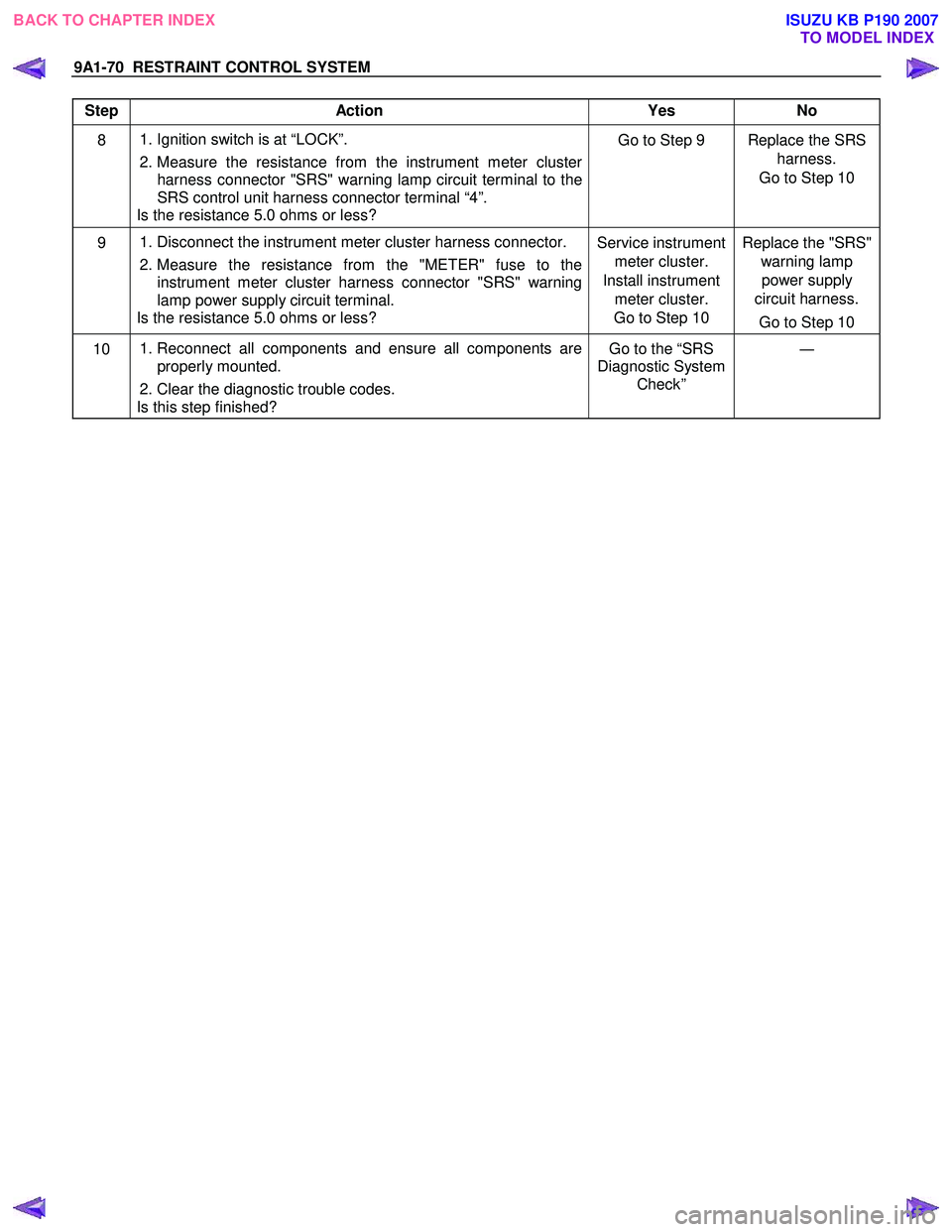
Step Action Yes No
8 1. Ignition switch is at “LOCK”.
2. Measure the resistance from the instrument meter cluster harness connector "SRS" warning lamp circuit terminal to the
SRS control unit harness connector terminal “4”.
Is the resistance 5.0 ohms or less? Go to Step 9 Replace the SRS
harness.
Go to Step 10
9 1. Disconnect the instrument meter cluster harness connector.
2. Measure the resistance from the "METER" fuse to the instrument meter cluster harness connector "SRS" warning
lamp power supply circuit terminal.
Is the resistance 5.0 ohms or less? Service instrument
meter cluster.
Install instrument meter cluster.
Go to Step 10 Replace the "SRS"
warning lamp power supply
circuit harness.
Go to Step 10
10 1. Reconnect all components and ensure all components are
properly mounted.
2. Clear the diagnostic trouble codes.
Is this step finished? Go to the “SRS
Diagnostic System Check” ―
BACK TO CHAPTER INDEX
TO MODEL INDEX
ISUZU KB P190 2007