fuse ISUZU KB P190 2007 Workshop Repair Manual
[x] Cancel search | Manufacturer: ISUZU, Model Year: 2007, Model line: KB P190, Model: ISUZU KB P190 2007Pages: 6020, PDF Size: 70.23 MB
Page 5561 of 6020

ELECTRICAL-BODY AND CHASSIS 8A-623
No. Connector face No. Connector face
E89
White
Immobilizer engine control unit E107
MAP sensor
E90
Black
ECM J1 E108
Blue Cylinder revolution
E92
Silver
Fuse & relay box E109
Blue SPGA
E94
~
E95 NOT USED E110
Brown
Backup light switch
E96
Black
Reverse switch E111
BrownNeutral switch
E97
~
E98 NOT USED E112
Gray
1st switch
E99
Black
O2 sensor-RH E113
Gray Clutch sleave cylinder
E100
Black
O2 sensor-LH E114
~
E115 NOT USED
E101
~
E105 NOT USED E116
Backup light switch
E106
EVRV: Turbo
BACK TO CHAPTER INDEX
TO MODEL INDEXISUZU KB P190 2007
Page 5568 of 6020

8A-630 ELECTRICAL-BODY AND CHASSIS
No. Connector face No. Connector face
P1
Silver
Battery (+) P9
(4JA1T- (L))
SilverACG (B)
P2
Silver
Relay & Fuse box P9
(4JH1-TC)
Silver
ACG (B)
P3
Black
Starter (S) P10
SilverEngine ground
P4
(HFV6)
Silver
Starter (B) P11
SilverFuse & relay box
P4
Silver
Starter (B) P12
NOT USED
P5
Silver
Battery (-) P13
Gray Shift on the fly actuator
P6
Silver
Body earth (Ground) P14
NOT USED
P7
Battery (ALT) P15
Silver2nd battery (+)
P8
Green
ACG (L)
P9
(HFV6)
Silver
ACG (B)
BACK TO CHAPTER INDEX
TO MODEL INDEXISUZU KB P190 2007
Page 5593 of 6020

Cruise Control – HFV6 Page 8C–15
Step Action Yes No
3 Check the ignition supply circuits to the Stop Lamp Switch assembly
connector C – 44 pin 1 is serviceable using a multimeter set to
measure voltage, refer to 2.3 W iring Diagrams in this Section
Is there a +12 volt signal present at connector C – 44 pin 1?
Go to Step 4 Replace the faulty
fusible link Main,
IG2 or Stop Light fuse (refer to Note 1).
If either of the
fusible links or fuse blows again, repair
or replace the faulty circuit (refer to
Note 1)
4 1 Connect Tech 2 to the DLC.
2 On Tech 2 select: Body / Powertrain Interface Module / Diagnostic Data
Display.
3 Scroll to Cruise Main Switch.
4 W hile monitoring Tech 2, press the cruise control switch ON– OFF button.
Does Tech 2 display the following:
• Inactive and Active as the cruise control switch is pressed?
Go to Step 5 Go to Step 11
5 1 Scroll to Cruise Resume Switch.
2 While monitoring Tech 2, rotate the cruise control switch.
Does Tech 2 display the following:
• Inactive when the cruise control switch is in the neutral
position?
• Res / Acc when the cruise control switch is rotated to the RES–
ACC. Position? Go to Step 6 Go to Step 12
6
1 Scroll to Cruise Set Switch.
2 W hile monitoring Tech 2, press the cruise control switch.
Does Tech 2 display the following:
• Inactive when the cruise control switch is in the neutral
position?
• Set / Coast when the cruise control switch is pressed to the
SET–COAST position? Go to Step 7 Go to Step 13
7 1 Scroll to Cruise Cancel Switch.
2 While monitoring Tech 2, rotate the cruise control switch.
Does Tech 2 display the following:
• Inactive when the cruise control switch is in the neutral
position?
• Cancel when the cruise control switch is rotated to the CANCEL
position? Go to Step 8 Go to Step 14
BACK TO CHAPTER INDEX
TO MODEL INDEXISUZU KB P190 2007
Page 5596 of 6020

Cruise Control – HFV6 Page 8C–18
Step Action Yes No
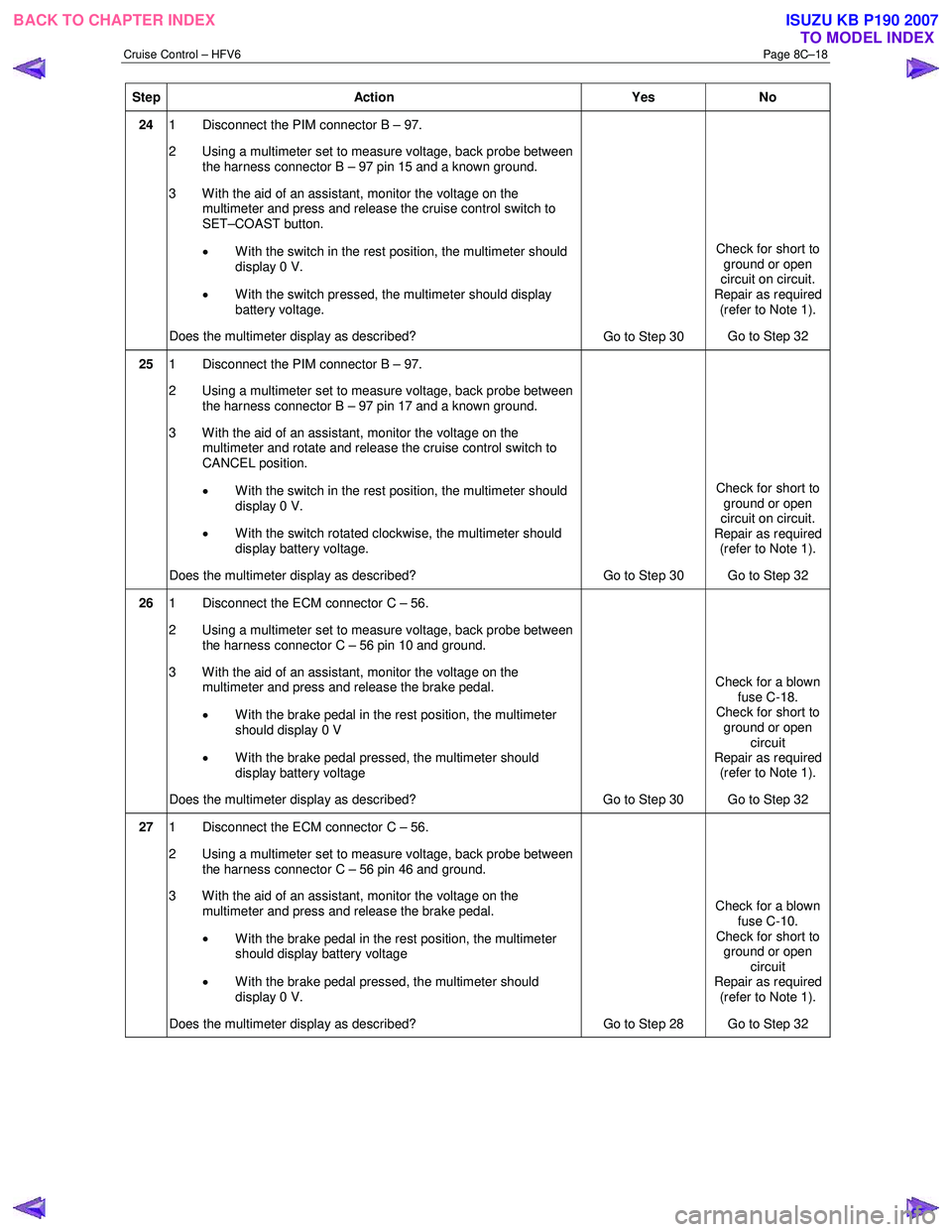
24 1 Disconnect the PIM connector B – 97.
2 Using a multimeter set to measure voltage, back probe between the harness connector B – 97 pin 15 and a known ground.
3 With the aid of an assistant, monitor the voltage on the multimeter and press and release the cruise control switch to
SET–COAST button.
• With the switch in the rest position, the multimeter should
display 0 V.
• With the switch pressed, the multimeter should display
battery voltage.
Does the multimeter display as described? Go to Step 30 Check for short to
ground or open
circuit on circuit.
Repair as required (refer to Note 1).
Go to Step 32
25 1 Disconnect the PIM connector B – 97.
2 Using a multimeter set to measure voltage, back probe between the harness connector B – 97 pin 17 and a known ground.
3 W ith the aid of an assistant, monitor the voltage on the multimeter and rotate and release the cruise control switch to
CANCEL position.
• With the switch in the rest position, the multimeter should
display 0 V.
• W ith the switch rotated clockwise, the multimeter should
display battery voltage.
Does the multimeter display as described? Go to Step 30 Check for short to
ground or open
circuit on circuit.
Repair as required (refer to Note 1).
Go to Step 32
26 1 Disconnect the ECM connector C – 56.
2 Using a multimeter set to measure voltage, back probe between the harness connector C – 56 pin 10 and ground.
3 With the aid of an assistant, monitor the voltage on the multimeter and press and release the brake pedal.
• W ith the brake pedal in the rest position, the multimeter
should display 0 V
• W ith the brake pedal pressed, the multimeter should
display battery voltage
Does the multimeter display as described? Go to Step 30 Check for a blown
fuse C-18.
Check for short to
ground or open circuit
Repair as required (refer to Note 1).
Go to Step 32
27 1 Disconnect the ECM connector C – 56.
2 Using a multimeter set to measure voltage, back probe between the harness connector C – 56 pin 46 and ground.
3 With the aid of an assistant, monitor the voltage on the multimeter and press and release the brake pedal.
• W ith the brake pedal in the rest position, the multimeter
should display battery voltage
• W ith the brake pedal pressed, the multimeter should
display 0 V.
Does the multimeter display as described? Go to Step 28 Check for a blown
fuse C-10.
Check for short to ground or open
circuit
Repair as required (refer to Note 1).
Go to Step 32
BACK TO CHAPTER INDEX TO MODEL INDEXISUZU KB P190 2007
Page 5597 of 6020

Cruise Control – HFV6 Page 8C–19
Step Action Yes No
28 1 Disconnect the ECM connector C – 56.
2 Using a multimeter set to measure voltage, back probe between the harness connector C – 56 pin 53 and ground.
3 W ith the aid of an assistant, monitor the voltage on the multimeter and press and release the clutch pedal.
• With the clutch pedal in the rest position, the multimeter
should display battery voltage
• W ith the clutch pedal pressed, the multimeter should
display 0 V
Does the multimeter display as described? Go to Step 31 Check for a blown
fuse C-4.
Check for short to ground or open circuit
Repair as required (refer to Note 2).
Go to Step 32
29 Check all associated circuits and connectors for the following:
• Loose or damaged connections
• Intermittent faults.
Refer to the Wiring Diagrams in this Section and repair as required.
W as the repair completed? Go to Step 32 —
30 Replace the PIM, refer to 6E1 Powertrain Interface Module – V6.
W as the repair completed? Go to Step 32 —
31 Replace the ECM module, refer to 6C1-3 Engine Management – V6
Service Operations.
W as the repair completed? Go to Step 32 —
32 Operate the system in order to verify the repair.
Did you correct the condition? System OK Go to Step 1
When all diagnosis and repairs are completed, clear all DTCs and check the system for correct operation.
BACK TO CHAPTER INDEX
TO MODEL INDEXISUZU KB P190 2007
Page 5628 of 6020

ACCESSORIES 9-23
No. Connector face No. Connector face
D-22
White
Tweeter -LH P-1
SilverBattery (+)
H-14
White
Rear body ∼ Rear door -LH P-2
SilverRelay & Fuse box
H-16
White
Rear body ∼ Rear door -RH P-5
SilverBattery (-)
H-18
White
Engine room ∼ INST P-6
SilverBody earth
H-36
White
INST ~ Front door-RH P-10
SilverEngine ground
H-37
White
INST ~ Front door-LH R-7
BlackRear speaker -LH
H-39
White
INST ~ Front door-LH R-8
BlackRear speaker -RH
H-42
White
INST ~ Front door-driver
H-43
INST ~ Body
H-43
White
INST ~ Body
BACK TO CHAPTER INDEX TO MODEL INDEXISUZU KB P190 2007
Page 5656 of 6020

SUPPLEMENTAL RESTRAINT SYSTEM 9A-21
On–Vehicle Service
Service Precaution
WARNING: WHEN PERFORMING SERVICE ON OR
AROUND SRS COMPONENTS OR SRS WIRING,
FOLLOW THE PROCEDURES LISTED BELOW TO
TEMPORARILY DISABLE THE SRS. FAILURE TO
FOLLOW PROCEDURES COULD RESULT IN
POSSIBLE AIR BAG DEPLOYMENT, PERSONAL
INJURY OR OTHERWISE UNNECESSARY SRS
REPAIRS.
The SRS control unit in Driver–Passenger SRS can
maintain sufficient voltage to cause a deployment fo
r
up to 15 seconds after the ignition switch is turned
“OFF,” the battery is disconnected, or the fuse
powering the SRS control unit is removed.
Many of the service procedures require removal of the
“SRS” fuse, and disconnection of the air bag assembl
y
from the deployment loop to avoid an accidental
deployment. If the air bag assembly is disconnected
from the deployment loop as noted in the “Disabling
the SRS” procedure that follows, service can begin
immediately without waiting for the 15 second time
period to expire.
Disabling The SRS
Removal
Turn the ignition switch to “LOCK” and remove the
key.
1. Remove the SRS fuse “SRS”, from the side of the driver’s side of the instrument panel fuse block o
r
disconnect the battery.
2. Disconnect the yellow connector at the base of the steering column.
3. Remove the glove box assembly, refer to “Passenger Air Bag Assembly Replacement” in
this manual.
4. Disconnect the yellow connector behind the glove box assembly.
CAUTION: With the “SRS” fuse removed and
ignition switched “ON”, the “SRS” warning lamp
will be “ON”. This is normal operation and does
not indicate an SRS malfunction.
Enabling The SRS
Installation
CAUTION: Never use the air bag assembly from
another vehicle or different model year air bag
assembly.
Use only a new air bag assembly matched to the
TFR/S which is being repaired.
Turn the ignition switch to “LOCK” and remove the
key.
1. Connect the yellow connector passenger air bag assembly.
2. Install the glove box assembly. Refer to “Passenger air bag assembly replacement” in this
manual.
3. Connect the yellow connector at the base of the steering column.
4. Install the “AIR BAG” fuse “SRS” to the side of the driver’s side of the instrument panel fuse block o
r
connect the battery.
Turn the ignition switch to “ON” and verify that the
“SRS” warning lamp flashes seven times and then
turns to “LOCK”. If it does not operate as described,
perform the “SRS Diagnostic System Check” in this
manual.
Handling / Installation / Diagnosis
1. The air bag assembly should not be subjected to temperatures above 65
°C (150°F).
2. The air bag assembly, and SRS control unit, should not be used if they have been dropped from
a height of 100 centimeters (3.28 feet) or more.
3. W hen the SRS control unit is replaced, it must be oriented with the arrow on the sensor pointing
toward the front of the vehicle. It is very important
for the SRS control unit to be located flat on the
mounting surface, parallel to the vehicle datum
line. It is important that the SRS control unit
mounting surface is free of any dirt or other foreign
material.
4. Do not apply power to the SRS unless all components are connected or a diagnostic chart
requests it, as this will set a diagnostic trouble
code.
5. The “SRS Diagnostic System Check” must be the starting point of any SRS diagnostics. The “SRS
Diagnostic System Check” will verify proper “SRS”
warning lamp operation and will lead you to the
correct chart to diagnose any SRS malfunctions.
Bypassing these procedures may result in
extended diagnostic time, incorrect diagnosis, and
incorrect parts replacement.
BACK TO CHAPTER INDEX TO MODEL INDEXISUZU KB P190 2007
Page 5658 of 6020

SUPPLEMENTAL RESTRAINT SYSTEM 9A-23
Air Bag Assembly Scrapping Procedure
During the course of a vehicle's useful life, certain
situations may arise which will necessitate the disposal
of a live (undeployed) air bag assembly. This
information covers proper procedures for disposing o
f
a live air bag assembly.
Before a live air bag assembly can be disposed of, it
must be deployed.
A live air bag assembly must not
be disposed of through normal refuse channels.
WARNING: FAILURE TO FOLLOW PROPER
SUPPLEMENTAL RESTRAINT SYSTEM (SRS) AIR
BAG ASSEMBLY DISPOSAL PROCEDURES CAN
RESULT IN AIR BAG DEPLOYMENT WHICH MAY
CAUSE PERSONAL INJURY. AN UNDEPLOYED
AIR BAG ASSEMBLY MUST NOT BE DISPOSED
OF THROUGH NORMAL REFUSE CHANNELS.
THE UNDEPLOYED AIR BAG ASSEMBLY
CONTAINS SUBSTANCES THAT CAN CAUSE
SEVERE ILLNESS OR PERSONAL INJURY IF THE
SEALED CONTAINER IS DAMAGED DURING
DISPOSAL. DISPOSAL IN ANY MANNER
INCONSISTENT WITH PROPER PROCEDURES
MAY BE A VIOLATION OF FEDERAL, STATE, AND
/
OR LOCAL LAW.
In situations which require deployment of a live air bag
assembly, deployment may be accomplished inside o
r
outside the vehicle. The method employed depends
upon the final disposition of the particular vehicle, as
noted in “Deployment Outside Vehicle” and
“Deployment Inside Vehicle” in this section.
Deployment Outside Vehicle (Driver Air
Bag Assembly)
Deployment outside the vehicle is proper when the
vehicle is to be returned to service. This includes, fo
r
example, situations in which the vehicle will be
returned to useful service after a functionally o
r
cosmetically deficient air bag assembly is replaced.
Deployment and disposal of a malfunctioning air bag
assembly is, of course, subject to any required
retention period.
For deployment of a live (undeployed) air bag
assembly outside the vehicle, the deployment
procedure must be followed exactly. Always wea
r
safety glasses during this deployment procedure until
a deployed air bag assembly is scrapped or until an
undeployed air bag assembly is shipped. Before
performing the procedures you should be familiar with
servicing the SRS and with proper handling of the ai
r
bag assembly. Procedures should be read fully before
they are performed.
The following procedure requires use of a 5-8840-
2468-06 SRS deployment harness with appropriate
pigtail adapter. Do not attempt the procedure without
a 5-8840-2468-0 adapter.
WARNING: F
AILURE TO FOLLOW PROCEDURES
IN THE ORDER LISTED MAY RESULT IN
PERSONAL INJURY. NEVER CONNECT THE
DEPLOYMENT HARNESS TO ANY POWER
SOURCE BEFORE CONNECTING THE
DEPLOYMENT HARNESS TO THE DRIVER AIR
BAG ASSEMBLY. DEPLOYMENT HARNESS
SHALL REMAIN SHORTED AND NOT BE
CONNECTED TO A POWER SOURCE UNTIL THE
AIR BAG IS TO BE DEPLOYED. THE AIR BAG
ASSEMBLY WILL IMMEDIATELY DEPLOY THE AIR
BAG WHEN A POWER SOURCE IS CONNECTED
TO IT. WEAR SAFETY GLASSES THROUGHOUT
THIS ENTIRE DEPLOYMENT AND DISPOSAL
PROCEDURE.
NOTE: This information applies only to driver air bag
assembly. Refer to “Deployment Outside Vehicle
(Passenger Air Bag assembly)” in this section fo
r
information on passenger air bag assembly scrapping.
1. Turn the ignition switch to “LOCK”, remove the ke
y
and put on safety glasses.
2. Inspect the 5-8840-2468-0 SRS Deployment Harness and appropriate pigtail adapter fo
r
damage. If the harness or pigtail adapter is
damaged, discard and obtain a replacement.
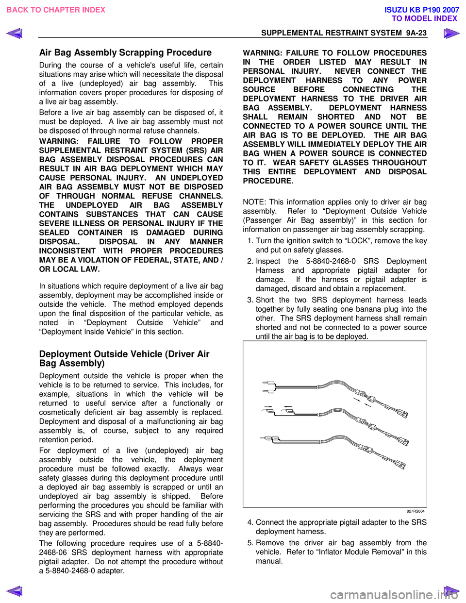
3. Short the two SRS deployment harness leads together by fully seating one banana plug into the
other. The SRS deployment harness shall remain
shorted and not be connected to a power source
until the air bag is to be deployed.
827RS004
4. Connect the appropriate pigtail adapter to the SRS deployment harness.
5. Remove the driver air bag assembly from the vehicle. Refer to “Inflator Module Removal” in this
manual.
BACK TO CHAPTER INDEX TO MODEL INDEXISUZU KB P190 2007
Page 5660 of 6020

SUPPLEMENTAL RESTRAINT SYSTEM 9A-25
NOTE: W hen the air bag deploys, the driver air bag
assembly may jump about 30 cm (one foot) vertically.
This is a normal reaction of the driver air bag to the
force of the rapid gas expansion inside the air bag.
NOTE: W hen the air bag deploys, the rapid gas
expansion will create a substantial noise. Notify all
people in the immediate area that you intend to deplo
y
the driver air bag.
WARNING: THE DEPLOYMENT HARNESS SHALL
REMAIN SHORTED AND NOT BE CONNECTED TO
A POWER SOURCE UNTIL THE AIR BAG IS TO BE
DEPLOYED. THE AIR BAG ASSEMBLY WILL
IMMEDIATELY DEPLOY THE AIR BAG WHEN
A
POWER SOURCE IS CONNECTED TO IT.
CONNECTING THE DEPLOYMENT HARNESS TO
THE POWER SOURCE SHOULD ALWAYS BE THE
LAST STEP IN THE AIR BAG ASSEMBLY
DEPLOYMENT PROCEDURE. FAILURE TO
FOLLOW PROCEDURES IN THE ORDER LISTED
MAY RESULT IN PERSONAL INJURY.
16. Connect the SRS deployment harness wires to the power source to immediately deploy the driver ai
r
bag. Recommended application: 12 volts
minimum, 2 amps minimum. A vehicle battery is
suggested.
17. Disconnect the SRS deployment harness from the power source.
18. Short the two SRS deployment harness leads together by fully seating one banana plug into the
other.
19. In the unlikely event that the driver air bag assembly did not deploy after following these
procedures, proceed immediately with Steps 24
through 26. If 19. the driver air bag assembly did
deploy, proceed with Steps 20 through 23.
20. Put on a pair of shop gloves and safety glasses to protect your hands and eyes from possible
irritation and heat when handling the deployed
driver air bag assembly. After the air bag assembl
y
has been deployed, the surface of the air bag may
contain a powdery residue. This power consists
primarily of cornstarch (used to lubricate the bag
as it inflates) and by-products of the chemical
reaction. Sodium hydroxide dust (similar to lye
soap) is produced as a by-product of the
deployment reaction. The sodium hydroxide then
quickly reacts with the atmospheric moisture and
is converted to sodium carbonate and sodium
bicarbonate (baking soda). Therefore, it is unlikel
y
that sodium hydroxide will be present after
deployment.
WARNING: SAFETY PRECAUTIONS MUST BE
OBSERVED WHEN HANDING A DEPLOYED AIR
BAG ASSEMBLY. AFTER DEPLOYMENT, THE
METAL SURFACES OF THE AIR BAG ASSEMBLY
WILL BE VERY HOT. ALLOW THE INFLATOR
MODULE TO COOL BEFORE HANDLING ANY
METAL PORTION OF IT. DO NOT PLACE THE
DEPLOYED AIR BAG ASSEMBLY NEAR ANY
FLAMMABLE OBJECTS. FAILURE TO FOLLOW
PROCEDURES MAY RESULT IN FIRE OR
PERSONAL INJURY.
AFTER A DRIVER AIR BAG ASSEMBLY HAS BEEN
DEPLOYED, THE METAL CANISTER AND
SURROUNDING AREAS OF THE DRIVER AIR BAG
ASSEMBLY WILL BE VERY HOT. DO NOT TOUCH
THE METAL AREAS OF THE DRIVER AIR BAG
ASSEMBLY FOR ABOUT TEN MINUTES AFTER
DEPLOYMENT. IF THE DEPLOYED DRIVER AIR
BAG ASSEMBLY MUST BE MOVED BEFORE IT IS
COOL, WEAR GLOVES AND HANDLE BY THE AIR
BAG OR TRIM COVER.
21. Disconnect the pigtail adapter from the driver ai
r
bag assembly as soon after deployment as
possible. This will prevent damage to the pigtail
adapter or SRS deployment harness due to
possible contact with the hot driver air bag
assembly canister. The pigtail adapter can be
reused. They should, however, be inspected fo
r
damage after each deployment and replaced i
f
necessary.
22. Dispose of the deployed driver air bag assembl
y
through normal refuse channels after it has cooled
for at least 30 minutes.
23. W ash your hands with mild soap and wate
r
afterward.
NOTE: The remaining steps are to be followed in the
unlikely event that the driver air bag assembly did not
deploy after following these procedures.
24. Ensure that the SRS deployment harness has been disconnected from the power source and that
its two banana plugs have been shorted togethe
r
by fully seating one banana plug into the other.
25. Disconnect the pigtail adapter from the driver ai
r
bag assembly.
WARNING: WHEN STORING A LIVE AIR BAG
ASSEMBLY OR WHEN LEAVING A LIVE
INFLATOR MODULE UNATTENDED ON A BENCH
OR OTHER SURFACE, ALWAYS FACE THE BAG
AND TRIM COVER UP AND AWAY FROM THE
SURFACE. THIS IS NECESSARY SO THAT A FREE
SPACE IS PROVIDED TO ALLOW THE AIR BAG TO
EXPAND IN THE UNLIKELY EVENT OF
ACCIDENTAL DEPLOYMENT. FAILURE TO
FOLLOW PROCEDURES MAY RESULT IN
PERSONAL INJURY.
BACK TO CHAPTER INDEX TO MODEL INDEXISUZU KB P190 2007
Page 5661 of 6020

9A-26 SUPPLEMENTAL RESTRAINT SYSTEM
26. Temporarily store the driver air bag assembly with
its trim cover facing up, away from the surface
upon which it rests.
Deployment Outside Vehicle (Passenger
Air Bag Assembly)
WARNING: FAILURE TO FOLLOW PROPER SRS
AIR BAG ASSEMBLY DISPOSAL PROCEDURES
CAN RESULT IN AIR BAG DEPLOYMENT WHICH
MAY CAUSE PERSONAL INJURY. UNDEPLOYED
AIR BAG ASSEMBLIES MUST NOT BE DISPOSED
OF THROUGH NORMAL REFUSE CHANNELS.
THE UNDEPLOYED AIR BAG ASSEMBLY
CONTAINS SUBSTANCES THAT CAN CAUSE
SEVERE ILLNESS OR PERSONAL INJURY IF THE
SEALED CONTAINER IS DAMAGED DURING
DISPOSAL. DISPOSAL IN ANY MANNER
INCONSISTENT WITH PROPER PROCEDURES
MAY BE A VIOLATION OF FEDERAL, STATE
AND/OR LOCAL LAWS.
Deployment out of the vehicle is proper when the
vehicle is to be returned to service. This includes, fo
r
example, situations in which a functionally or
cosmetically deficient air bag assembly is replaced.
Deployment and disposal of an air bag assembly is, o
f
course, subject to any required retention period.
For deployment of a live air bag assembly out of the
vehicle, the deployment procedure must be followed
exactly. Always wear safety glasses during this
deployment procedure until the deployed air bag
assembly is scrapped. Before performing the
procedures, you should be familiar with servicing the
SRS system and with proper handling of the air bag
assembly. Procedures should be read fully before
they are performed.
The following procedure requires use of a 5-8840-
2468-0 SRS Deployment Harness with the appropriate
pigtail adapter. The procedure also requires the use
of a 5-8840-2420-0 Passenger Side SRS Module
Deployment Fixture. Do not attempt this procedure
without a 5-8840-2468-0 and adapter, and a 5-8840-
2420-0.
WARNING: FAILURE TO FOLLOW PROCEDURES
IN THE ORDER LISTED MA
Y RESULT IN
PERSONAL INJURY. NEVER CONNECT THE
DEPLOYMENT HARNESS TO ANY POWER
SOURCE BEFORE CONNECTING THE
DEPLOYMENT HARNESS TO THE AIR BAG
ASSEMBLY. THE DEPLOYMENT HARNESS SHALL
REMAIN SHORTED AND NOT BE CONNECTED TO
A POWER SOURCE UNTIL THE AIR BAG IS TO BE
DEPLOYED. THE AIR BAG ASSEMBLY WILL
IMMEDIATELY DEPLOY THE AIR BAG WHEN
A
POWER SOURCE IS CONNECTED TO IT. WEAR
SAFETY GLASSES THROUGHOUT THIS ENTIRE
DEPLOYMENT AND DISPOSAL PROCEDURE.
NOTE: This information applies only to passenger ai
r
bag assembly. Information for disposing of a live
driver air bag assembly can be found in “Deployment
Outside Vehicle” (Driver Air Bag Assembly) in this
section.
1. Turn the ignition switch to “LOCK”, remove the key, and put on the safety glasses.
2. Inspect the 5-8840-2468-0 SRS Deployment Harness and appropriate pigtail adapter fo
r
damage. If the harness or pigtail is damaged,
discard and obtain a replacement.
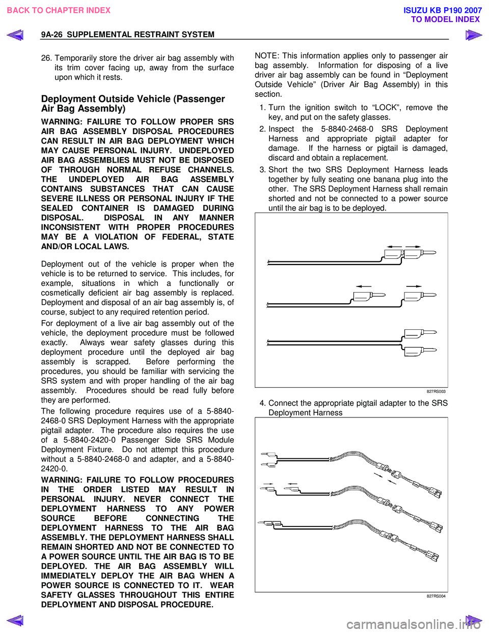
3. Short the two SRS Deployment Harness leads together by fully seating one banana plug into the
other. The SRS Deployment Harness shall remain
shorted and not be connected to a power source
until the air bag is to be deployed.
827RS003
4. Connect the appropriate pigtail adapter to the SRS Deployment Harness
827RS004
BACK TO CHAPTER INDEX TO MODEL INDEXISUZU KB P190 2007