check engine ISUZU KB P190 2007 Workshop Service Manual
[x] Cancel search | Manufacturer: ISUZU, Model Year: 2007, Model line: KB P190, Model: ISUZU KB P190 2007Pages: 6020, PDF Size: 70.23 MB
Page 724 of 6020
BRAKES 5C-25
Filling Master Cylinder Reservoir
CAUTION:
Use only specified brake fluid. Do not use any fluid which
contains a petroleum base. Do not use a container which
has been used for petroleum based fluids or a containe
r
which is wet with water. Petroleum based fluid will cause
swelling and distortion of rubber parts in the hydraulic
brake system. Water mixed with brake fluid lowers the
fluid boiling point. Keep all fluid containers capped to
prevent contamination.
Always fill the master cylinder reservoir when the engine
is cold.
Never allow the brake fluid to come in contact with the
painted surfaces.
The master cylinder reservoir must be kept properly filled
to ensure adequate reserve and to prevent air and
moisture from entering the hydraulic system. However,
because of expansion due to heat absorbed from the
brakes and the engine, the reservoir must not be
overfilled. Thoroughly clean reservoir cap before removal
to avoid getting dirt into reservoir. Add fluid as required to
bring level to the “MAX” mark on the reservoir tank. Use
“DOT 3” Hydraulic Brake Fluid.
Leakage of Brake Fluid
W ith engine idling, set shift lever in the neutral position and
continue to depress brake pedal at a constant pedal
application force.
Should the pedal stroke become deeper gradually, leakage
from the hydraulic pressure system is possible.
Make sure by visual check that there is no leak.
BLEEDING OF THE BRAKE HYDRAULIC
CIRCUIT
If air enters the bake lines, it will cause poor brake action.
Therefore, bleeding should be performed if the brakes have
been used with the level of brake fluid in the reservoi
r
excessively low or if brake pipes have been disconnected in
the course of brake servicing.
The bleeding operation calls for co-operative action of 2
persons.
• Set the parking brake firmly while bleeding.
• Perform bleeding operation with ENGINE RUNNING, to
prevent damage to push rod seal.
Make sure exhaust is suitably ventilated.
• Bleed the hydraulic system with the fluid reservoir filled to
the specified level.
• Bleed the system starting with the rear wheel cylinde
r
farthest from the master cylinder.
BACK TO CHAPTER INDEX
TO MODEL INDEX
ISUZU KB P190 2007
Page 725 of 6020
5C-26 BRAKES
A bleeding operation is necessary to remove air from the
hydraulic brake system whenever air is introduced into the
hydraulic system. It may be necessary to bleed the hydraulic
system at all four brakes if air has been introduced through a
low fluid level or by disconnecting brake pipes at the maste
r
cylinder. If a brake pipe is disconnected at one wheel, only that
wheel cylinder/caliper needs to be bled. If the pipes are
disconnected at any fitting located between the master cylinde
r
and brakes, then the brake system served by the disconnected
pipe must be bled.
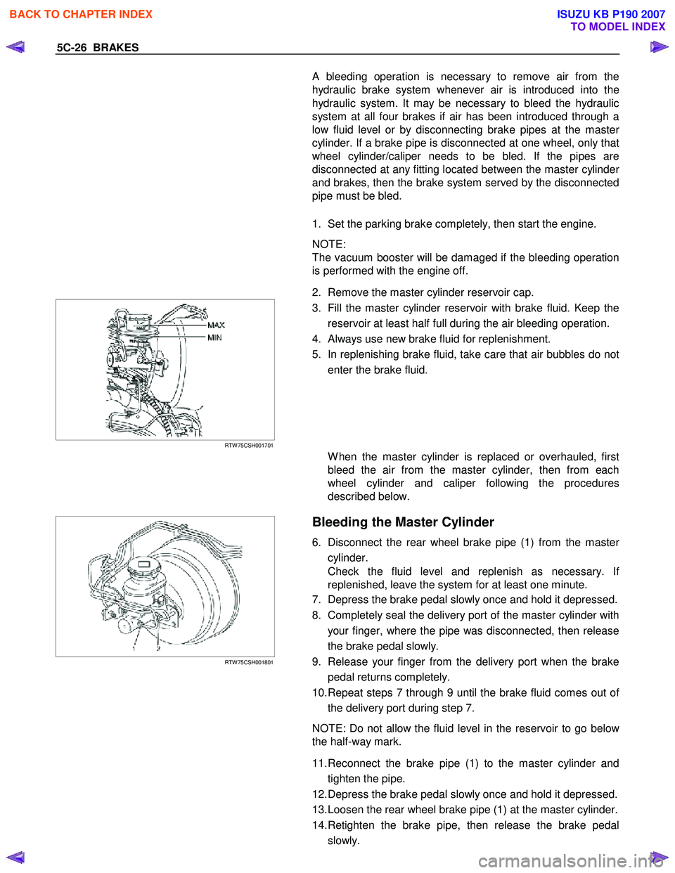
1. Set the parking brake completely, then start the engine.
NOTE:
The vacuum booster will be damaged if the bleeding operation
is performed with the engine off.
2. Remove the master cylinder reservoir cap.
RTW 75CSH001701
3. Fill the master cylinder reservoir with brake fluid. Keep the
reservoir at least half full during the air bleeding operation.
4. Always use new brake fluid for replenishment.
5. In replenishing brake fluid, take care that air bubbles do not enter the brake fluid.
W hen the master cylinder is replaced or overhauled, first
bleed the air from the master cylinder, then from each
wheel cylinder and caliper following the procedures
described below.
RTW 75CSH001801
Bleeding the Master Cylinder
6. Disconnect the rear wheel brake pipe (1) from the master
cylinder.
Check the fluid level and replenish as necessary. I
f
replenished, leave the system for at least one minute.
7. Depress the brake pedal slowly once and hold it depressed.
8. Completely seal the delivery port of the master cylinder with your finger, where the pipe was disconnected, then release
the brake pedal slowly.
9. Release your finger from the delivery port when the brake pedal returns completely.
10. Repeat steps 7 through 9 until the brake fluid comes out o
f
the delivery port during step 7.
NOTE: Do not allow the fluid level in the reservoir to go belo
w
the half-way mark.
11. Reconnect the brake pipe (1) to the master cylinder and tighten the pipe.
12. Depress the brake pedal slowly once and hold it depressed.
13. Loosen the rear wheel brake pipe (1) at the master cylinder.
14. Retighten the brake pipe, then release the brake pedal slowly.
BACK TO CHAPTER INDEX
TO MODEL INDEX
ISUZU KB P190 2007
Page 727 of 6020
5C-28 BRAKES
27. After the bleeding operation is completed on each individual
wheel, check the level of the brake fluid in the reservoir and
replenish up to the “MAX" level as necessary.
28. Attach the reservoir cap.
29. Stop the engine.
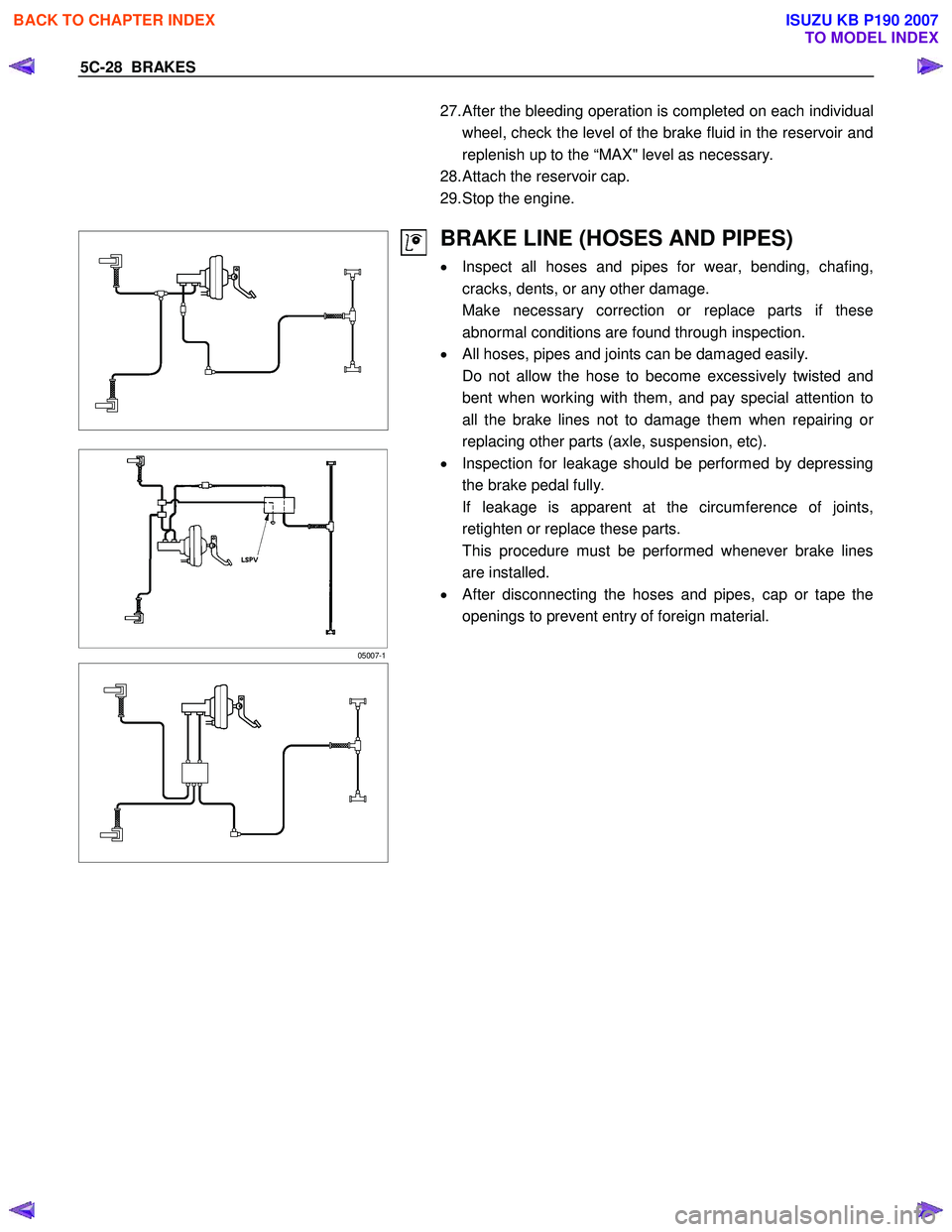
05007-1
BRAKE LINE (HOSES AND PIPES)
• Inspect all hoses and pipes for wear, bending, chafing,
cracks, dents, or any other damage.
Make necessary correction or replace parts if these abnormal conditions are found through inspection.
• All hoses, pipes and joints can be damaged easily.
Do not allow the hose to become excessively twisted and bent when working with them, and pay special attention to
all the brake lines not to damage them when repairing o
r
replacing other parts (axle, suspension, etc).
• Inspection for leakage should be performed by depressing
the brake pedal fully.
If leakage is apparent at the circumference of joints, retighten or replace these parts.
This procedure must be performed whenever brake lines are installed.
• After disconnecting the hoses and pipes, cap or tape the
openings to prevent entry of foreign material.
BACK TO CHAPTER INDEX
TO MODEL INDEX
ISUZU KB P190 2007
Page 760 of 6020

BRAKES 5C-61
RTW 75CSH002701
Important Operation-Removal
1. Brake pipe
W hen hurdling, be careful not to spill brake fluid over the
painted surfaces, as damage to the paint finish will result.
2. Master Cylinder Fixing Nut
3. Bracket
4. Master Cylinder Assembly
NOTE:
W hen removing the master cylinder from the vacuum booster,
be sure to get rid of the internal negative pressure of the
vacuum booster (by, for instance, disconnecting the vacuum
hose) in advance.
If any negative pressure remains in the vacuum booster, the
piston may possibly come out when the master cylinder is
being removed, letting the brake fluid run out.
W hile removing the master cylinder, do not hold the piston as it
can be easily pulled out.
Inspection and Repair
Vacuum Hose (The built in check valve)
360R300002
1) Inspect the check valve, which is installed inside the
vacuum hose.
2) Blow air into the hose from the booster side as shown in the illustration. The air should pass freely through the
hose.
3) Blow air into the hose from the engine side. The check valve should close to block the passage of air.
The vacuum hose and built-in check valve must be
replaced as a set if either is found to be defective.
Important Operation-Installation
10. Vacuum Booster Assembly
Note:
•
Adjustment of push rod of vacuum booster is not carried
out. W hen vacuum booster is damaged it exchanges for a
new article. (Push rod is adjusted)
• Measurement of primary piston position by the side o
f
master cylinder is unnecessary.
9. Spacer
8. Gasket
7. Vacuum Booster Fixing Nut
6. Snap Pin
Install the vacuum booster assembly to the dash panel and
pedal mounting bracket.
BACK TO CHAPTER INDEX
TO MODEL INDEX
ISUZU KB P190 2007
Page 761 of 6020

5C-62 BRAKES
360r300003
5. Vacuum Hose
The check valve (2) is built-in to the vacuum hose.
W hen installing the vacuum hose make sure that the arrow on
the hose is facing the engine (1).
Note:
• Do not apply oil to the vacuum hose.
• Installation direction is very important. The booster will not
operate if the vacuum hose is installed in the wrong
direction.
BACK TO CHAPTER INDEX
TO MODEL INDEX
ISUZU KB P190 2007
Page 787 of 6020
6 – 2 TROUBLESHOOTING
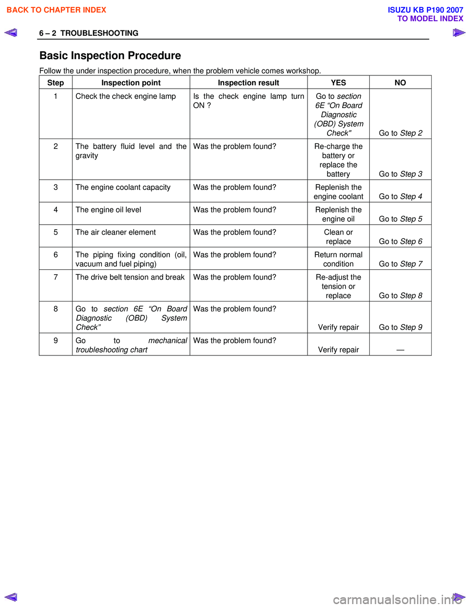
Basic Inspection Procedure
Follow the under inspection procedure, when the problem vehicle comes workshop. Step Inspection point Inspection result YES NO
1 Check the check engine lamp Is the check engine lamp turn ON ? Go to
section
6E “On Board Diagnostic
(OBD) System Check" Go to Step 2
2 The battery fluid level and the
gravity Was the problem found? Re-charge the
battery or
replace the battery Go to Step 3
3 The engine coolant capacity Was the problem found? Replenish the
engine coolant Go to Step 4
4 The engine oil level Was the problem found? Replenish the
engine oil Go to Step 5
5 The air cleaner element Was the problem found? Clean or
replace Go to Step 6
6 The piping fixing condition (oil,
vacuum and fuel piping) Was the problem found? Return normal
condition Go to Step 7
7 The drive belt tension and break Was the problem found? Re-adjust the
tension or replace Go to Step 8
8 Go to section 6E “On Board
Diagnostic (OBD) System
Check” Was the problem found?
Verify repair Go to Step 9
9 Go to mechanical
troubleshooting chart Was the problem found?
Verify repair —
BACK TO CHAPTER INDEX
TO MODEL INDEX
ISUZU KB P190 2007
Page 788 of 6020
TROUBLESHOOTING 6 – 3
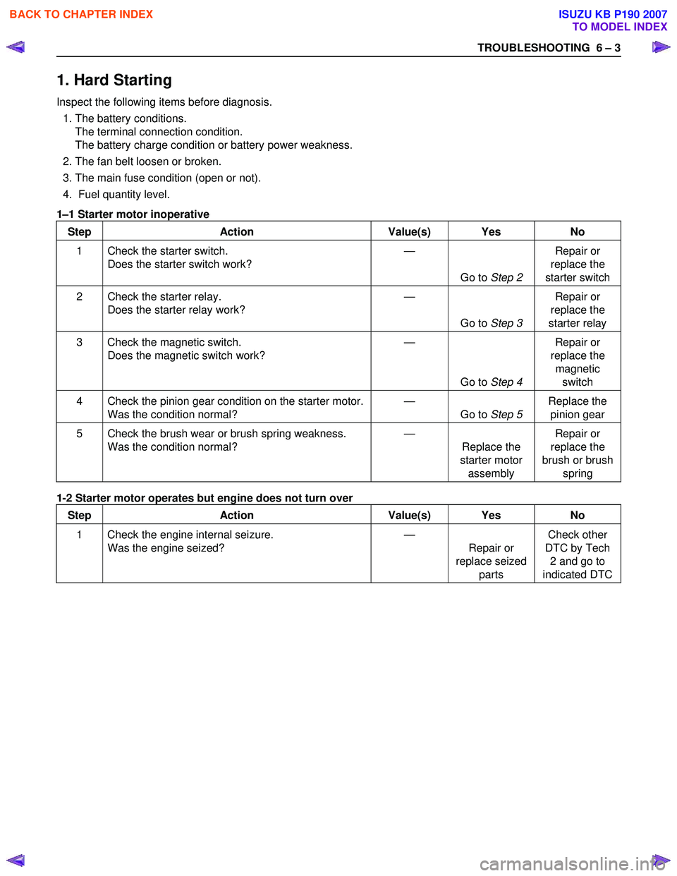
1. Hard Starting
Inspect the following items before diagnosis.
1. The battery conditions. The terminal connection condition.
The battery charge condition or battery power weakness.
2. The fan belt loosen or broken.
3. The main fuse condition (open or not).
4. Fuel quantity level.
1 –1 Starter motor inoperative
Step Action Value(s) Yes No
1 Check the starter switch. Does the starter switch work? —
Go to Step 2 Repair or
replace the
starter switch
2 Check the starter relay. Does the starter relay work? —
Go to Step 3 Repair or
replace the
starter relay
3 Check the magnetic switch. Does the magnetic switch work? —
Go to Step 4 Repair or
replace the magnetic switch
4 Check the pinion gear condition on the starter motor. Was the condition normal? —
Go to Step 5 Replace the
pinion gear
5 Check the brush wear or brush spring weakness. Was the condition normal? —
Replace the
starter motor assembly Repair or
replace the
brush or brush spring
1-2 Starter motor operates but engine does not turn over
Step Action Value(s) Yes No
1 Check the engine internal seizure. Was the engine seized? —
Repair or
replace seized parts Check other
DTC by Tech 2 and go to
indicated DTC
BACK TO CHAPTER INDEX
TO MODEL INDEX
ISUZU KB P190 2007
Page 789 of 6020
6 – 4 TROUBLESHOOTING
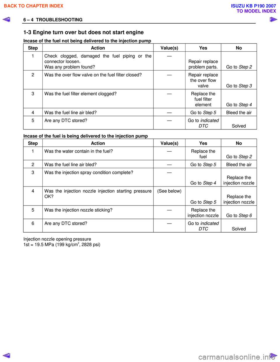
1-3 Engine turn over but does not start engine
Incase of the fuel not being delivered to the injection pump
Step Action Value(s) Yes No
1 Check clogged, damaged the fuel piping or the
connector loosen.
Was any problem found? —
Repair replace problem parts. Go to Step 2
2 Was the over flow valve on the fuel filter closed? — Repair replace
the over flow valve Go to Step 3
3 Was the fuel filter element clogged? — Replace the
fuel filter element Go to Step 4
4 Was the fuel line air bled? — Go to Step 5 Bleed the air
5 Are any DTC stored? — Go to indicated
DTC Solved
Incase of the fuel is being delivered to the injection pump
Step Action Value(s) Yes No
1 Was the water contain in the fuel? — Replace the
fuel Go to Step 2
2 Was the fuel line air bled? — Go to Step 5 Bleed the air
3 Was the injection spray condition complete? —
Go to Step 4 Replace the
injection nozzle
4 Was the injection nozzle injection starting pressure OK? (See below)
Go to Step 5 Replace the
injection nozzle
5 Was the injection nozzle sticking? — Replace the
injection nozzle Go to Step 6
6 Are any DTC stored? — Go to indicated
DTC Solved
Injection nozzle opening pressure
1st = 19.5 MPa (199 kg/cm2, 2828 psi)
BACK TO CHAPTER INDEX
TO MODEL INDEX
ISUZU KB P190 2007
Page 803 of 6020
6 – 18 TROUBLESHOOTING
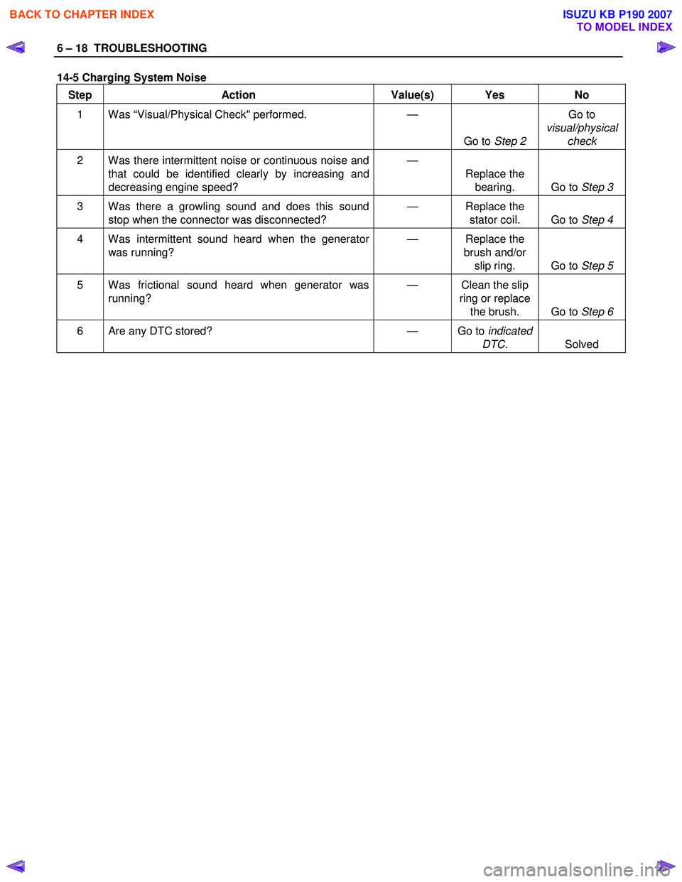
14-5 Charging System Noise Step Action Value(s) Yes No
1 Was “Visual/Physical Check" performed.
—
Go to Step 2 Go to
visual/physical check
2 Was there intermittent noise or continuous noise and
that could be identified clearly by increasing and
decreasing engine speed? —
Replace the bearing. Go to Step 3
3 Was there a growling sound and does this sound
stop when the connector was disconnected? —
Replace the
stator coil. Go to Step 4
4 Was intermittent sound heard when the generator
was running? —
Replace the
brush and/or slip ring. Go to Step 5
5 Was frictional sound heard when generator was
running? —
Clean the slip
ring or replace the brush. Go to Step 6
6 Are any DTC stored? — Go to indicated
DTC. Solved
BACK TO CHAPTER INDEX
TO MODEL INDEX
ISUZU KB P190 2007
Page 804 of 6020
TROUBLESHOOTING 6 – 19
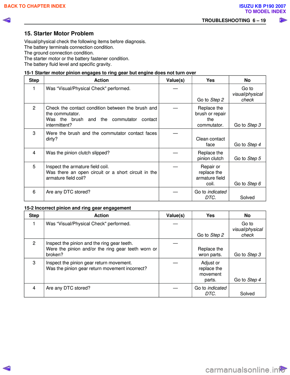
15. Starter Motor Problem
Visual/physical check the following items before diagnosis.
The battery terminals connection condition.
The ground connection condition.
The starter motor or the battery fastener condition.
The battery fluid level and specific gravity.
15-1 Starter motor pinion engages to ring gear but engine does not turn over
Step Action Value(s) Yes No
1 Was “Visual/Physical Check" performed.
—
Go to Step 2 Go to
visual/physical check
2 Check the contact condition between the brush and
the commutator.
Was the brush and the commutator contact
intermittent? —
Replace the
brush or repair the
commutator. Go to Step 3
3 Were the brush and the commutator contact faces
dirty?
—
Clean contact face Go to Step 4
4 Was the pinion clutch slipped? — Replace the
pinion clutch Go to Step 5
5 Inspect the armature field coil.
Was there an open circuit or a short circuit in the
armature field coil? —
Repair or
replace the
armature field coil. Go to Step 6
6 Are any DTC stored? — Go to indicated
DTC. Solved
15-2 Incorrect pinion and ring gear engagement
Step Action Value(s) Yes No
1 Was “Visual/Physical Check" performed.
—
Go to Step 2 Go to
visual/physical check
2 Inspect the pinion and the ring gear teeth.
Were the pinion and/or the ring gear teeth worn or
broken? —
Replace the wron parts. Go to Step 3
3 Inspect the pinion gear return movement.
Was the pinion gear return movement incorrect? —
Adjust or
replace the movement parts. Go to Step 4
4 Are any DTC stored? — Go to indicated
DTC. Solved
BACK TO CHAPTER INDEX
TO MODEL INDEX
ISUZU KB P190 2007