load capacity ISUZU KB P190 2007 Workshop Repair Manual
[x] Cancel search | Manufacturer: ISUZU, Model Year: 2007, Model line: KB P190, Model: ISUZU KB P190 2007Pages: 6020, PDF Size: 70.23 MB
Page 447 of 6020
REAR AXLE 4B-3
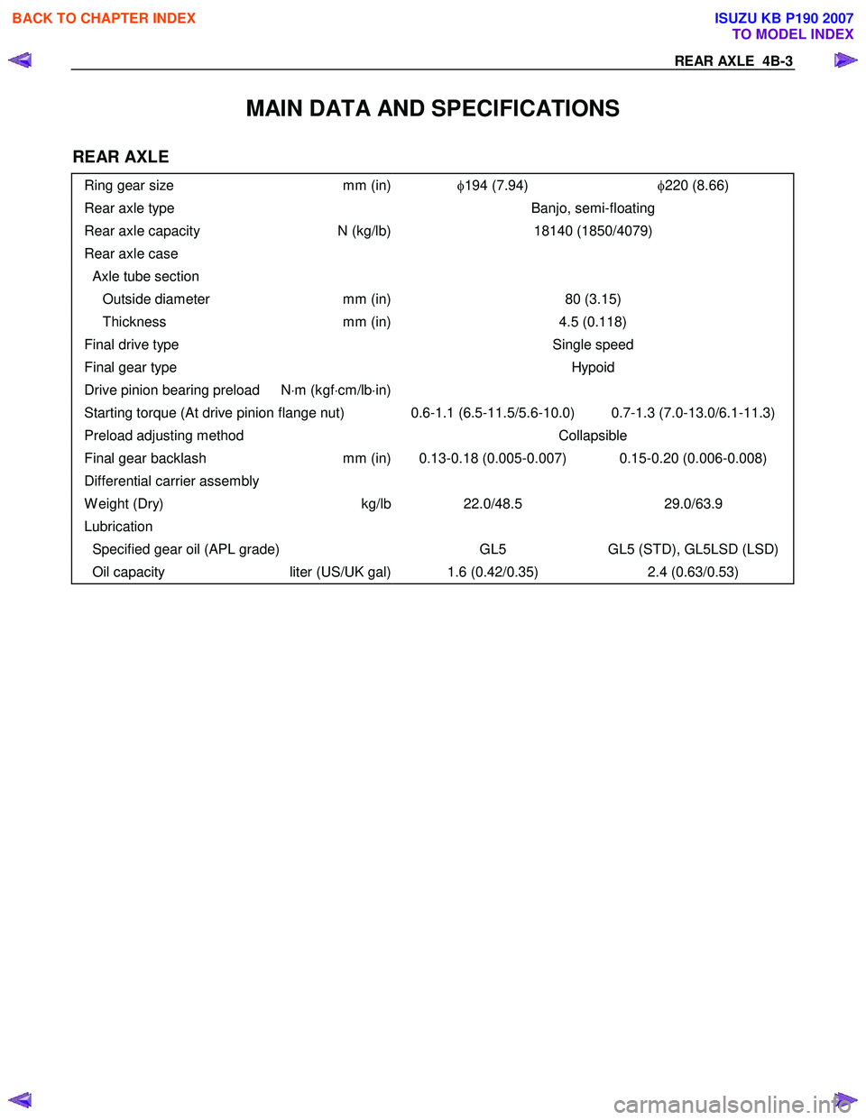
MAIN DATA AND SPECIFICATIONS
REAR AXLE
Ring gear size mm (in)φ194 (7.94) φ220 (8.66)
Rear axle type Banjo, semi-floating
Rear axle capacity N (kg/lb)18140 (1850/4079)
Rear axle case
Axle tube section
Outside diameter mm (in)80 (3.15)
Thickness mm (in)4.5 (0.118)
Final drive type Single speed
Final gear type Hypoid
Drive pinion bearing preload N⋅m (kgf ⋅cm/lb ⋅in)
Starting torque (At drive pinion flange nut) 0.6-1.1 (6.5-11.5/5.6-10.0) 0.7-1.3 (7.0-13.0/6.1-11.3)
Preload adjusting method Collapsible
Final gear backlash mm (in) 0.13-0.18 (0.005-0.007) 0.15-0.20 (0.006-0.008)
Differential carrier assembly
W eight (Dry) kg/lb22.0/48.5 29.0/63.9
Lubrication
Specified gear oil (APL grade) GL5 GL5 (STD), GL5LSD (LSD)
Oil capacity liter (US/UK gal) 1.6 (0.42/0.35) 2.4 (0.63/0.53)
BACK TO CHAPTER INDEX
TO MODEL INDEX
ISUZU KB P190 2007
Page 802 of 6020
TROUBLESHOOTING 6 – 17
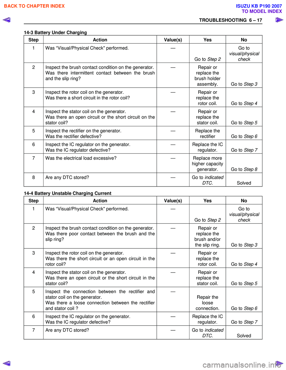
14-3 Battery Under Charging
Step Action Value(s) Yes No
1 Was “Visual/Physical Check" performed.
—
Go to Step 2 Go to
visual/physical check
2 Inspect the brush contact condition on the generator.
Was there intermittent contact between the brush
and the slip ring? —
Repair or
replace the
brush holder assembly. Go to Step 3
3 Inspect the rotor coil on the generator.
Was there a short circuit in the rotor coil? —
Repair or
replace the rotor coil. Go to Step 4
4 Inspect the stator coil on the generator.
Was there an open circuit or the short circuit on the
stator coil? —
Repair or
replace the stator coil. Go to Step 5
5 Inspect the rectifier on the generator.
Was the rectifier defective? —
Replace the
rectifier Go to Step 6
6 Inspect the IC regulator on the generator.
Was the IC regulator defective? —
Replace the IC
regulator. Go to Step 7
7 Was the electrical load excessive? — Replace more
higher capacity generator. Go to Step 8
8 Are any DTC stored? — Go to indicated
DTC. Solved
14-4 Battery Unstable Charging Current
Step Action Value(s) Yes No
1 Was “Visual/Physical Check" performed.
—
Go to Step 2 Go to
visual/physical check
2 Inspect the brush contact condition on the generator.
Was there poor contact between the brush and the
slip ring? —
Repair or
replace the
brush and/or the slip ring. Go to Step 3
3 Inspect the rotor coil on the generator.
Was there the short circuit or an open circuit in the
rotor coil? —
Repair or
replace the rotor coil. Go to Step 4
4 Inspect the stator coil on the generator.
Was there an open circuit or the short circuit in the
stator coil? —
Repair or
replace the stator coil. Go to Step 5
5 Inspect the connection between the rectifier and
stator coil on the generator.
Was there a loose connection between the rectifier
and stator coil ? —
Repair the loose
connection. Go to Step 6
6 Inspect the IC regulator on the generator.
Was the IC regulator defective? —
Replace the IC
regulator. Go to Step 7
7 Are any DTC stored? — Go to indicated
DTC. Solved
BACK TO CHAPTER INDEX
TO MODEL INDEX
ISUZU KB P190 2007
Page 1310 of 6020
6E-276 Engine Control System (4JH1)
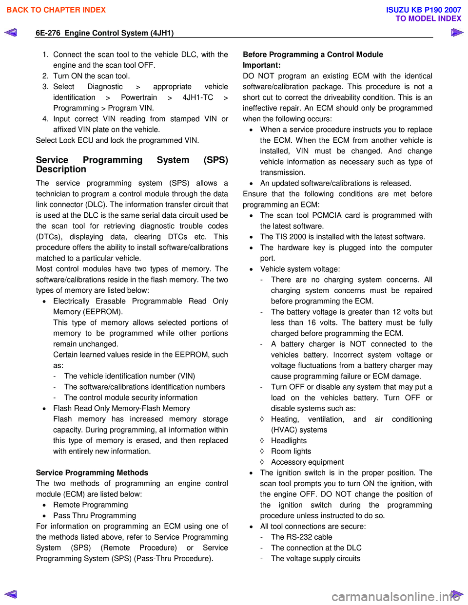
1. Connect the scan tool to the vehicle DLC, with theengine and the scan tool OFF.
2. Turn ON the scan tool.
3. Select Diagnostic > appropriate vehicle identification > Powertrain > 4JH1-TC >
Programming > Program VIN.
4. Input correct VIN reading from stamped VIN o
r
affixed VIN plate on the vehicle.
Select Lock ECU and lock the programmed VIN.
Service Programming System (SPS)
Description
The service programming system (SPS) allows a
technician to program a control module through the data
link connector (DLC). The information transfer circuit that
is used at the DLC is the same serial data circuit used be
the scan tool for retrieving diagnostic trouble codes
(DTCs), displaying data, clearing DTCs etc. This
procedure offers the ability to install software/calibrations
matched to a particular vehicle.
Most control modules have two types of memory. The
software/calibrations reside in the flash memory. The two
types of memory are listed below: • Electrically Erasable Programmable Read Onl
y
Memory (EEPROM).
This type of memory allows selected portions o
f
memory to be programmed while other portions
remain unchanged.
Certain learned values reside in the EEPROM, such as:
- The vehicle identification number (VIN)
- The software/calibrations identification numbers
- The control module security information
• Flash Read Only Memory-Flash Memory
Flash memory has increased memory storage capacity. During programming, all information within
this type of memory is erased, and then replaced
with entirely new information.
Service Programming Methods
The two methods of programming an engine control
module (ECM) are listed below: • Remote Programming
• Pass Thru Programming
For information on programming an ECM using one o
f
the methods listed above, refer to Service Programming
System (SPS) (Remote Procedure) or Service
Programming System (SPS) (Pass-Thru Procedure).
Before Programming a Control Module
Important:
DO NOT program an existing ECM with the identical
software/calibration package. This procedure is not a
short cut to correct the driveability condition. This is an
ineffective repair. An ECM should only be programmed
when the following occurs: • W hen a service procedure instructs you to replace
the ECM. W hen the ECM from another vehicle is
installed, VIN must be changed. And change
vehicle information as necessary such as type o
f
transmission.
• An updated software/calibrations is released.
Ensure that the following conditions are met before
programming an ECM: • The scan tool PCMCIA card is programmed with
the latest software.
• The TIS 2000 is installed with the latest software.
• The hardware key is plugged into the compute
r
port.
• Vehicle system voltage:
- There are no charging system concerns. All charging system concerns must be repaired
before programming the ECM.
- The battery voltage is greater than 12 volts bu
t
less than 16 volts. The battery must be fully
charged before programming the ECM.
-
A battery charger is NOT connected to the
vehicles battery. Incorrect system voltage o
r
voltage fluctuations from a battery charger may
cause programming failure or ECM damage.
- Turn OFF or disable any system that may put a load on the vehicles battery. Turn OFF o
r
disable systems such as:
◊ Heating, ventilation, and air conditioning
(HVAC) systems
◊ Headlights
◊ Room lights
◊ Accessory equipment
• The ignition switch is in the proper position. The
scan tool prompts you to turn ON the ignition, with
the engine OFF. DO NOT change the position o
f
the ignition switch during the programming
procedure unless instructed to do so.
• All tool connections are secure:
- The RS-232 cable
- The connection at the DLC
- The voltage supply circuits
BACK TO CHAPTER INDEX
TO MODEL INDEX
ISUZU KB P190 2007
Page 2524 of 6020
Engine Mechanical – V6 Page 6A1–45
Step Action Yes No
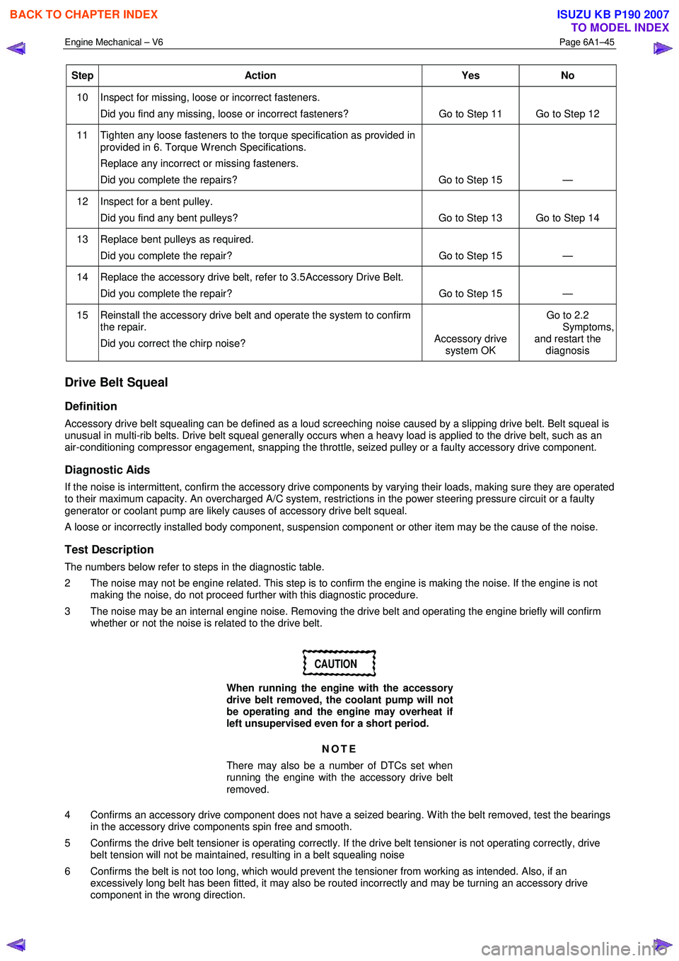
10 Inspect for missing, loose or incorrect fasteners.
Did you find any missing, loose or incorrect fasteners? Go to Step 11 Go to Step 12
11 Tighten any loose fasteners to the torque specification as provided in
provided in 6. Torque W rench Specifications.
Replace any incorrect or missing fasteners.
Did you complete the repairs? Go to Step 15 —
12 Inspect for a bent pulley. Did you find any bent pulleys? Go to Step 13 Go to Step 14
13 Replace bent pulleys as required. Did you complete the repair? Go to Step 15 —
14 Replace the accessory drive belt, refer to 3.5 Accessory Drive Belt.
Did you complete the repair? Go to Step 15 —
15 Reinstall the accessory drive belt and operate the system to confirm the repair.
Did you correct the chirp noise? Accessory drive
system OK Go to 2.2
Symptoms, and restart the
diagnosis
Drive Belt Squeal
Definition
Accessory drive belt squealing can be defined as a loud screeching noise caused by a slipping drive belt. Belt squeal is
unusual in multi-rib belts. Drive belt squeal generally occurs when a heavy load is applied to the drive belt, such as an
air-conditioning compressor engagement, snapping the throttle, seized pulley or a faulty accessory drive component.
Diagnostic Aids
If the noise is intermittent, confirm the accessory drive components by varying their loads, making sure they are operated
to their maximum capacity. An overcharged A/C system, restrictions in the power steering pressure circuit or a faulty
generator or coolant pump are likely causes of accessory drive belt squeal.
A loose or incorrectly installed body component, suspension component or other item may be the cause of the noise.
Test Description
The numbers below refer to steps in the diagnostic table.
2 The noise may not be engine related. This step is to confirm the engine is making the noise. If the engine is not making the noise, do not proceed further with this diagnostic procedure.
3 The noise may be an internal engine noise. Removing the drive belt and operating the engine briefly will confirm whether or not the noise is related to the drive belt.
CAUTION
When running the engine with the accessory
drive belt removed, the coolant pump will not
be operating and the engine may overheat if
left unsupervised even for a short period.
NOTE
There may also be a number of DTCs set when
running the engine with the accessory drive belt
removed.
4 Confirms an accessory drive component does not have a seized bearing. W ith the belt removed, test the bearings in the accessory drive components spin free and smooth.
5 Confirms the drive belt tensioner is operating correctly. If the drive belt tensioner is not operating correctly, drive belt tension will not be maintained, resulting in a belt squealing noise
6 Confirms the belt is not too long, which would prevent the tensioner from working as intended. Also, if an excessively long belt has been fitted, it may also be routed incorrectly and may be turning an accessory drive
component in the wrong direction.
BACK TO CHAPTER INDEX
TO MODEL INDEX
ISUZU KB P190 2007
Page 2525 of 6020
Engine Mechanical – V6 Page 6A1–46
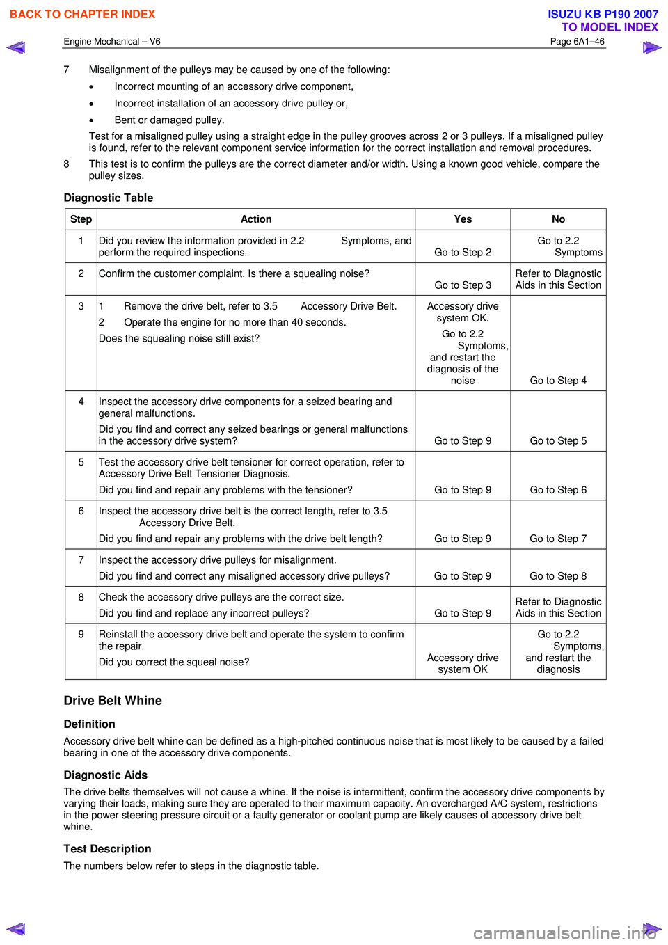
7 Misalignment of the pulleys may be caused by one of the following:
• Incorrect mounting of an accessory drive component,
• Incorrect installation of an accessory drive pulley or,
• Bent or damaged pulley.
Test for a misaligned pulley using a straight edge in the pulley grooves across 2 or 3 pulleys. If a misaligned pulley is found, refer to the relevant component service information for the correct installation and removal procedures.
8 This test is to confirm the pulleys are the correct diameter and/or width. Using a known good vehicle, compare the pulley sizes.
Diagnostic Table
Step Action Yes No
1 Did you review the information provided in 2.2 Symptoms, and
perform the required inspections. Go to Step 2 Go to 2.2
Symptoms
2 Confirm the customer complaint. Is there a squealing noise? Go to Step 3 Refer to Diagnostic
Aids in this Section
3 1 Remove the drive belt, refer to 3.5 Accessory Drive Belt.
2 Operate the engine for no more than 40 seconds.
Does the squealing noise still exist? Accessory drive
system OK.
Go to 2.2
Symptoms, and restart the
diagnosis of the noise Go to Step 4
4 Inspect the accessory drive components for a seized bearing and
general malfunctions.
Did you find and correct any seized bearings or general malfunctions
in the accessory drive system? Go to Step 9 Go to Step 5
5 Test the accessory drive belt tensioner for correct operation, refer to
Accessory Drive Belt Tensioner Diagnosis.
Did you find and repair any problems with the tensioner? Go to Step 9 Go to Step 6
6 Inspect the accessory drive belt is the correct length, refer to 3.5
Accessory Drive Belt.
Did you find and repair any problems with the drive belt length? Go to Step 9 Go to Step 7
7 Inspect the accessory drive pulleys for misalignment.
Did you find and correct any misaligned accessory drive pulleys? Go to Step 9 Go to Step 8
8 Check the accessory drive pulleys are the correct size. Did you find and replace any incorrect pulleys? Go to Step 9 Refer to Diagnostic
Aids in this Section
9 Reinstall the accessory drive belt and operate the system to confirm
the repair.
Did you correct the squeal noise? Accessory drive
system OK Go to 2.2
Symptoms, and restart the diagnosis
Drive Belt Whine
Definition
Accessory drive belt whine can be defined as a high-pitched continuous noise that is most likely to be caused by a failed
bearing in one of the accessory drive components.
Diagnostic Aids
The drive belts themselves will not cause a whine. If the noise is intermittent, confirm the accessory drive components by
varying their loads, making sure they are operated to their maximum capacity. An overcharged A/C system, restrictions
in the power steering pressure circuit or a faulty generator or coolant pump are likely causes of accessory drive belt
whine.
Test Description
The numbers below refer to steps in the diagnostic table.
BACK TO CHAPTER INDEX
TO MODEL INDEX
ISUZU KB P190 2007
Page 2769 of 6020
Engine Mechanical – V6 Page 6A1–290
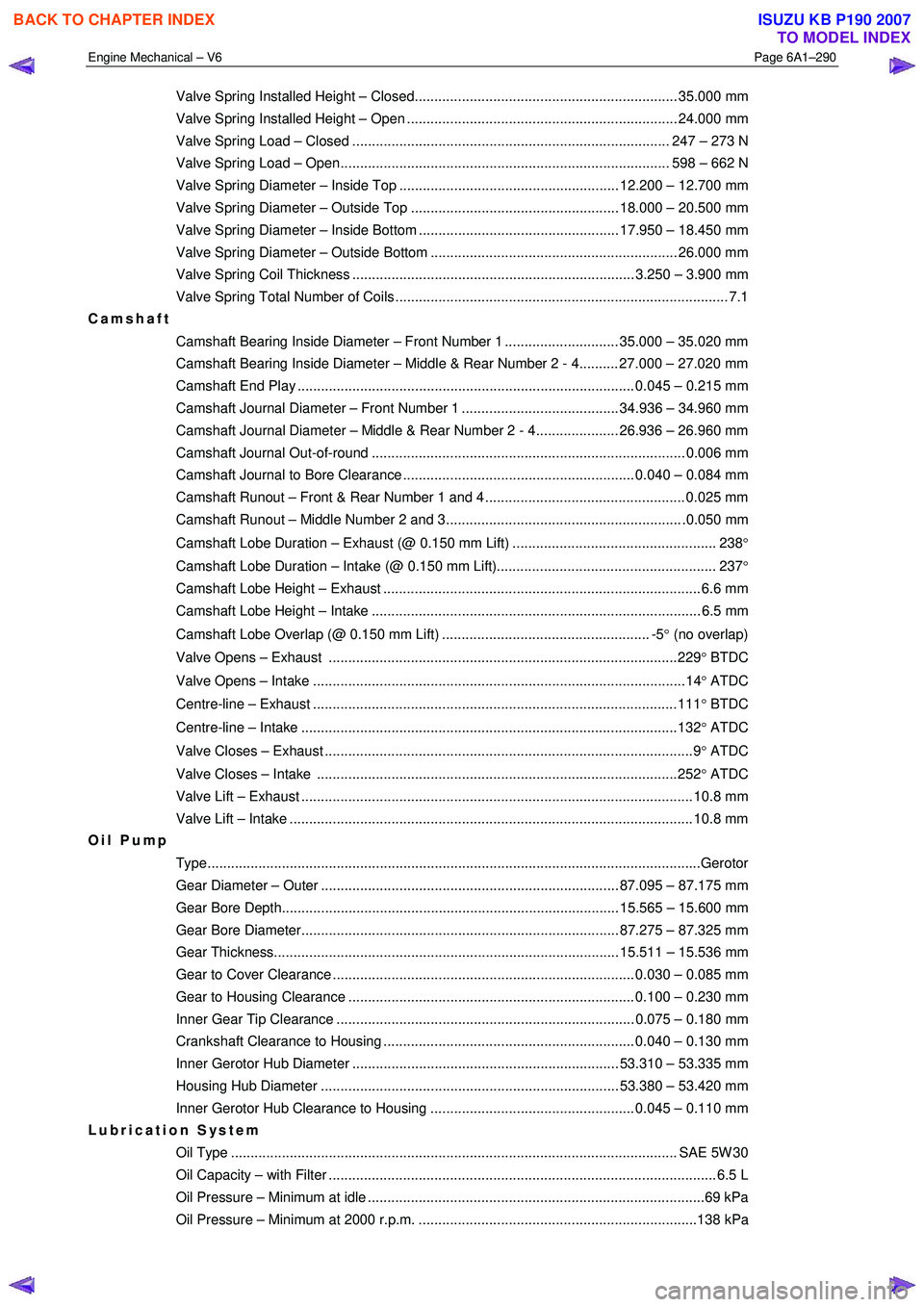
Valve Spring Installed Height – Closed................................................................... 35.000 mm
Valve Spring Installed Height – Open ..................................................................... 24.000 mm
Valve Spring Load – Closed ................................................................................. 247 – 273 N
Valve Spring Load – Open.................................................................................... 598 – 662 N
Valve Spring Diameter – Inside Top ........................................................ 12.200 – 12.700 mm
Valve Spring Diameter – Outside Top ..................................................... 18.000 – 20.500 mm
Valve Spring Diameter – Inside Bottom ................................................... 17.950 – 18.450 mm
Valve Spring Diameter – Outside Bottom ............................................................... 26.000 mm
Valve Spring Coil Thickness ........................................................................ 3.250 – 3.900 mm
Valve Spring Total Number of Coils ..................................................................................... 7.1
Camshaft
Camshaft Bearing Inside Diameter – Front Number 1 ............................. 35.000 – 35.020 mm
Camshaft Bearing Inside Diameter – Middle & Rear Number 2 - 4.......... 27.000 – 27.020 mm
Camshaft End Play ...................................................................................... 0.045 – 0.215 mm
Camshaft Journal Diameter – Front Number 1 ........................................ 34.936 – 34.960 mm
Camshaft Journal Diameter – Middle & Rear Number 2 - 4..................... 26.936 – 26.960 mm
Camshaft Journal Out-of-round ................................................................................ 0.006 mm
Camshaft Journal to Bore Clearance ........................................................... 0.040 – 0.084 mm
Camshaft Runout – Front & Rear Number 1 and 4 ................................................... 0.025 mm
Camshaft Runout – Middle Number 2 and 3............................................................ .0.050 mm
Camshaft Lobe Duration – Exhaust (@ 0.150 mm Lift) .................................................... 238 °
Camshaft Lobe Duration – Intake (@ 0.150 mm Lift)........................................................ 237 °
Camshaft Lobe Height – Exhaust ................................................................................. 6.6 mm
Camshaft Lobe Height – Intake .................................................................................... 6.5 mm
Camshaft Lobe Overlap (@ 0.150 mm Lift) ..................................................... -5 ° (no overlap)
Valve Opens – Exhaust .........................................................................................229 ° BTDC
Valve Opens – Intake ...............................................................................................14 ° ATDC
Centre-line – Exhaust .............................................................................................111 ° BTDC
Centre-line – Intake ................................................................................................132 ° ATDC
Valve Closes – Exhaust ..............................................................................................9 ° ATDC
Valve Closes – Intake ............................................................................................252 ° ATDC
Valve Lift – Exhaust .................................................................................................... 10.8 mm
Valve Lift – Intake ....................................................................................................... 10.8 mm
Oil Pump
Type........................................................................................................................... ...Gerotor
Gear Diameter – Outer ............................................................................ 87.095 – 87.175 mm
Gear Bore Depth...................................................................................... 15.565 – 15.600 mm
Gear Bore Diameter................................................................................. 87.275 – 87.325 mm
Gear Thickness........................................................................................ 15.511 – 15.536 mm
Gear to Cover Clearance ............................................................................. 0.030 – 0.085 mm
Gear to Housing Clearance ......................................................................... 0.100 – 0.230 mm
Inner Gear Tip Clearance ............................................................................ 0.075 – 0.180 mm
Crankshaft Clearance to Housing ................................................................ 0.040 – 0.130 mm
Inner Gerotor Hub Diameter .................................................................... 53.310 – 53.335 mm
Housing Hub Diameter ............................................................................ 53.380 – 53.420 mm
Inner Gerotor Hub Clearance to Housing .................................................... 0.045 – 0.110 mm
Lubrication System
Oil Type .................................................................................................................. SAE 5 W 30
Oil Capacity – with Filter ................................................................................................... 6. 5 L
Oil Pressure – Minimum at idle ......................................................................................69 kPa
Oil Pressure – Minimum at 2000 r.p.m. .......................................................................138 kPa
BACK TO CHAPTER INDEX
TO MODEL INDEX
ISUZU KB P190 2007
Page 2832 of 6020
Engine Mechanical – V6 Page 6A1–55
Page 6A1–55
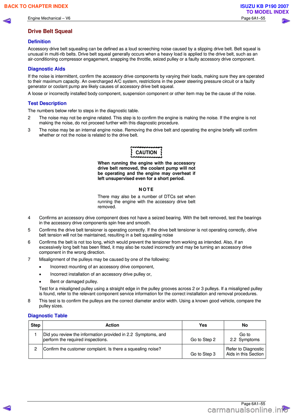
Drive Belt Squeal
Definition
Accessory drive belt squealing can be defined as a loud screeching noise caused by a slipping drive belt. Belt squeal is
unusual in multi-rib belts. Drive belt squeal generally occurs when a heavy load is applied to the drive belt, such as an
air-conditioning compressor engagement, snapping the throttle, se ized pulley or a faulty accessory drive component.
Diagnostic Aids
If the noise is intermittent, confirm the accessory drive components by varying t heir loads, making sure they are operated
to their maximum capacity. An overcharged A/C system, restrictions in the power steering pressure circuit or a faulty
generator or coolant pump are likely c auses of accessory drive belt squeal.
A loose or incorrectly installed body component, suspension component or other item may be the cause of the noise.
Test Description
The numbers below refer to steps in the diagnostic table.
2 The noise may not be engine related. This step is to confirm the engine is making t he noise. If the engine is not
making the noise, do not proceed further with this diagnostic procedure.
3 The noise may be an internal engine noise. Removing the drive belt and operating the engine briefly will confirm
whether or not the noise is related to the drive belt.
CAUTION
When running the engine with the accessory
drive belt removed, the coolant pump will not
be operating and the engine may overheat if
left unsupervised even for a short period.
NOTE
There may also be a number of DTCs set when
running the engine with the accessory drive belt
removed.
4 Confirms an accessory drive component does not have a se ized bearing. With the belt removed, test the bearings
in the accessory drive co mponents spin free and smooth.
5 Confirms the drive belt tensioner is operating correctly. If the drive belt tensioner is not operating correctly, drive
belt tension will not be maintained, resulting in a belt squealing noise
6 Confirms the belt is not too long, which would prevent the tensioner from working as intended. Also, if an
excessively long belt has been fitted, it may also be r outed incorrectly and may be turning an accessory drive
component in the wrong direction.
7 Misalignment of the pulleys may be caused by one of the following:
• Incorrect mounting of an accessory drive component,
• Incorrect installation of an accessory drive pulley or,
• Bent or damaged pulley.
Test for a misaligned pulley using a straight edge in the pulley grooves across 2 or 3 pulleys. If a misaligned pulley is found, refer to the relevant component service info rmation for the correct installation and removal procedures.
8 This test is to confirm the pulleys are the correct di ameter and/or width. Using a known good vehicle, compare the
pulley sizes.
Diagnostic Table
Step Action Yes No
1
Did you review the information provided in 2.2 Symptoms, and
perform the required inspections. Go to Step 2 Go to
2.2 Symptoms
2 Confirm the customer compla int. Is there a squealing noise?
Go to Step 3 Refer to Diagnostic
Aids in this Section
BACK TO CHAPTER INDEX
TO MODEL INDEX
ISUZU KB P190 2007
Page 2834 of 6020
Engine Mechanical – V6 Page 6A1–57
Page 6A1–57
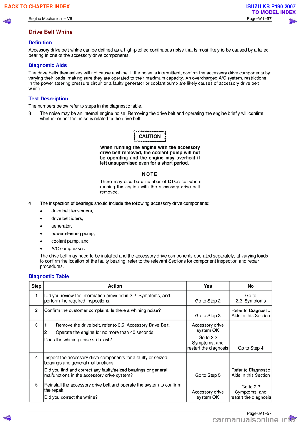
Drive Belt Whine
Definition
Accessory drive belt whine can be defined as a high-pitched continuous noise that is most likely to be caused by a failed
bearing in one of the acce ssory drive components.
Diagnostic Aids
The drive belts themselves will not caus e a whine. If the noise is intermittent, confirm the accessory drive components by
varying their loads, making sure they are operated to their maximum capacity. An overcharged A/C system, restrictions
in the power steering pressure circuit or a faulty generator or coolant pump ar e likely causes of accessory drive belt
whine.
Test Description
The numbers below refer to steps in the diagnostic table.
3 The noise may be an internal engine noise. Removing the drive belt and operating the engine briefly will confirm
whether or not the noise is related to the drive belt.
CAUTION
When running the engine with the accessory
drive belt removed, the coolant pump will not
be operating and the engine may overheat if
left unsupervised even for a short period.
NOTE
There may also be a number of DTCs set when
running the engine with the accessory drive belt
removed.
4 The inspection of bearings should include the following accessory drive components:
• drive belt tensioners,
• drive belt idlers,
• generator,
• power steering pump,
• coolant pump, and
• A/C compressor.
The drive belt may need to be installed and the accessory drive components operated separ ately, at varying loads
to confirm the location of the faulty bearing, refer to the relevant Sections for component inspection and repair
procedures.
Diagnostic Table
Step Action Yes No
1
Did you review the information provided in 2.2 Symptoms, and
perform the required inspections. Go to Step 2 Go to
2.2 Symptoms
2 Confirm the customer compla int. Is there a whining noise?
Go to Step 3 Refer to Diagnostic
Aids in this Section
3 1 Remove the drive belt, refer to 3.5 Accessory Drive Belt.
2 Operate the engine for no more than 40 seconds.
Does the whining noise still exist? Accessory drive
system OK
Go to 2.2
Symptoms, and
restart the diagnosis Go to Step 4
4 Inspect the accessory drive components for a faulty or seized
bearings and general malfunctions.
Did you find and correct any faulty/seized bearings or general
malfunctions in the accessory drive system? Go to Step 5 Refer to Diagnostic
Aids in this Section
5 Reinstall the accessory drive belt and operate the system to confirm
the repair.
Did you correct the whine? Accessory drive
system OK Go to 2.2
Symptoms, and
restart the diagnosis
BACK TO CHAPTER INDEX
TO MODEL INDEX
ISUZU KB P190 2007
Page 3641 of 6020
Battery Page 6D1-3–1
6D1-3
Battery – V6
ATTENTION
Before performing any service operation or other procedure described in this Section, refer to 1.1
WARNING, CAUTION and NOTES for correct workshop practices with regard to safety and/or property
damage.
1 General Information ............................................................................................................ ...................3
1.1 WARNING, CAUTION and NOTES ..................................................................................................... ................... 3
Definition of WARNING, CAUTION and NOTE Statements ............................................................................. .... 3
1.2 Battery Terminals and Cables............................................................................................................................... 4
1.3 Battery Ratings ...................................................................................................................................................... 4
Reserve Capacity ............................................................................................................... .................................... 4
Cold Cranking Amps ............................................................................................................................................. 5
Ratings.................................................................................................................................................................... 5
2 Safety Precautions .................................................................................................................................6
3 Diagnosis ................................................................................................................................................7
3.1 Diagnostic Procedures .......................................................................................................................................... 7
Introduction ............................................................................................................................................................ 7
Test Description ..................................................................................................................................................... 7
Diagnostic Table Notes ......................................................................................................................................... 7
Diagnostic Table .................................................................................................................................................... 7
3.2 Battery Inspection.................................................................................................................................................. 8
3.3 Hydrometer Test .................................................................................................................................................... 9
3.4 Load Test ...................................................................................................................... ........................................ 10
High Rate Discharge Load Test .................................................................................................. ........................ 10
Alternate Load Test ............................................................................................................................................. 11
3.5 Battery Current Draw Test...................................................................................................... ............................. 11
Test Preparation................................................................................................................................................... 11
Test Procedure ..................................................................................................................................................... 12
Fault Diagnosis .................................................................................................................................................... 12
Restore.................................................................................................................................................................. 13
4 Service Operations ...............................................................................................................................14
4.1 Battery................................................................................................................................................................... 14
Remove ......................................................................................................................... ........................................ 14
Reinstall ................................................................................................................................................................ 14
4.2 Battery Charge ................................................................................................................. .................................... 15
Safety Precautions............................................................................................................. .................................. 15
Battery Charge Procedure....................................................................................................... ............................ 15
4.3 Emergency Jump Starting Procedure .............................................................................................. .................. 16
Safety Precautions............................................................................................................................................... 16
Jump Starting Procedure ........................................................................................................ ............................ 16
4.4 Dry Charged Batteries ......................................................................................................................................... 18
Storage.................................................................................................................................................................. 18
Activation..................................................................................................................... ......................................... 18
Post Activation Tests .......................................................................................................... ................................ 18
5 Specifications .......................................................................................................................................19
BACK TO CHAPTER INDEX
TO MODEL INDEX
ISUZU KB P190 2007
Page 3644 of 6020
Battery Page 6D1-3–4
• Clarify a procedure,
• Present additional information for accomplishing a procedure,
• Give insight into the reasons for performing a procedure in the recommended manner, and / or
Present information that gives the technician the benefit of past experience in accomplishing a procedure with greater
ease.
1.2 Battery Terminals and Cables
The cables attached to the battery posts provide power and ground connections for the vehicle electrical system. These
battery cables attach to the battery posts via nut-tightened terminals. The battery is held in position by a hold-down
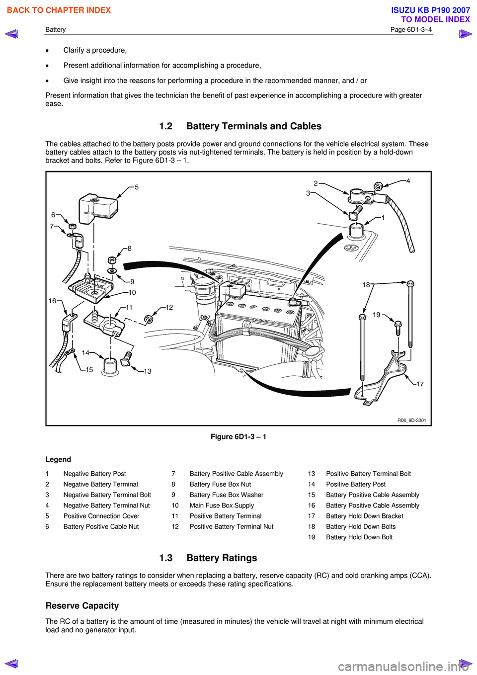
bracket and bolts. Refer to Figure 6D1-3 – 1.
Figure 6D1-3 – 1
Legend
1 Negative Battery Post
2 Negative Battery Terminal
3 Negative Battery Terminal Bolt
4 Negative Battery Terminal Nut
5 Positive Connection Cover
6 Battery Positive Cable Nut 7 Battery Positive Cable Assembly
8 Battery Fuse Box Nut
9 Battery Fuse Box Washer
10 Main Fuse Box Supply
11 Positive Battery Terminal
12 Positive Battery Terminal Nut 13 Positive Battery Terminal Bolt
14 Positive Battery Post
15 Battery Positive Cable Assembly
16 Battery Positive Cable Assembly
17 Battery Hold Down Bracket
18 Battery Hold Down Bolts
19 Battery Hold Down Bolt
1.3 Battery Ratings
There are two battery ratings to consider when replacing a battery, reserve capacity (RC) and cold cranking amps (CCA).
Ensure the replacement battery meets or exceeds these rating specifications.
Reserve Capacity
The RC of a battery is the amount of time (measured in minutes) the vehicle will travel at night with minimum electrical
load and no generator input.
BACK TO CHAPTER INDEX
TO MODEL INDEX
ISUZU KB P190 2007