display ISUZU KB P190 2007 Workshop Manual PDF
[x] Cancel search | Manufacturer: ISUZU, Model Year: 2007, Model line: KB P190, Model: ISUZU KB P190 2007Pages: 6020, PDF Size: 70.23 MB
Page 1972 of 6020
ENGINE CONTROL SYSTEM (4JK1/4JJ1) 6E-355
Electrostatic Discharge Damage
Electronic components used in the ECM are often
designed to carry very low voltage. Electronic
components are susceptible to damage caused by
electrostatic discharge. By comparison, as much as
4,000 volts may be needed for a person to feel even
the zap of a static discharge. There are several ways
for a person to become statically charged. The most
common methods of charging are by friction and
induction.
• An example of charging by friction is a person sliding across a vehicle seat.
Important: To prevent possible electrostatic discharge
damage, follow these guidelines:
• Do not touch the ECM connector pins or soldered components on the ECM circuit board.
• Do not open the replacement part package until the part is ready to be installed.
• Before removing the part from the package, ground the package to a known good ground on
the vehicle.
• If the part has been handled while sliding across the seat, while sitting down from a standing
position, or while walking a distance, touch a
known good ground before installing the part.
• Charge by induction occurs when a person with well insulated shoes stands near a highly charged
object and momentarily touches ground. Charges
of the same polarity are drained off leaving the
person highly charged with opposite polarity.
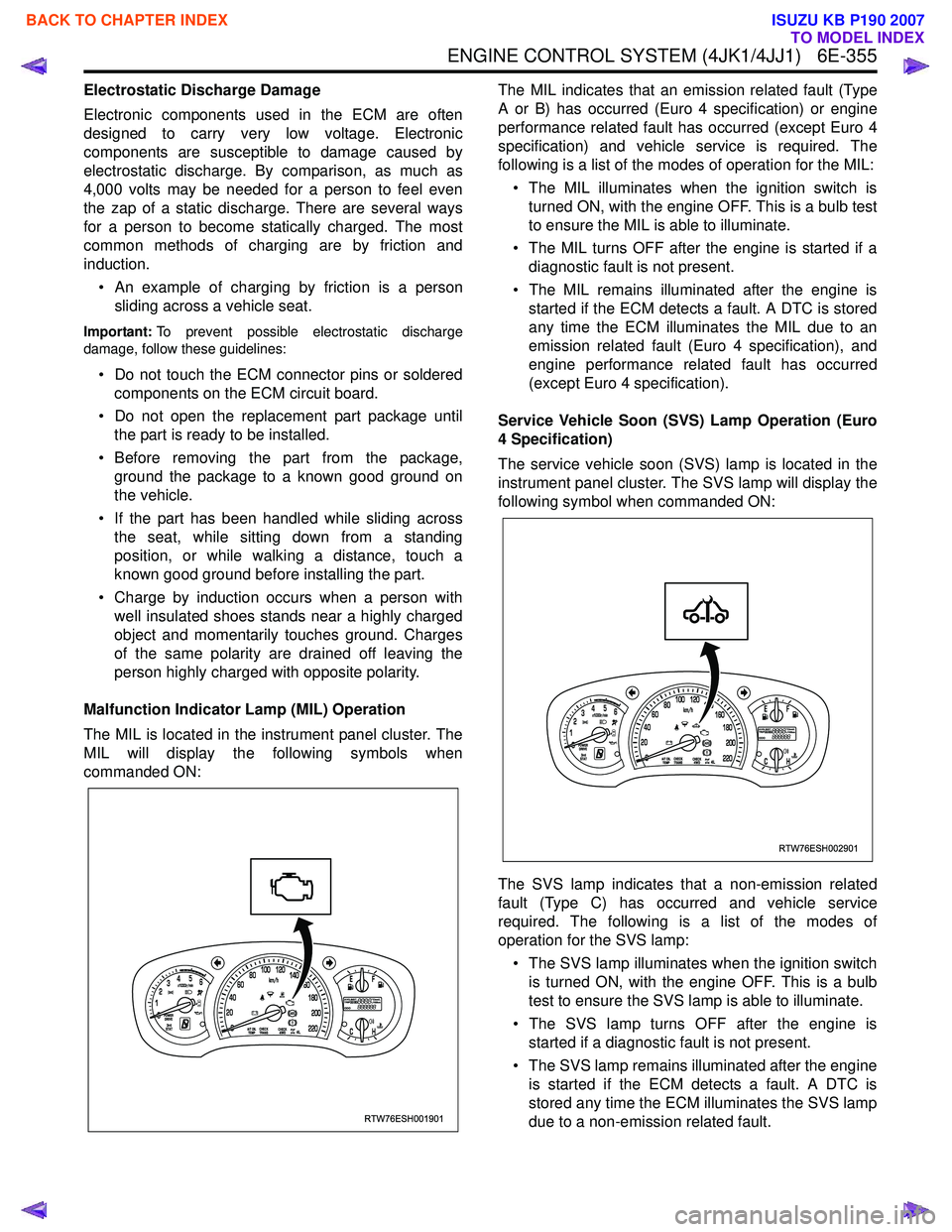
Malfunction Indicator Lamp (MIL) Operation
The MIL is located in the instrument panel cluster. The
MIL will display the following symbols when
commanded ON: The MIL indicates that an emission related fault (Type
A or B) has occurred (Euro 4 specification) or engine
performance related fault has occurred (except Euro 4
specification) and vehicle service is required. The
following is a list of the modes of operation for the MIL:
• The MIL illuminates when the ignition switch is turned ON, with the engine OFF. This is a bulb test
to ensure the MIL is able to illuminate.
• The MIL turns OFF after the engine is started if a diagnostic fault is not present.
• The MIL remains illuminated after the engine is started if the ECM detects a fault. A DTC is stored
any time the ECM illuminates the MIL due to an
emission related fault (Euro 4 specification), and
engine performance related fault has occurred
(except Euro 4 specification).
Service Vehicle Soon (SVS) Lamp Operation (Euro
4 Specification)
The service vehicle soon (SVS) lamp is located in the
instrument panel cluster. The SVS lamp will display the
following symbol when commanded ON:
The SVS lamp indicates that a non-emission related
fault (Type C) has occurred and vehicle service
required. The following is a list of the modes of
operation for the SVS lamp:
• The SVS lamp illuminates when the ignition switch is turned ON, with the engine OFF. This is a bulb
test to ensure the SVS lamp is able to illuminate.
• The SVS lamp turns OFF after the engine is started if a diagnostic fault is not present.
• The SVS lamp remains illuminated after the engine is started if the ECM detects a fault. A DTC is
stored any time the ECM illuminates the SVS lamp
due to a non-emission related fault.
RTW76ESH001901
RTW76ESH002901
BACK TO CHAPTER INDEX
TO MODEL INDEX
ISUZU KB P190 2007
Page 1977 of 6020

6E-360 ENGINE CONTROL SYSTEM (4JK1/4JJ1)
1. High Pressure Control• Enables high pressure injection from low engine speed range.
• Optimizes control to minimize particulate matter and NOx emissions.
2. Injection Timing Control
• Enables finely tuned optimized control in accordance with running conditions.
3. Injection Rate Control
• Pilot injection control that performs a small amount of injection before main injection.
The fuel rail system consists primarily of a fuel supply
pump, fuel rail, injectors, and ECM.
Fuel System Component Description
Injector
Legend
1. Fuel injector ID code
2. Leak off pipe
3. Two dimensional barcode
4. Port for mounting the injection pipe
5. O-ring
Electronic control type injectors controlled by the ECM
are used. Compared with conventional injection
nozzles, a command piston, solenoid valve, etc. are
added.
ID codes displaying various injector characteristic are
laser marked on the connector housing, and ID codes showing these in numeric form (24 alphanumeric
figures). This system uses fuel injector flow rate
information (ID codes) to optimize injection quantity
control. When an injector is newly installed in a vehicle,
it is necessary to input the ID codes in the ECM.
QR (Quick Response) codes or fuel injector flow rate
(ID codes) have been adopted to enhance the injection
quantity precision of the injectors. The adoption of
codes enables injection quantity dispersion control
throughout all pressure ranges, contributing to
improvement in combustion efficiency and reduction in
exhaust gas emissions.
RTW56EMH000101
23
1
4
5
BACK TO CHAPTER INDEX
TO MODEL INDEX
ISUZU KB P190 2007
Page 2172 of 6020

6E–2 ENGINE DRIVEABILITY AND EMISSIONS
5e. Vehicle Operates as Designed ............ 6E-65
6. Re-examine the complaint ..................... 6E-66
7. Repair and Verify Fix ............................. 6E-66
GENERAL SERVICE INFORMATION .......... 6E-67 On-Board Diagnostic (OBD) ...................... 6E-68
On-Board Diagnostic Tests ....................... 6E-68
The Diagnostic Executive .......................... 6E-68
Diagnostic Information ............................... 6E-68
Check Engine Lamp .................................. 6E-68
Data Link Connector (DLC) ....................... 6E-68
Tech 2 Operating Flow Cart (Start Up) ...... 6E-70
TYPICAL SCAN DATA & DEFINITIONS (ENGINE DATA) ......................................... 6E-72
TYPICAL SCAN DATA & DEFINITIONS (O2 SENSOR DATA) .................................. 6E-74
MISCELLANEOUS TEST ............................. 6E-76
PLOTTING SNAPSHOT GRAPH ................. 6E-78 Plotting Graph Flow Chart (Plotting graph after obtaining vehicle information) .................. 6E-79
Flow Chart for Snapshot Replay (Plotting Graph) ....................................... 6E-80
SNAPSHOT DISPLAY WITH TIS2000 ......... 6E-81
ON-BOARD DIAGNOSTIC (OBD) SYSTEM CHECK 6E-98
Circuit Description ......................................... 6E-90
Diagnostic Aids ............................................. 6E-90
Test Description ............................................ 6E-90
ON-BOARD DIAGNOSTIC (OBD) SYSTEM CHECK .................................................... 6E-91
NO CHECK ENGINE LAMP (MIL) ................ 6E-94 Circuit Description ..................................... 6E-94
Diagnostic Aids .......................................... 6E-94
No Check Engine Lamp (MIL) ................... 6E-94
CHECK ENGINE LAMP (MIL) “ON” STEADY 6E-96 Circuit description ...................................... 6E-96
Diagnostic Aids .......................................... 6E-96
Check Engine Lamp (MIL) “ON” Steady .... 6E-96
FUEL METERING SYSTEM CHECK ........... 6E-98
FUEL INJECTOR COIL TEST PROCEDURE AND FUEL INJECTOR BALANCE TEST
PROCEDURE ............................................. 6E-98
Test Description ......................................... 6E-98
Injector Coil Test Procedure (Steps 1-6) and Injector Balance Test Procedure
(Steps 7-11) ............................................. 6E-99
Injector Coil Test Procedure (Steps 1-6) and Injector Balance Test Procedure
(Steps 7-11) ............................................. 6E-100
FUEL SYSTEM ELECTRICAL TEST ........... 6E-103 Circuit Description ..................................... 6E-103
Diagnostic Aids .......................................... 6E-104 Fuel Pressure Relief Procedure ................. 6E-104
Fuel Pressure Gauge Installation .............. 6E-104
Fuel System Electrical Test ....................... 6E-104
FUEL SYSTEM DIAGNOSIS ........................ 6E-108 Circuit Description ...................................... 6E-108
Test Description ......................................... 6E-108
Fuel Pressure Relief Procedure ................. 6E-109
Fuel Pressure Gauge Installation .............. 6E-109
Fuel System Diagnosis .............................. 6E-110
ECM DIAGNOSTIC TROUBLE CODES (DTC) 6E-113
DIAGNOSTIC TROUBLE CODE (DTC) P0107 MANIFOLD ABSOLUTE PRESSURE
CIRCUIT LOW INPUT ................................ 6E-119
Circuit Description ...................................... 6E-119
Diagnostic Aids .......................................... 6E-119
Diagnostic Trouble Code (DTC) P0107 Manifold Absolute Pressure Circuit Low
Input ......................................................... 6E-120
DIAGNOSTIC TROUBLE CODE (DTC) P0108 MANIFOLD ABSOLUTE PRESSURE
CIRCUIT HIGH INPUT ............................... 6E-123
Circuit Description ...................................... 6E-123
Diagnostic Aids .......................................... 6E-124
Diagnostic Trouble Code (DTC) P0108 Manifold Absolute Pressure Circuit High
Input ......................................................... 6E-124
DIAGNOSTIC TROUBLE CODE (DTC) P0112 INTAKE AIR TEMPERATURE SENSOR LOW
INPUT ......................................................... 6E-127
Circuit Description ...................................... 6E-127
Diagnostic Aids .......................................... 6E-127
Diagnostic Trouble Code (DTC) P0112 Intake Air Temperature Sensor Low Input 6E-128
DIAGNOSTIC TROUBLE CODE (DTC) P0113 INTAKE AIR TEMPERATURE SENSOR HIGH
INPUT ......................................................... 6E-131
Circuit Description ...................................... 6E-131
Diagnostic Aids .......................................... 6E-131
Diagnostic Trouble Code (DTC) P0113 Intake Air Temperature Sensor High Input 6E-132
DIAGNOSTIC TROUBLE CODE (DTC) P0117 ENGINE COOLANT TEMPERATURE
SENSOR LOW INPUT ................................ 6E-136
Circuit Description ...................................... 6E-136
Diagnostic Aids .......................................... 6E-136
Diagnostic Trouble Code (DTC) P0117 Engine Coolant Temperature Sensor Low
Input ......................................................... 6E-137
DIAGNOSTIC TROUBLE CODE (DTC) P0118 ENGINE COOLANT TEMPERATURE
SENSOR HIGH INPUT ............................... 6E-139
Circuit Description ...................................... 6E-139
BACK TO CHAPTER INDEX
TO MODEL INDEX
ISUZU KB P190 2007
Page 2238 of 6020
6E–68 ENGINE DRIVEABILITY AND EMISSIONS
On-Board Diagnostic (OBD)
On-Board Diagnostic Tests
A diagnostic test is a series of steps, the result of which
is a pass or fail reported to the diagnostic executive.
When a diagnostic test reports a pass result, the
diagnostic executive records the following data:
• The diagnostic test has been completed since the last ignition cycle.
• The diagnostic test has passed during the current ignition cycle.
• The fault identified by the diagnostic test is not currently active.
When a diagnostic test reports a fail result, the
diagnostic executive records the following data:
• The diagnostic test has been completed since the last ignition cycle.
• The fault identified by the diagnostic test is currently active.
• The fault has been active during this ignition cycle.
• The operating conditions at the time of the failure.
The Diagnostic Executive
The Diagnostic Executive is a unique segment of
software which is designed to coordinate and prioritize
the diagnostic procedures as well as define the protocol
for recording and displaying their results. The main
responsibilities of the Diagnostic Executive are listed as
follows:
• Commanding the check engine lamp on and off
• DTC logging and clearing
• Current status information on each diagnostic
Diagnostic Information
The diagnostic charts and functional checks are
designed to locate a faulty circuit or component through
a process of logical decisions. The charts are prepared
with the requirement that the vehicle functioned
correctly at the time of assembly and that there are not
multiple faults present.
There is a continuous self-diagnosis on certain control
functions. This diagnostic capability is complemented
by the diagnostic procedures contained in this manual.
The language of communicating the source of the
malfunction is a system of diagnostic trouble codes.
When a malfunction is detected by the control module, a
diagnostic trouble code is set and the check engine
lamp is illuminated.
Check Engine Lamp
The check engine lamp looks the same as the check
engine lamp you are already familiar with, the “Check
Engine” lamp.
Basically, the check engine lamp is turned on when the
ECM detects a DTC that will impact the vehicle
emissions.
• When the check engine lamp remains “ON” while the engine is running, or when a malfunction is suspected due to a driveability or emissions problem,
a Powertrain On-Board Diagnostic (OBD) System
Check must be performed. The procedures for these
checks are given in On-Board Diagnostic (OBD)
System Check. These checks will expose faults
which may not be detected if other diagnostics are
performed first.
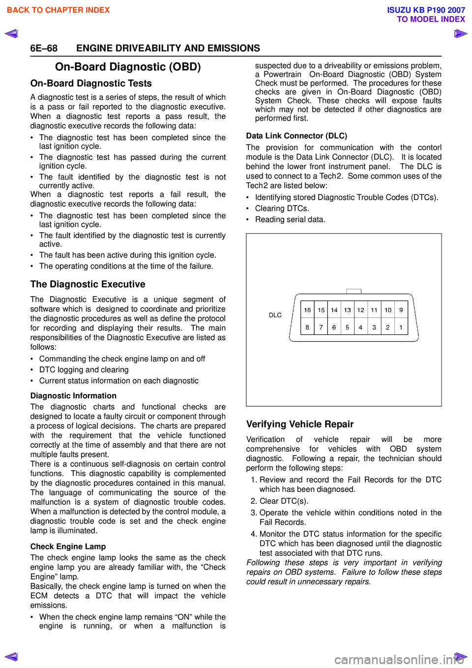
Data Link Connector (DLC)
The provision for communication with the contorl
module is the Data Link Connector (DLC). It is located
behind the lower front instrument panel. The DLC is
used to connect to a Tech 2. Some common uses of the
Tech 2 are listed below:
• Identifying stored Diagnostic Trouble Codes (DTCs).
• Clearing DTCs.
• Reading serial data.
Verifying Vehicle Repair
Verification of vehicle repair will be more
comprehensive for vehicles with OBD system
diagnostic. Following a repair, the technician should
perform the following steps:
1. Review and record the Fail Records for the DTC which has been diagnosed.
2. Clear DTC(s).
3. Operate the vehicle within conditions noted in the Fail Records.
4. Monitor the DTC status information for the specific DTC which has been diagnosed until the diagnostic
test associated with that DTC runs.
Following these steps is very important in verifying
repairs on OBD systems. Failure to follow these steps
could result in unnecessary repairs.
BACK TO CHAPTER INDEX
TO MODEL INDEX
ISUZU KB P190 2007
Page 2239 of 6020
ENGINE DRIVEABILITY AND EMISSIONS 6E–69
Reading Diagnostic Trouble Codes Using a
Te c h 2
The procedure for reading diagnostic trouble code(s) is
to used a diagnostic Tech 2. When reading DTC(s),
follow instructions supplied by Tech 2 manufacturer.
Clearing Diagnostic Trouble Codes
To clear Diagnostic Trouble Codes (DTCs), use the
Tech 2 “clear DTCs” or “clear information” function.
When clearing DTCs follow instructions supplied by the
Tech 2 manufacturer.
Diagnosis With Tech 2
If no codes are set:
•Refer to F1: Data Display and identify the electrical
faults that are not indicated by trouble code.
• Refer to “SYMPTOM DIAGNOSIS ”.
If codes are set: 1. Record all trouble codes displayed by Tech 2 and check id the codes are intermittent.
2. Clear the codes.
3. Drive the vehicle for a test to reproduce the faulty status.
4. Check trouble codes again using the Tech 2.
5. If no codes is displayed by test driving, the fault is intermittent. In this case, refer to “DIAGNOSIS
AIDS”.
6. If a code is present, refer to DTC Chart for diagnosis.
7. Check trouble codes again using the Tech 2.
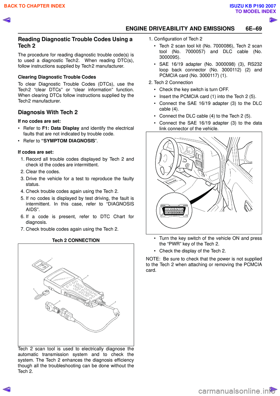
Tech 2 CONNECTION
Tech 2 scan tool is used to electrically diagnose the
automatic transmission system and to check the
system. The Tech 2 enhances the diagnosis efficiency
though all the troubleshooting can be done without the
Te c h 2 . 1. Configuration of Tech 2
• Tech 2 scan tool kit (No. 7000086), Tech 2 scan tool (No. 7000057) and DLC cable (No.
3000095).
• SAE 16/19 adapter (No. 3000098) (3), RS232 loop back connector (No. 3000112) (2) and
PCMCIA card (No. 3000117) (1).
2. Tech 2 Connection
• Check the key switch is turn OFF.
• Insert the PCMCIA card (1) into the Tech 2 (5).
• Connect the SAE 16/19 adapter (3) to the DLC cable (4).
• Connect the DLC cable (4) to the Tech 2 (5).
• Connect the SAE 16/19 adapter (3) to the data link connector of the vehicle.
• Turn the key switch of the vehicle ON and press the “PWR” key of the Tech 2.
• Check the display of the Tech 2.
NOTE: Be sure to check that the power is not supplied
to the Tech 2 when attaching or removing the PCMCIA
card.
BACK TO CHAPTER INDEX
TO MODEL INDEX
ISUZU KB P190 2007
Page 2241 of 6020
ENGINE DRIVEABILITY AND EMISSIONS 6E–71
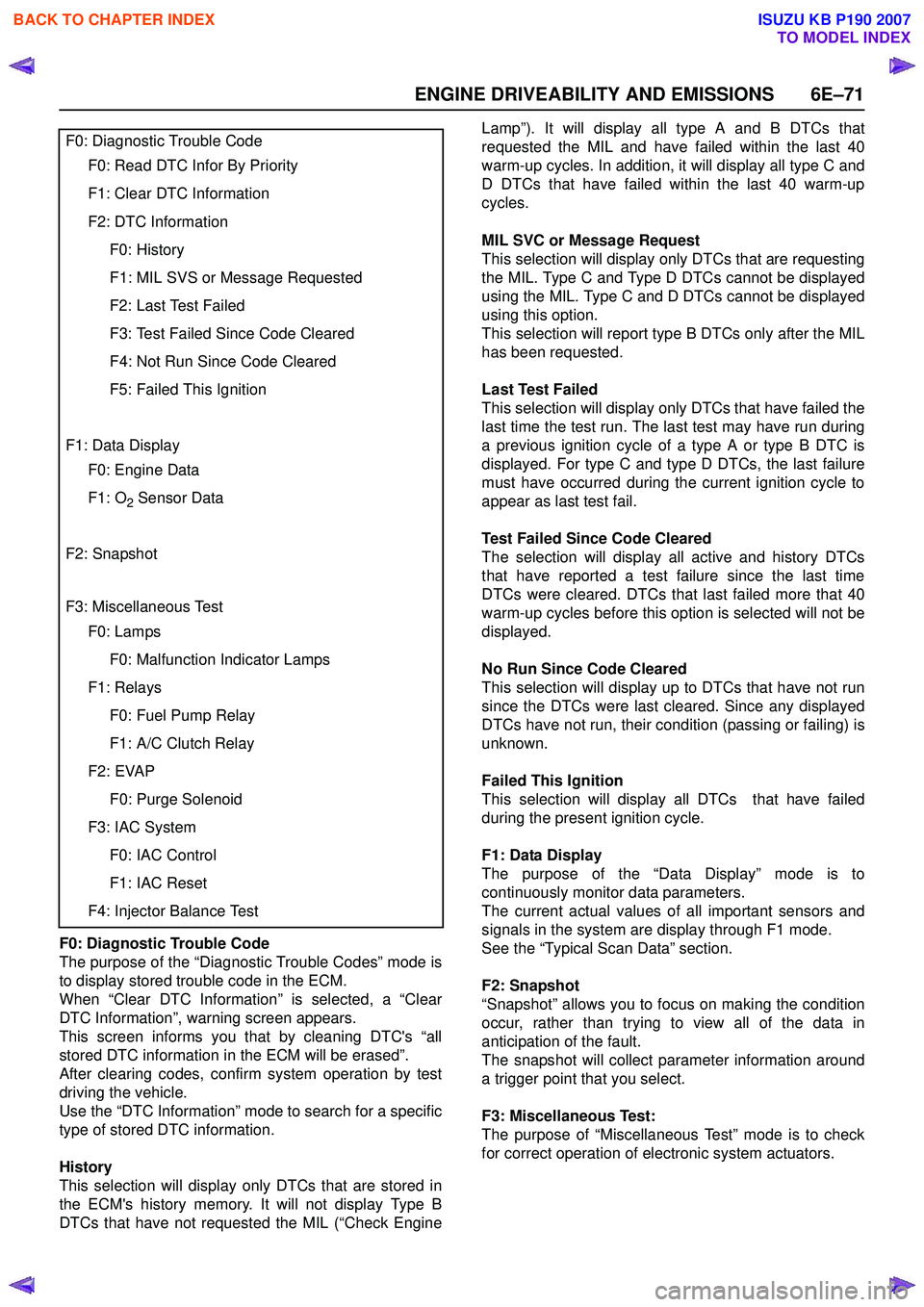
F0: Diagnostic Trouble Code
The purpose of the “Diagnostic Trouble Codes” mode is
to display stored trouble code in the ECM.
When “Clear DTC Information” is selected, a “Clear
DTC Information”, warning screen appears.
This screen informs you that by cleaning DTC's “all
stored DTC information in the ECM will be erased”.
After clearing codes, confirm system operation by test
driving the vehicle.
Use the “DTC Information” mode to search for a specific
type of stored DTC information.
History
This selection will display only DTCs that are stored in
the ECM's history memory. It will not display Type B
DTCs that have not requested the MIL (“Check Engine Lamp”). It will display all type A and B DTCs that
requested the MIL and have failed within the last 40
warm-up cycles. In addition, it will display all type C and
D DTCs that have failed within the last 40 warm-up
cycles.
MIL SVC or Message Request
This selection will display only DTCs that are requesting
the MIL. Type C and Type D DTCs cannot be displayed
using the MIL. Type C and D DTCs cannot be displayed
using this option.
This selection will report type B DTCs only after the MIL
has been requested.
Last Test Failed
This selection will display only DTCs that have failed the
last time the test run. The last test may have run during
a previous ignition cycle of a type A or type B DTC is
displayed. For type C and type D DTCs, the last failure
must have occurred during the current ignition cycle to
appear as last test fail.
Test Failed Since Code Cleared
The selection will display all active and history DTCs
that have reported a test failure since the last time
DTCs were cleared. DTCs that last failed more that 40
warm-up cycles before this option is selected will not be
displayed.
No Run Since Code Cleared
This selection will display up to DTCs that have not run
since the DTCs were last cleared. Since any displayed
DTCs have not run, their condition (passing or failing) is
unknown.
Failed This Ignition
This selection will display all DTCs that have failed
during the present ignition cycle.
F1: Data Display
The purpose of the “Data Display” mode is to
continuously monitor data parameters.
The current actual values of all important sensors and
signals in the system are display through F1 mode.
See the “Typical Scan Data” section.
F2: Snapshot
“Snapshot” allows you to focus on making the condition
occur, rather than trying to view all of the data in
anticipation of the fault.
The snapshot will collect parameter information around
a trigger point that you select.
F3: Miscellaneous Test:
The purpose of “Miscellaneous Test” mode is to check
for correct operation of electronic system actuators.
F0: Diagnostic Trouble Code
F0: Read DTC Infor By Priority
F1: Clear DTC Information
F2: DTC Information
F0: History
F1: MIL SVS or Message Requested
F2: Last Test Failed
F3: Test Failed Since Code Cleared
F4: Not Run Since Code Cleared
F5: Failed This Ignition
F1: Data Display
F0: Engine Data
F1: O2 Sensor Data
F2: Snapshot
F3: Miscellaneous Test
F0: Lamps
F0: Malfunction Indicator Lamps
F1: Relays
F0: Fuel Pump Relay
F1: A/C Clutch Relay
F2: EVAP
F0: Purge Solenoid
F3: IAC System
F0: IAC Control
F1: IAC Reset
F4: Injector Balance Test
BACK TO CHAPTER INDEX
TO MODEL INDEX
ISUZU KB P190 2007
Page 2242 of 6020
6E–72 ENGINE DRIVEABILITY AND EMISSIONS
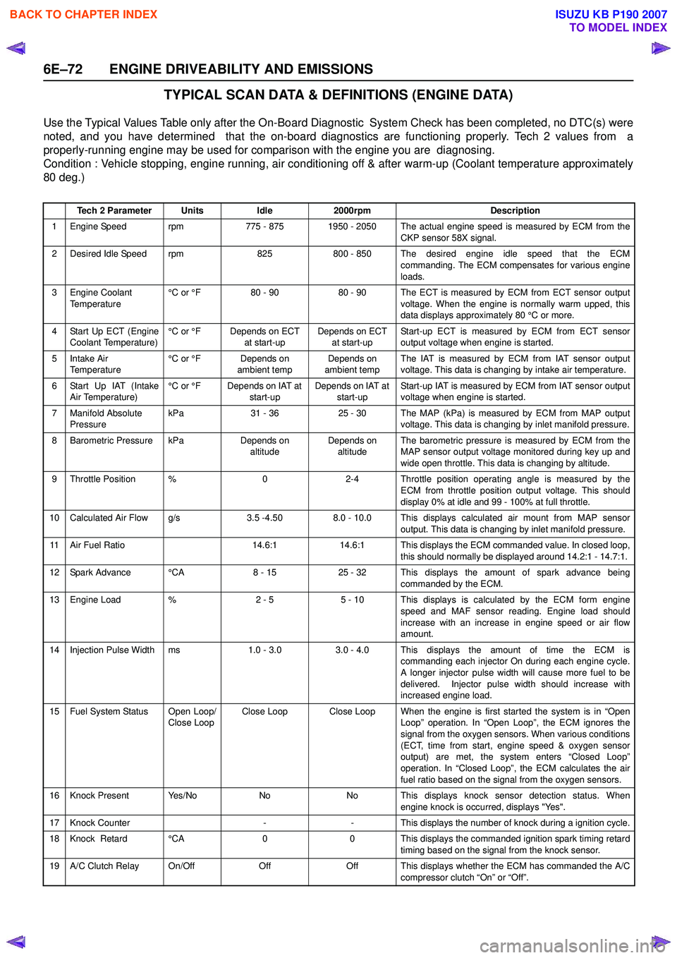
TYPICAL SCAN DATA & DEFINITIONS (ENGINE DATA)
Use the Typical Values Table only after the On-Board Diagnostic System Check has been completed, no DTC(s) were
noted, and you have determined that the on-board diagnostics are functioning properly. Tech 2 values from a
properly-running engine may be used for comparison with the engine you are diagnosing.
Condition : Vehicle stopping, engine running, air conditioning off & after warm-up (Coolant temperature approximately
80 deg.)
Tech 2 ParameterUnitsIdle2000rpmDescription
1 Engine Speed rpm775 - 8751950 - 2050 The actual engine speed is measured by ECM from the
CKP sensor 58X signal.
2 Desired Idle Speed rpm825800 - 850 The desired engine idle speed that the ECMcommanding. The ECM compensates for various engine
loads.
3 Engine Coolant Temperature °C or °F80 - 9080 - 90 The ECT is measured by ECM from ECT sensor output
voltage. When the engine is normally warm upped, this
data displays approximately 80 °C or more.
4 Start Up ECT (Engine Coolant Temperature) °C or °FDepends on ECT
at start-upDepends on ECT at start-up Start-up ECT is measured by ECM from ECT sensor
output voltage when engine is started.
5Intake Air
Temperature °C or °FDepends on
ambient tempDepends on
ambient temp The IAT is measured by ECM from IAT sensor output
voltage. This data is changing by intake air temperature.
6 Start Up IAT (Intake Air Temperature) °C or °FDepends on IAT at
start-upDepends on IAT at start-up Start-up IAT is measured by ECM from IAT sensor output
voltage when engine is started.
7 Manifold Absolute Pressure kPa31 - 3625 - 30The MAP (kPa) is measured by ECM from MAP output
voltage. This data is changing by inlet manifold pressure.
8 Barometric Pressure kPaDepends on altitudeDepends on altitude The barometric pressure is measured by ECM from the
MAP sensor output voltage monitored during key up and
wide open throttle. This data is changing by altitude.
9 Throttle Position %02-4 Throttle position operating angle is measured by the ECM from throttle position output voltage. This should
display 0% at idle and 99 - 100% at full throttle.
10 Calculated Air Flow g/s3.5 -4.508.0 - 10.0 This displays calculated air mount from MAP sensor output. This data is changing by inlet manifold pressure.
11 Air Fuel Ratio14.6:114.6:1 This displays the ECM commanded value. In closed loop,this should normally be displayed around 14.2:1 - 14.7:1.
12 Spark Advance °CA8 - 1525 - 32 This displays the amount of spark advance being commanded by the ECM.
13 Engine Load %2 - 55 - 10 This displays is calculated by the ECM form engine
speed and MAF sensor reading. Engine load should
increase with an increase in engine speed or air flow
amount.
14 Injection Pulse Width ms1.0 - 3.0 3.0 - 4.0 This displays the amount of time the ECM is commanding each injector On during each engine cycle.
A longer injector pulse width will cause more fuel to be
delivered. Injector pulse width should increase with
increased engine load.
15 Fuel System Status Open Loop/ Close LoopClose LoopClose Loop When the engine is first started the system is in “OpenLoop” operation. In “Open Loop”, the ECM ignores the
signal from the oxygen sensors. When various conditions
(ECT, time from start, engine speed & oxygen sensor
output) are met, the system enters “Closed Loop”
operation. In “Closed Loop”, the ECM calculates the air
fuel ratio based on the signal from the oxygen sensors.
16 Knock Present Yes/NoNoNo This displays knock sensor detection status. When engine knock is occurred, displays "Yes".
17 Knock Counter--This displays the number of knock during a ignition cycle.
18 Knock Retard °CA00 This displays the commanded ignition spark timing retard
timing based on the signal from the knock sensor.
19 A/C Clutch Relay On/OffOffOff This displays whether the ECM has commanded the A/C compressor clutch “On” or “Off”.
BACK TO CHAPTER INDEX
TO MODEL INDEX
ISUZU KB P190 2007
Page 2243 of 6020
ENGINE DRIVEABILITY AND EMISSIONS 6E–73
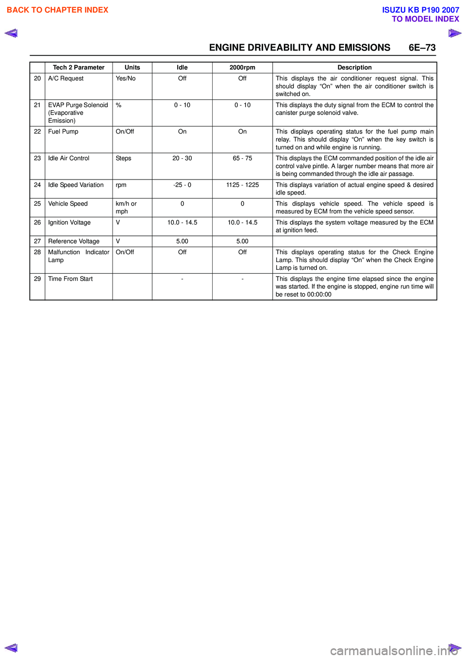
20 A/C Request Yes/NoOffOff This displays the air conditioner request signal. Thisshould display “On” when the air conditioner switch is
switched on.
21 EVAP Purge Solenoid (Evaporative
Emission) %0 - 100 - 10 This displays the duty signal from the ECM to control the
canister purge solenoid valve.
22 Fuel Pump On/OffOnOn This displays operating status for the fuel pump main
relay. This should display “On” when the key switch is
turned on and while engine is running.
23 Idle Air Control Steps20 - 3065 - 75 This displays the ECM commanded position of the idle air control valve pintle. A larger number means that more air
is being commanded through the idle air passage.
24 Idle Speed Variation rpm-25 - 01125 - 1225 This displays variation of actual engine speed & desired idle speed.
25 Vehicle Speed km/h or mph00This displays vehicle speed. The vehicle speed is
measured by ECM from the vehicle speed sensor.
26 Ignition Voltage V10.0 - 14.510.0 - 14.5 This displays the system voltage measured by the ECM at ignition feed.
27 Reference Voltage V5.005.00
28 Malfunction Indicator
Lamp On/OffOffOff This displays operating status for the Check Engine
Lamp. This should display “On” when the Check Engine
Lamp is turned on.
29Time From Start--This displays the engine time elapsed since the engine
was started. If the engine is stopped, engine run time will
be reset to 00:00:00
Tech 2 ParameterUnitsIdle2000rpmDescription
BACK TO CHAPTER INDEX
TO MODEL INDEX
ISUZU KB P190 2007
Page 2244 of 6020
6E–74 ENGINE DRIVEABILITY AND EMISSIONS
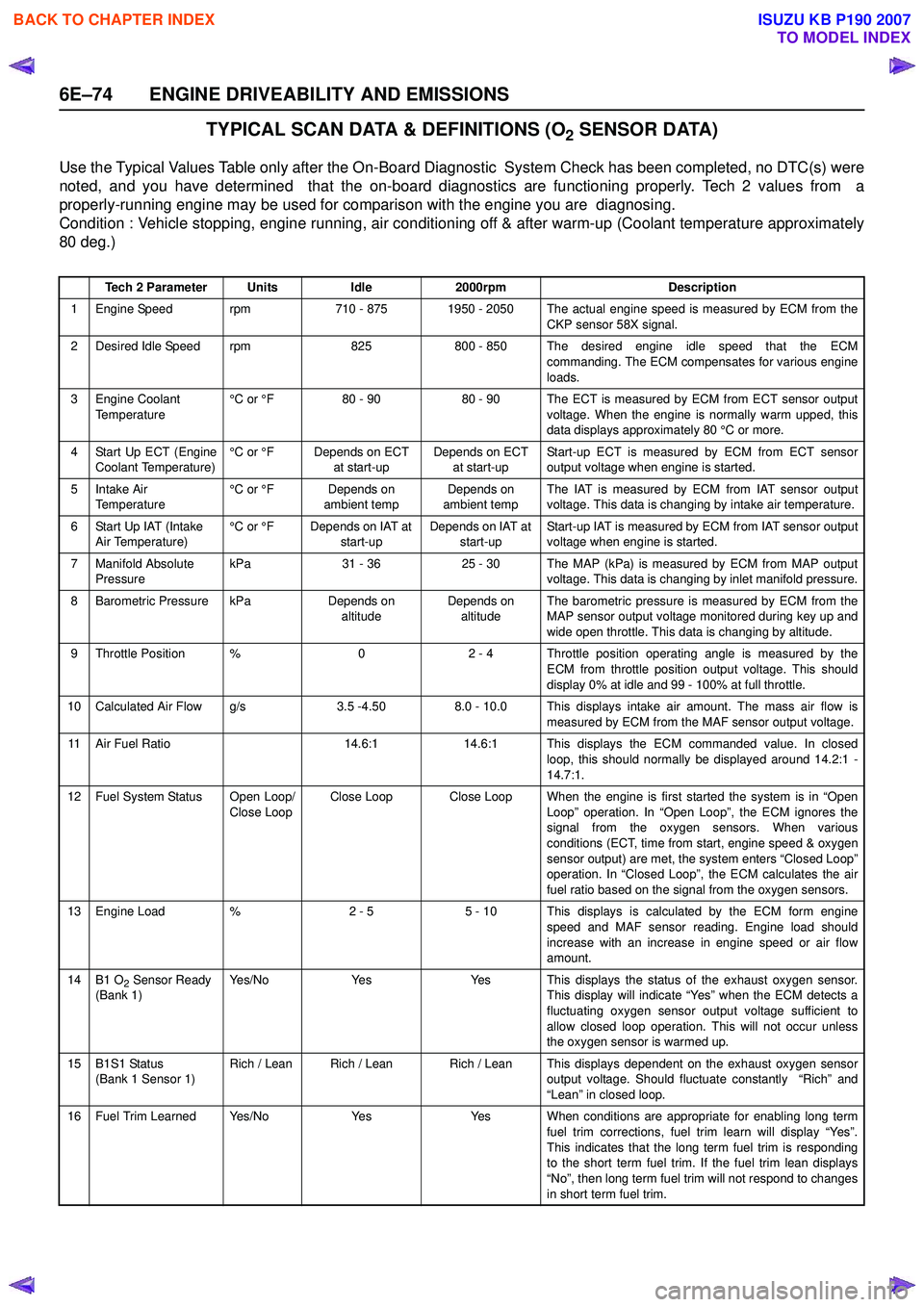
TYPICAL SCAN DATA & DEFINITIONS (O2 SENSOR DATA)
Use the Typical Values Table only after the On-Board Diagnostic System Check has been completed, no DTC(s) were
noted, and you have determined that the on-board diagnostics are functioning properly. Tech 2 values from a
properly-running engine may be used for comparison with the engine you are diagnosing.
Condition : Vehicle stopping, engine running, air conditioning off & after warm-up (Coolant temperature approximately
80 deg.)
Tech 2 ParameterUnitsIdle2000rpmDescription
1 Engine Speed rpm710 - 8751950 - 2050 The actual engine speed is measured by ECM from the
CKP sensor 58X signal.
2 Desired Idle Speed rpm825800 - 850 The desired engine idle speed that the ECMcommanding. The ECM compensates for various engine
loads.
3 Engine Coolant Temperature °C or °F80 - 9080 - 90 The ECT is measured by ECM from ECT sensor output
voltage. When the engine is normally warm upped, this
data displays approximately 80 °C or more.
4 Start Up ECT (Engine Coolant Temperature) °C or °FDepends on ECT
at start-upDepends on ECT at start-up Start-up ECT is measured by ECM from ECT sensor
output voltage when engine is started.
5Intake Air
Temperature °C or °FDepends on
ambient tempDepends on
ambient temp The IAT is measured by ECM from IAT sensor output
voltage. This data is changing by intake air temperature.
6 Start Up IAT (Intake Air Temperature) °C or °FDepends on IAT at
start-upDepends on IAT at start-up Start-up IAT is measured by ECM from IAT sensor output
voltage when engine is started.
7 Manifold Absolute Pressure kPa31 - 3625 - 30The MAP (kPa) is measured by ECM from MAP output
voltage. This data is changing by inlet manifold pressure.
8 Barometric Pressure kPaDepends on altitudeDepends on altitude The barometric pressure is measured by ECM from the
MAP sensor output voltage monitored during key up and
wide open throttle. This data is changing by altitude.
9 Throttle Position %02 - 4 Throttle position operating angle is measured by the ECM from throttle position output voltage. This should
display 0% at idle and 99 - 100% at full throttle.
10 Calculated Air Flow g/s3.5 -4.508.0 - 10.0 This displays intake air amount. The mass air flow is measured by ECM from the MAF sensor output voltage.
11 Air Fuel Ratio14.6:114.6:1 This displays the ECM commanded value. In closedloop, this should normally be displayed around 14.2:1 -
14.7:1.
12 Fuel System Status Open Loop/ Close LoopClose LoopClose Loop When the engine is first started the system is in “OpenLoop” operation. In “Open Loop”, the ECM ignores the
signal from the oxygen sensors. When various
conditions (ECT, time from start, engine speed & oxygen
sensor output) are met, the system enters “Closed Loop”
operation. In “Closed Loop”, the ECM calculates the air
fuel ratio based on the signal from the oxygen sensors.
13 Engine Load %2 - 55 - 10 This displays is calculated by the ECM form engine
speed and MAF sensor reading. Engine load should
increase with an increase in engine speed or air flow
amount.
14B1 O2 Sensor Ready
(Bank 1)Ye s / N oYe sYes This displays the status of the exhaust oxygen sensor. This display will indicate “Yes” when the ECM detects a
fluctuating oxygen sensor output voltage sufficient to
allow closed loop operation. This will not occur unless
the oxygen sensor is warmed up.
15B1S1 Status
(Bank 1 Sensor 1)Rich / LeanRich / LeanRich / Lean This displays dependent on the exhaust oxygen sensor output voltage. Should fluctuate constantly “Rich” and
“Lean” in closed loop.
16 Fuel Trim Learned Yes/NoYe sYes When conditions are appropriate for enabling long term fuel trim corrections, fuel trim learn will display “Yes”.
This indicates that the long term fuel trim is responding
to the short term fuel trim. If the fuel trim lean displays
“No”, then long term fuel trim will not respond to changes
in short term fuel trim.
BACK TO CHAPTER INDEX
TO MODEL INDEX
ISUZU KB P190 2007
Page 2245 of 6020
ENGINE DRIVEABILITY AND EMISSIONS 6E–75
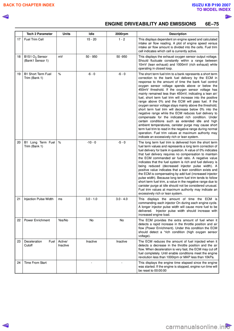
17 Fuel Trim Cell15 - 201 - 2 This displays dependent on engine speed and calculatedintake air flow reading. A plot of engine speed versus
intake air flow amount is divided into the cells. Fuel trim
cell indicates which cell is currently active.
18B1S1 O2 Sensor
(Bank1 Sensor 1)mV50 - 95050 -950 This displays the exhaust oxygen sensor output voltage. Should fluctuate constantly within a range between
10mV (lean exhaust) and 1000mV (rich exhaust) while
operating in closed loop.
19B1 Short Term Fuel
Trim (Bank 1)%-6 - 0-6 - 0 The short term fuel trim to a bank represents a short term correction to the bank fuel delivery by the ECM in
response to the amount of time the bank fuel control
oxygen sensor voltage spends above or below the
450mV threshold. If the oxygen sensor voltage has
mainly remained less than 450mV, indicating a lean air/
fuel, short term fuel trim will increase into the positive
range above 0% and the ECM will pass fuel. If the
oxygen sensor voltage stays mainly above the threshold,
short term fuel trim will decrease below 0% into the
negative range while the ECM reduces fuel delivery to
compensate for the indicated rich condition. Under
certain conditions such as extended idle and high
ambient temperatures, canister purge may cause short
term fuel trim to read in the negative range during normal
operation. Fuel trim values at maximum authority may
indicate an excessively rich or lean system.
20B1 Long Term Fuel
Trim (Bank 1)%-10 - 0-5 - 0 The long term fuel trim is delivered from the short term fuel term values and represents a long term correction of
fuel delivery for bank in question. A value of 0% indicates
that fuel delivery requires no compensation to maintain
the ECM commanded air fuel ratio. A negative value
indicates that the fuel system is rich and fuel delivery is
being reduced (decreased injector pulse width). A
positive value indicates that a lean condition exists and
the ECM is compensating by add fuel (increased injector
pulse width). Because long term fuel trim tends to follow
short term fuel trim, a value in the negative range due to
canister purge at idle should not be considered unusual.
Fuel trim values at maximum authority may indicate an
excessively rich or lean system.
21Injection Pulse Widthms3.0 - 1.03.0 - 4.0 This displays the amount of time the ECM is commanding each injector On during each engine cycle.
A longer injector pulse width will cause more fuel to be
delivered. Injector pulse width should increase with
increased engine load.
22Power EnrichmentYe s / N oNoNo The ECM provides the extra amount of fuel when it detects a rapid increase in the throttle position and air
flow (Power Enrichment). Under this condition the ECM
should detect a “rich condition (high oxygen sensor
voltage).
23Deceleration Fuel
Cutoff Active/
InactiveInactiveInactiveThe ECM reduces the amount of fuel injected when it
detects a decrease in the throttle position and the air
flow. When deceleration is very fast, the ECM may cut off
fuel completely. Until enable conditions meet the engine
revolution less than 1000rpm or MAP less than 10kPa.
24Time From Start--This displays the engine time elapsed since the engine
was started. If the engine is stopped, engine run time will
be reset to 00:00:00
Tech 2 ParameterUnitsIdle2000rpmDescription
BACK TO CHAPTER INDEX
TO MODEL INDEX
ISUZU KB P190 2007