display ISUZU KB P190 2007 Workshop Owner's Manual
[x] Cancel search | Manufacturer: ISUZU, Model Year: 2007, Model line: KB P190, Model: ISUZU KB P190 2007Pages: 6020, PDF Size: 70.23 MB
Page 668 of 6020

BRAKE CONTROL SYSTEM 5A-75
Step Action
Value(s) Yes No
3 1. Ignition “ON”, engine “OFF”.
2. Select “Display DTCs” with the Tech 2. Note: Perform the various tests (actuator test, test
run, brake test, etc.) then observe the DTC with a
Tech 2.
Are any DTCs stored? - Go to Step 4 Verify repair
4 Replace EHCU.
Note: Check the EHCU type for specification, when
the EHCU is replaced.
(Specification ; 2W D model or 4W D model)
Is the action complete? - Verify repair -
BACK TO CHAPTER INDEX
TO MODEL INDEX
ISUZU KB P190 2007
Page 670 of 6020

BRAKE CONTROL SYSTEM 5A-77
3 1. Ignition “ON”, engine “OFF”.
2. Select “Display DTCs” with the Tech 2. Note: Perform the various tests (actuator test, test
run, brake test, etc.) then observe the DTC with a
Tech 2.
Are any DTCs stored? - Go to Step 4 Verify repair
4 Replace EHCU.
Note: Check the EHCU type for specification, when
the EHCU is replaced.
(Specification ; 2W D model or 4W D model)
Is the action complete? - Verify repair -
BACK TO CHAPTER INDEX
TO MODEL INDEX
ISUZU KB P190 2007
Page 672 of 6020

BRAKE CONTROL SYSTEM 5A-79
Step Action
Value(s) Yes No
6 1. Remove the G sensor.
2. Reconnect G sensor and EHCU
3. Install the Tech 2.
4. Ignition "ON", engine "OFF".
5. Observe the G sensor reading on Tech 2. If G sensor inclines, reading voltage will change.
Is the reading voltage between specified values? 1.0 - 4.0V Go to Step 7 Go to Step 8
7 1. Ignition "OFF". 2. Install the G sensor.
3. Install the Tech 2.
4. Ignition "ON", engine "OFF".
5. Select "Display DTCs" with the Tech 2. Are any DTCs stored? - Go to Step 8 Verify repair
8 1. Replace G sensor.
2. Select "Display DTCs" with the Tech 2. Note: Perform the various tests (actuator test, test
run, brake test, etc.) then observe the DTC with a
Tech 2.
Are any DTCs stored? - Go to Step 9 Verify repair
9 Replace EHCU.
Note: Check the EHCU type for specification, when
the EHCU is replaced.
(Specification ; 2W D model or 4W D model)
Is the action complete? - Verify repair -
BACK TO CHAPTER INDEX
TO MODEL INDEX
ISUZU KB P190 2007
Page 674 of 6020

BRAKE CONTROL SYSTEM 5A-81
Step Action
Value(s) Yes No
5 1. Check the power supply circuit.
(Check circuit for an open, short to ground, or short
to voltage.)
2. If a problem is found, repair as necessary. W as a problem found? - Verify repair Go to Step 6
6 1. Ignition “ON”, engine “OFF”.
2. Select “Display DTCs” with the Tech 2. Note: Perform the various tests (actuator test, test
run, brake test, etc.) then observe the DTC with a
Tech 2.
Are any DTCs stored? - Go to Step 7 Verify repair
7 Replace EHCU.
Note: Check the EHCU type for specification, when
the EHCU is replaced.
(Specification ; 2W D model or 4W D model)
Is the action complete? - Verify repair -
BACK TO CHAPTER INDEX
TO MODEL INDEX
ISUZU KB P190 2007
Page 676 of 6020

BRAKE CONTROL SYSTEM 5A-83
Step Action
Value(s) Yes No
5 1. Ignition "OFF".
2. Connect 2-4W D control unit.
3. Disconnect EHCU.
4. Ignition "ON," engine "OFF."
5. Install the high impedance digital multimeter.
6. Check the transfer (2-4W D control unit) signal value. (Battery voltage is more than 10V.)
W as the value normal? Transfer 2W D
Mode: 8.3Hz (± 15%)
Transfer 4W D Mode: 4.2Hz (± 15%) Go to Step 7 Go to Step 6
6 Replace 2-4W D control unit.
Is the action complete?
- Go to Step 7 -
7 1. Ignition “ON”, engine “OFF”. 2. Select “Display DTCs” with the Tech 2. Note: Perform the various tests (actuator test, test
run, brake test, etc.) then observe the DTC with a
Tech 2.
Are any DTCs stored? - Go to Step 8 Verify repair
8 Replace EHCU.
Note: Check the EHCU type for specification, when
the EHCU is replaced.
(Specification ; 2W D model or 4W D model)
Is the action complete? - Verify repair -
BACK TO CHAPTER INDEX
TO MODEL INDEX
ISUZU KB P190 2007
Page 678 of 6020

BRAKE CONTROL SYSTEM 5A-85
Step Action Value(s) Yes No
4 1. Ignition "OFF".
2. Check for a poor condition at the EHCU harness connector.
3. Check the EHCU circuit for an open, short to ground, or short to voltage. Also, check the EHCU
ignition feed circuit for an open or short to ground
and the EHCU ground circuit for an open or short to
voltage.
4. If a problem is found, repair as necessary. W as a problem found? - Verify repair Go to Step 9
5 1. Ignition "OFF", disconnect the EHCU and G sensor.
2. Check the circuit between EHCU and G sensor. (short to ground, or short to voltage.)
3. If a problem is found, repair as necessary. W as a problem found? - Verify repair
Go to Step 6 Go to Step 6
6 1. Remove the G sensor. 2. Reconnect G sensor and EHCU
3. Install the Tech 2.
4. Ignition "ON", engine "OFF".
5. Observe the G sensor reading on Tech 2. If G sensor inclines, reading voltage will change.
Is the reading voltage between specified values? 1.0 – 4.0 V Go to Step 7 Go to Step 8
7 1. Ignition "OFF". 2. Install the G sensor.
3. Install the Tech 2.
4. Ignition "ON", engine "OFF".
5. Select "Display DTCs" with the Tech 2. Are any DTCs stored? - Go to Step 8 Verify repair
8 1. Replace G sensor.
2. Select "Display DTCs" with the Tech 2. Note: Perform the various tests (actuator test, test
run, brake test, etc.) then observe the DTC with a
Tech 2.
Are any DTCs stored? - Go to Step 9 Verify repair
9 Replace EHCU.
Note: Check the EHCU type for specification, when
the EHCU is replaced.
(Specification ; 2W D model or 4W D model)
Is the action complete? - Verify repair -
BACK TO CHAPTER INDEX
TO MODEL INDEX
ISUZU KB P190 2007
Page 1065 of 6020

Engine Control System (4JH1) 6E-31
Diagnostic Starting Point - Engine Controls
Begin the system diagnosis with Diagnostic System
Check - Engine Controls. The Diagnostic System Check
- Engine Controls will provide the following information:
• The identification of the control modules which
command the system.
• The ability of the control modules to communicate
through the serial data circuit.
• The identification of any stored diagnostic trouble
codes (DTCs) and the their statuses.
The use of the Diagnostic System Check - Engine
Controls will identify the correct procedure fo
r
diagnosing the system and where the procedure is
located.
Important:
Engine Control System Check Sheet must be used to
verify the complaint vehicle, you need to know the
correct (normal) operating behavior of the system and
verify that the customer complaint is a valid failure o
f
the system.
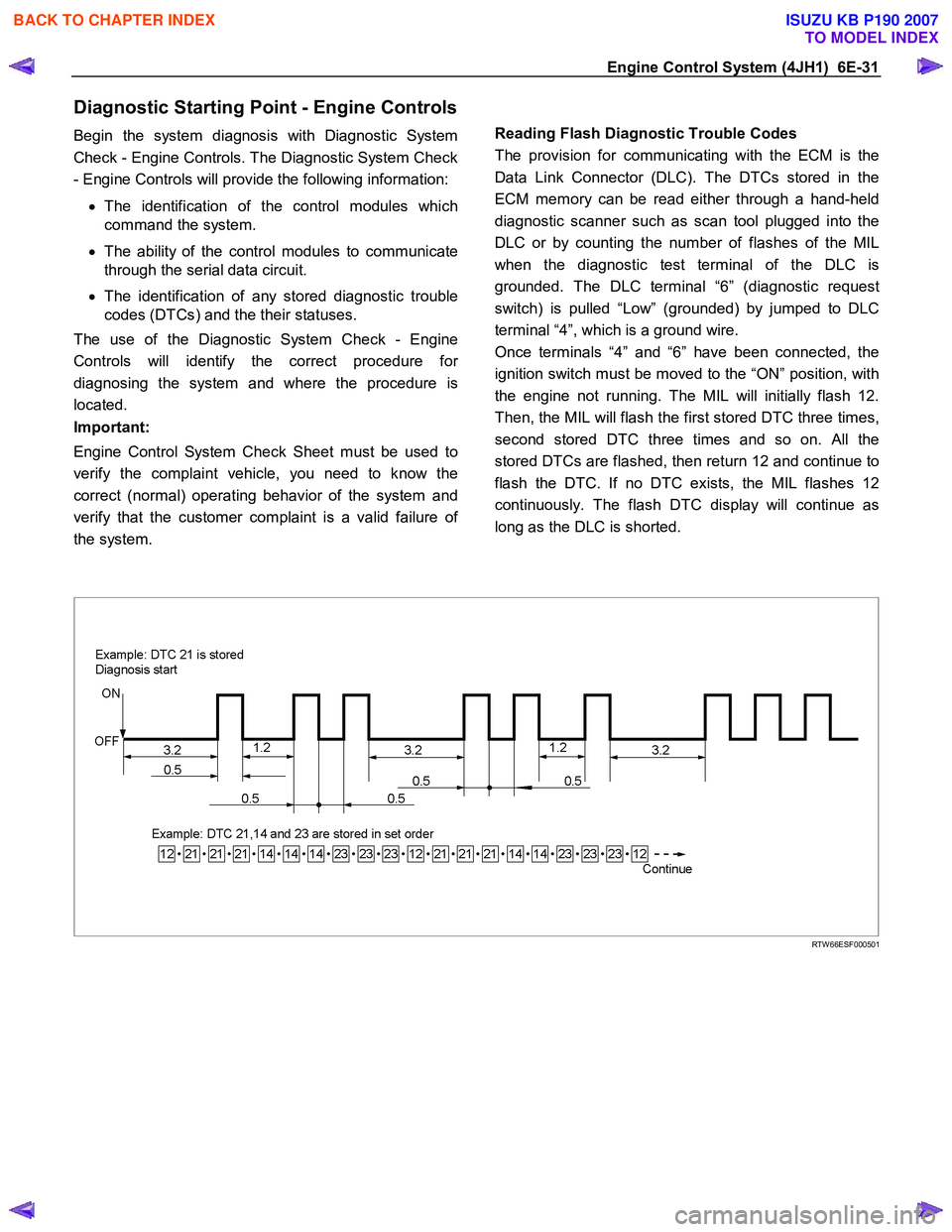
Reading Flash Diagnostic Trouble Codes
The provision for communicating with the ECM is the
Data Link Connector (DLC). The DTCs stored in the
ECM memory can be read either through a hand-held
diagnostic scanner such as scan tool plugged into the
DLC or by counting the number of flashes of the MIL
when the diagnostic test terminal of the DLC is
grounded. The DLC terminal “6” (diagnostic request
switch) is pulled “Low” (grounded) by jumped to DLC
terminal “4”, which is a ground wire.
Once terminals “4” and “6” have been connected, the
ignition switch must be moved to the “ON” position, with
the engine not running. The MIL will initially flash 12.
Then, the MIL will flash the first stored DTC three times,
second stored DTC three times and so on. All the
stored DTCs are flashed, then return 12 and continue to
flash the DTC. If no DTC exists, the MIL flashes 12
continuously. The flash DTC display will continue as
long as the DLC is shorted.
RTW 66ESF000501
BACK TO CHAPTER INDEX
TO MODEL INDEX
ISUZU KB P190 2007
Page 1068 of 6020

6E-34 Engine Control System (4JH1)
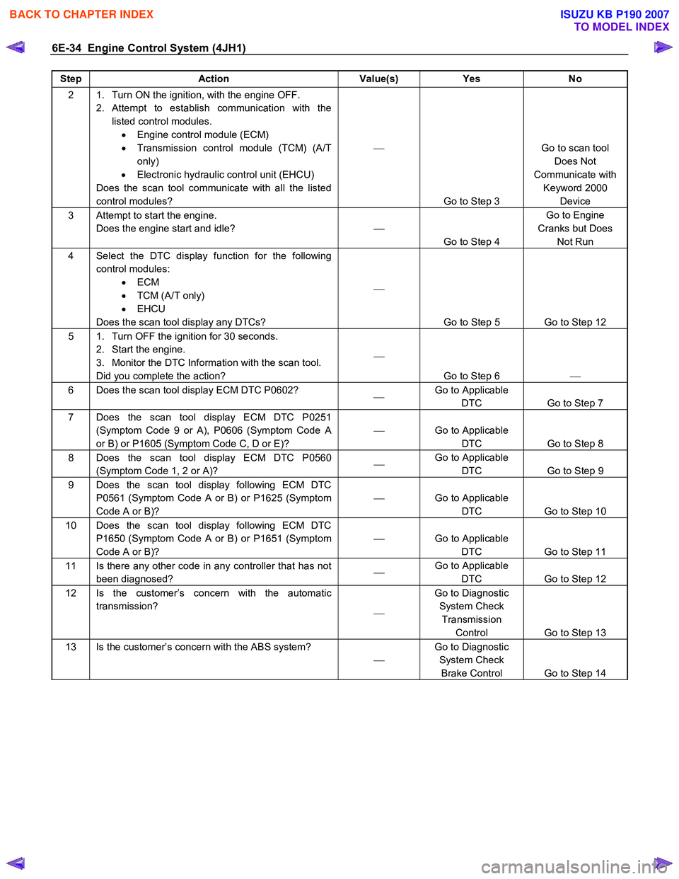
Step Action Value(s) Yes No
2 1. Turn ON the ignition, with the engine OFF.
2. Attempt to establish communication with the listed control modules. • Engine control module (ECM)
• Transmission control module (TCM) (A/T
only)
• Electronic hydraulic control unit (EHCU)
Does the scan tool communicate with all the listed
control modules?
Go to Step 3 Go to scan tool
Does Not
Communicate with Keyword 2000 Device
3 Attempt to start the engine. Does the engine start and idle?
Go to Step 4 Go to Engine
Cranks but Does Not Run
4 Select the DTC display function for the following control modules: • ECM
• TCM (A/T only)
• EHCU
Does the scan tool display any DTCs?
Go to Step 5 Go to Step 12
5 1. Turn OFF the ignition for 30 seconds. 2. Start the engine.
3. Monitor the DTC Information with the scan tool.
Did you complete the action?
Go to Step 6
6 Does the scan tool display ECM DTC P0602?
Go to Applicable
DTC Go to Step 7
7 Does the scan tool display ECM DTC P0251 (Symptom Code 9 or A), P0606 (Symptom Code A
or B) or P1605 (Symptom Code C, D or E)?
Go to Applicable
DTC Go to Step 8
8 Does the scan tool display ECM DTC P0560 (Symptom Code 1, 2 or A)?
Go to Applicable
DTC Go to Step 9
9 Does the scan tool display following ECM DTC
P0561 (Symptom Code A or B) or P1625 (Symptom
Code A or B)?
Go to Applicable
DTC Go to Step 10
10 Does the scan tool display following ECM DTC P1650 (Symptom Code A or B) or P1651 (Symptom
Code A or B)?
Go to Applicable
DTC Go to Step 11
11 Is there any other code in any controller that has not
been diagnosed?
Go to Applicable
DTC Go to Step 12
12 Is the customer’s concern with the automatic
transmission? Go to Diagnostic
System Check Transmission Control Go to Step 13
13 Is the customer’s concern with the ABS system?
Go to Diagnostic
System Check Brake Control Go to Step 14
BACK TO CHAPTER INDEX
TO MODEL INDEX
ISUZU KB P190 2007
Page 1070 of 6020

6E-36 Engine Control System (4JH1)
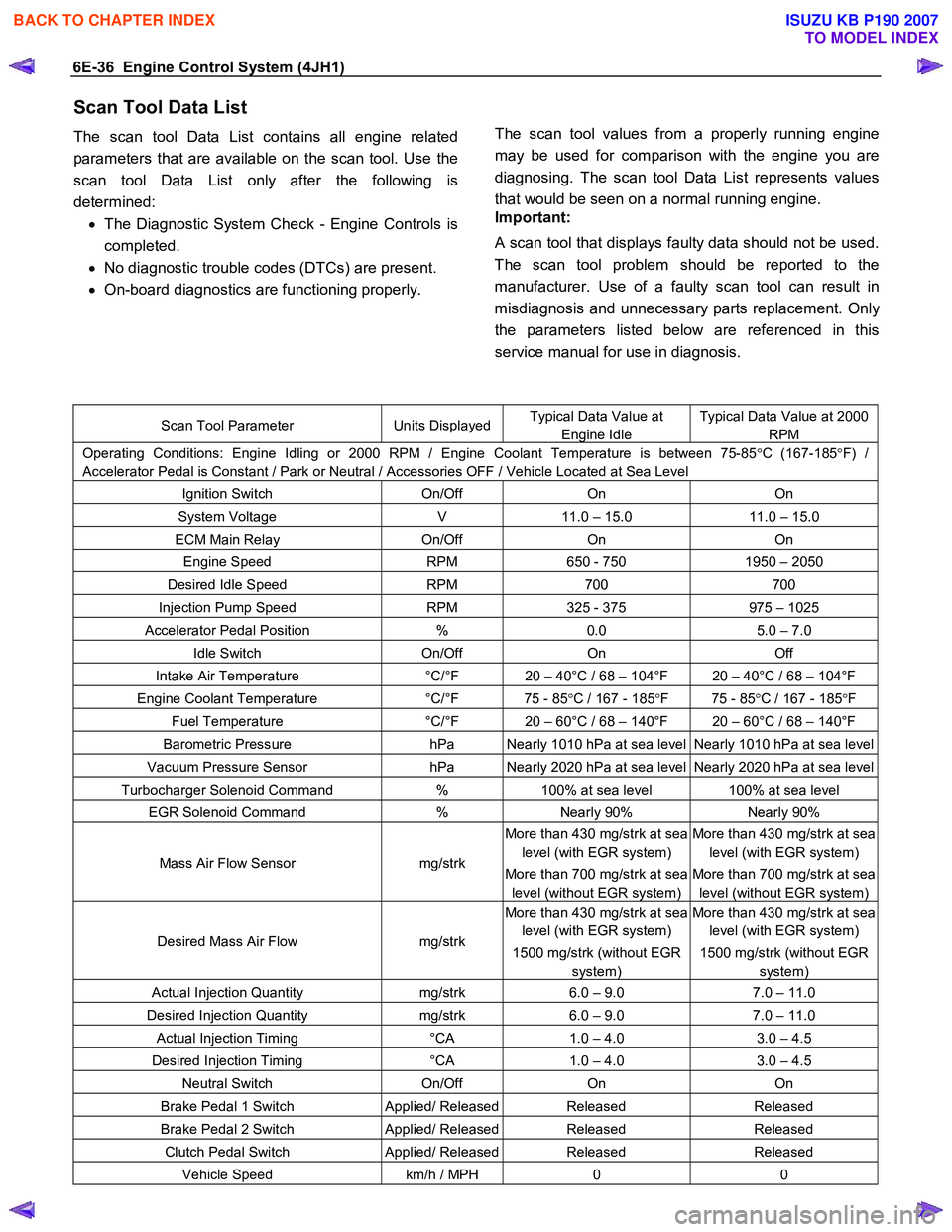
Scan Tool Data List
The scan tool Data List contains all engine related
parameters that are available on the scan tool. Use the
scan tool Data List only after the following is
determined: • The Diagnostic System Check - Engine Controls is
completed.
• No diagnostic trouble codes (DTCs) are present.
• On-board diagnostics are functioning properly.
The scan tool values from a properly running engine
may be used for comparison with the engine you are
diagnosing. The scan tool Data List represents values
that would be seen on a normal running engine.
Important:
A scan tool that displays faulty data should not be used.
The scan tool problem should be reported to the
manufacturer. Use of a faulty scan tool can result in
misdiagnosis and unnecessary parts replacement. Onl
y
the parameters listed below are referenced in this
service manual for use in diagnosis.
Scan Tool Parameter Units DisplayedTypical Data Value at
Engine Idle
Typical Data Value at 2000
RPM
Operating Conditions: Engine Idling or 2000 RPM / Engine Coolant Temperature is between 75-85 °C (167-185 °F) /
Accelerator Pedal is Constant / Park or Neutral / Accessories OFF / Vehicle Located at Sea Level
Ignition Switch On/Off On On
System Voltage V 11.0 – 15.0 11.0 – 15.0
ECM Main Relay On/Off On On
Engine Speed RPM 650 - 750 1950 – 2050
Desired Idle Speed RPM 700 700
Injection Pump Speed RPM 325 - 375 975 – 1025
Accelerator Pedal Position % 0.0 5.0 – 7.0
Idle Switch On/Off On Off
Intake Air Temperature °C/°F 20 – 40°C / 68 – 104°F 20 – 40°C / 68 – 104°F
Engine Coolant Temperature °C/°F 75 - 85 °C / 167 - 185 °F 75 - 85 °C / 167 - 185 °F
Fuel Temperature °C/°F 20 – 60°C / 68 – 140°F 20 – 60°C / 68 – 140°F
Barometric Pressure hPa Nearly 1010 hPa at sea level Nearly 1010 hPa at sea level
Vacuum Pressure Sensor hPa Nearly 2020 hPa at sea level Nearly 2020 hPa at sea level
Turbocharger Solenoid Command % 100% at sea level 100% at sea level
EGR Solenoid Command % Nearly 90% Nearly 90%
Mass Air Flow Sensor mg/strk
More than 430 mg/strk at sea
level (with EGR system)
More than 700 mg/strk at sea
level (without EGR system)
More than 430 mg/strk at sea
level (with EGR system)
More than 700 mg/strk at sea
level (without EGR system)
Desired Mass Air Flow mg/strk
More than 430 mg/strk at sea
level (with EGR system)
1500 mg/strk (without EGR
system)
More than 430 mg/strk at sea
level (with EGR system)
1500 mg/strk (without EGR
system)
Actual Injection Quantity mg/strk 6.0 – 9.0 7.0 – 11.0
Desired Injection Quantity mg/strk 6.0 – 9.0 7.0 – 11.0
Actual Injection Timing °CA 1.0 – 4.0 3.0 – 4.5
Desired Injection Timing °CA 1.0 – 4.0 3.0 – 4.5
Neutral Switch On/Off On On
Brake Pedal 1 Switch Applied/ ReleasedReleased Released
Brake Pedal 2 Switch Applied/ ReleasedReleased Released
Clutch Pedal Switch Applied/ ReleasedReleased Released
Vehicle Speed km/h / MPH 0 0
BACK TO CHAPTER INDEX
TO MODEL INDEX
ISUZU KB P190 2007
Page 1071 of 6020

Engine Control System (4JH1) 6E-37
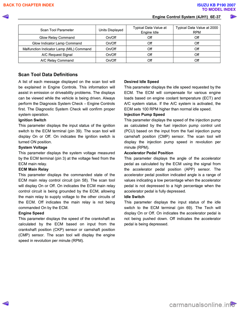
Scan Tool Parameter Units DisplayedTypical Data Value at
Engine Idle
Typical Data Value at 2000
RPM
Glow Relay Command On/Off Off Off
Glow Indicator Lamp Command On/Off Off Off
Malfunction Indicator Lamp (MIL) Command On/Off Off Off
A/C Request Signal On/Off Off Off
A/C Relay Command On/Off Off Off
Scan Tool Data Definitions
A list of each message displayed on the scan tool will
be explained in Engine Controls. This information will
assist in emission or driveability problems. The displays
can be viewed while the vehicle is being driven. Always
perform the Diagnosis System Check – Engine Controls
first. The Diagnostic System Check will confirm prope
r
system operation.
Ignition Switch
This parameter displays the input status of the ignition
switch to the ECM terminal (pin 39). The scan tool will
display On or Off. On indicates the ignition switch is
turned ON position.
System Voltage
This parameter displays the system voltage measured
by the ECM terminal (pin 3) at the voltage feed from the
ECM main relay.
ECM Main Relay
This parameter displays the commanded state of the
ECM main relay control circuit (pin 58). The scan tool
will display On or Off. On indicates the ECM main rela
y
control circuit is being grounded by the ECM, allowing
the main relay to supply voltage to the other circuits o
f
the ECM. Off indicates the main relay is not being
commanded On by the ECM.
Engine Speed
This parameter displays the speed of the crankshaft as
calculated by the ECM based on input from the
crankshaft position (CKP) sensor or camshaft position
(CMP) sensor. The scan tool will display the engine
speed in revolution per minute (RPM).
Desired Idle Speed
This parameter displays the idle speed requested by the
ECM. The ECM will compensate for various engine
loads based on engine coolant temperature (ECT) and
A/C system status. If the A/C system is activated, the
ECM sets 100 RPM higher than normal idle speed.
Injection Pump Speed
This parameter displays the speed of the injection pump
as calculated by the fuel injection pump control unit
(PCU) based on the input from the fuel injection pump
camshaft position (CMP) sensor. The scan tool will
display the injection pump speed in revolution pe
r
minute (RPM).
Accelerator Pedal Position
This parameter displays the angle of the accelerato
r
pedal as calculated by the ECM using the signal from
the accelerator pedal position (APP) sensor. The
accelerator pedal position indicated angle is a range o
f
values indicating a low percentage when the accelerator
pedal is not depressed to a high percentage when the
accelerator pedal is fully depressed.
Idle Switch
This parameter displays the input status of the idle
switch to the ECM terminal (pin 69). The Tech will
display On or Off. On indicates the accelerator pedal is
not being pushed down. Off indicates the accelerato
r
pedal is being depressed.
BACK TO CHAPTER INDEX
TO MODEL INDEX
ISUZU KB P190 2007