lock ISUZU KB P190 2007 Workshop Repair Manual
[x] Cancel search | Manufacturer: ISUZU, Model Year: 2007, Model line: KB P190, Model: ISUZU KB P190 2007Pages: 6020, PDF Size: 70.23 MB
Page 4607 of 6020
MANUAL TRANSMISSION 7B1-1
SECTION 7B1
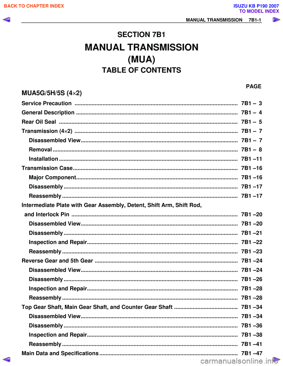
MANUAL TRANSMISSION
(MUA)
TABLE OF CONTENTS
PAGE
MUA5G/5H/5S (4 ×
××
×
2)
Service Precaution ......................................................................................................... 7B 1 – 3
General Description ........................................................................................................ 7B 1 – 4
Rear Oil Seal ................................................................................................................. .. 7B1 – 5
Transmission (4 ×
××
×
2) ......................................................................................................... 7B1 – 7
Disassembled View..................................................................................................... 7B1 – 7
Removal ....................................................................................................................... 7B1 – 8
Installation ................................................................................................................... 7B1 –11
Transmission Case .......................................................................................................... 7B1 –16
Major Component........................................................................................................ 7B1 –16
Disassembly ................................................................................................................ 7B1 –17
Reassembly ................................................................................................................. 7B1 –17
Intermediate Plate with Gear Assembly, Detent, Shift Arm, Shift Rod,
and Interlock Pin ........................................................................................................... 7B1 –20
Disassembled View..................................................................................................... 7B1 –20
Disassembly ................................................................................................................ 7B1 –21
Inspection and Repair................................................................................................. 7B1 –22
Reassembly ................................................................................................................. 7B1 –23
Reverse Gear and 5th Gear ............................................................................................ 7B1 –24 Disassembled View..................................................................................................... 7B1 –24
Disassembly ................................................................................................................ 7B1 –26
Inspection and Repair................................................................................................. 7B1 –28
Reassembly ................................................................................................................. 7B1 –28
Top Gear Shaft, Main Gear Shaft, and Counter Gear Shaft ......................................... 7B1 –34 Disassembled View..................................................................................................... 7B1 –34
Disassembly ................................................................................................................ 7B1 –36
Inspection and Repair................................................................................................. 7B1 –38
Reassembly ................................................................................................................. 7B1 –41
Main Data and Specifications ......................................................................................... 7B1 –47
BACK TO CHAPTER INDEX
TO MODEL INDEX
ISUZU KB P190 2007
Page 4608 of 6020
7B1-2 MANUAL TRANSMISSION
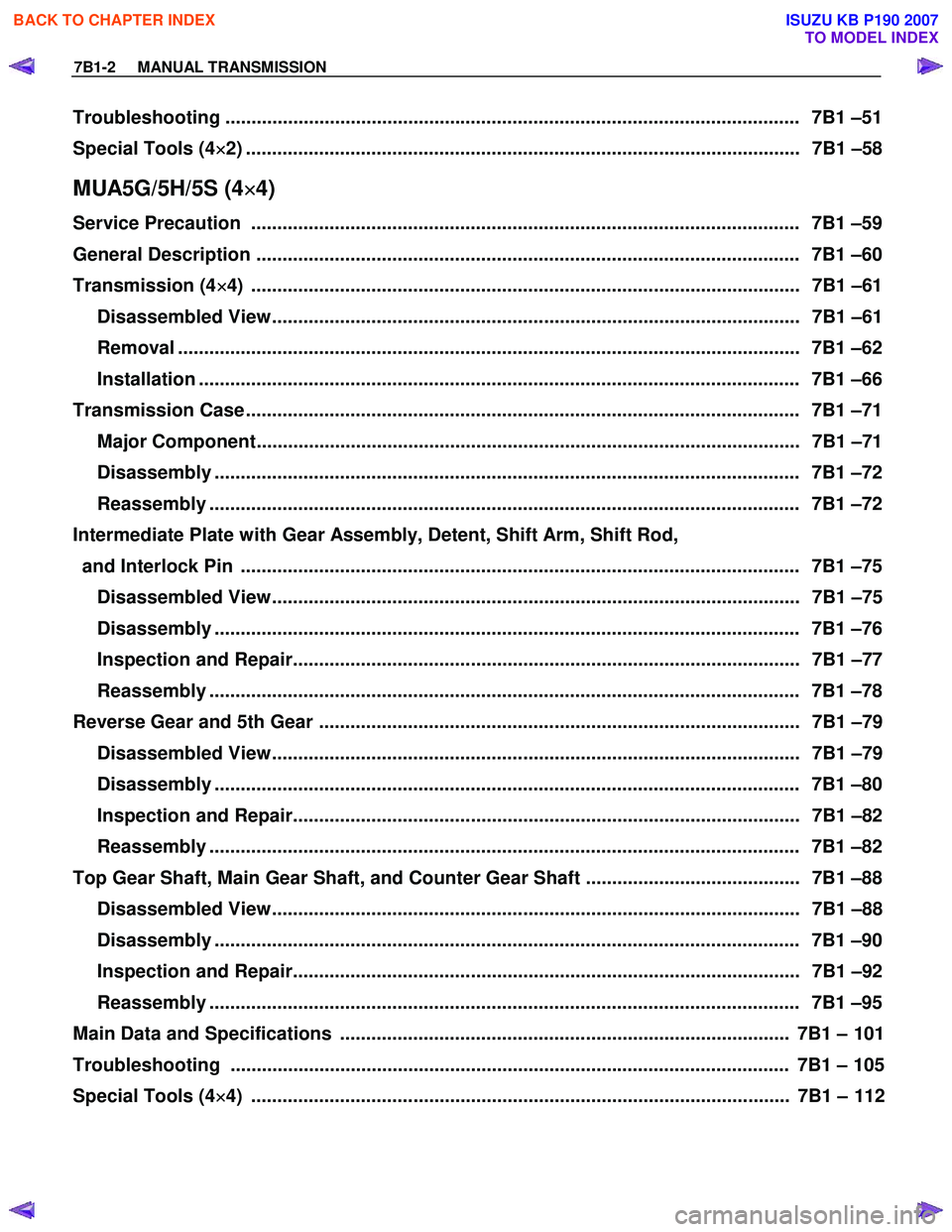
Troubleshooting .............................................................................................................. 7 B1 –51
Special Tools (4 ×
××
×
2) .......................................................................................................... 7B1 –58
MUA5G/5H/5S (4×
××
×
4)
Service Precaution ......................................................................................................... 7B 1 –59
General Description ........................................................................................................ 7B 1 –60
Transmission (4 ×
××
×
4) ......................................................................................................... 7B1 –61
Disassembled View..................................................................................................... 7B1 –61
Removal ....................................................................................................................... 7B1 –62
Installation ................................................................................................................... 7B1 –66
Transmission Case .......................................................................................................... 7B1 –71
Major Component........................................................................................................ 7B1 –71
Disassembly ................................................................................................................ 7B1 –72
Reassembly ................................................................................................................. 7B1 –72
Intermediate Plate with Gear Assembly, Detent, Shift Arm, Shift Rod,
and Interlock Pin ........................................................................................................... 7B1 –75
Disassembled View..................................................................................................... 7B1 –75
Disassembly ................................................................................................................ 7B1 –76
Inspection and Repair................................................................................................. 7B1 –77
Reassembly ................................................................................................................. 7B1 –78
Reverse Gear and 5th Gear ............................................................................................ 7B1 –79 Disassembled View..................................................................................................... 7B1 –79
Disassembly ................................................................................................................ 7B1 –80
Inspection and Repair................................................................................................. 7B1 –82
Reassembly ................................................................................................................. 7B1 –82
Top Gear Shaft, Main Gear Shaft, and Counter Gear Shaft ......................................... 7B1 –88 Disassembled View..................................................................................................... 7B1 –88
Disassembly ................................................................................................................ 7B1 –90
Inspection and Repair................................................................................................. 7B1 –92
Reassembly ................................................................................................................. 7B1 –95
Main Data and Specifications ...................................................................................... 7B1 – 101
Troubleshooting ........................................................................................................... 7B1 – 105
Special Tools (4 ×
××
×
4) ....................................................................................................... 7B1 – 112
BACK TO CHAPTER INDEX
TO MODEL INDEX
ISUZU KB P190 2007
Page 4609 of 6020
MANUAL TRANSMISSION 7B1-3
Service Precaution
WARNING: THIS VEHICLE HAS A SUPPLEMENTAL
RESTRAINT SYSTEM (SRS). REFER TO THE SRS
COMPONENT AND WIRING LOCATION VIEW IN
ORDER TO DETERMINE WHETHER YOU ARE
PERFORMING SERVICE ON OR NEAR THE SRS
COMPONENTS OR THE SRS WIRING. WHEN YOU
ARE PERFORMING SERVICE ON OR NEAR THE
SRS COMPONENTS OR THE SRS WIRING, REFER
TO THE SRS SERVICE INFORMATION. FAILURE TO
FOLLOW WARNINGS COULD RESULT IN POSSIBLE
AIR BAG DEPLOYMENT, PERSONAL INJURY, OR
OTHERWISE UNNECESSARY SRS SYSTEM
REPAIRS.
CAUTION: Always use the correct fastener in the
proper location. When you replace a fastener, use
ONLY the exact part number for that application.
ISUZU/GM will call out those fasteners that require a
replacement after removal. ISUZU/GM will also call
out the fasteners that require thread lockers o
r
thread sealant. UNLESS OTHERWISE SPECIFIED,
do not use supplemental coatings (paints, greases,
or other corrosion inhibitors) on threaded fasteners
or fastener joint interfaces. Generally, such coatings
adversely affect the fastener torque and the joint
clamping force, and may damage the fastener.
When you install fasteners, use the correct
tightening sequence and specifications. Following
these instructions can help you avoid damage to
parts and systems.
BACK TO CHAPTER INDEX
TO MODEL INDEX
ISUZU KB P190 2007
Page 4626 of 6020
7B1-20 MANUAL TRANSMISSION
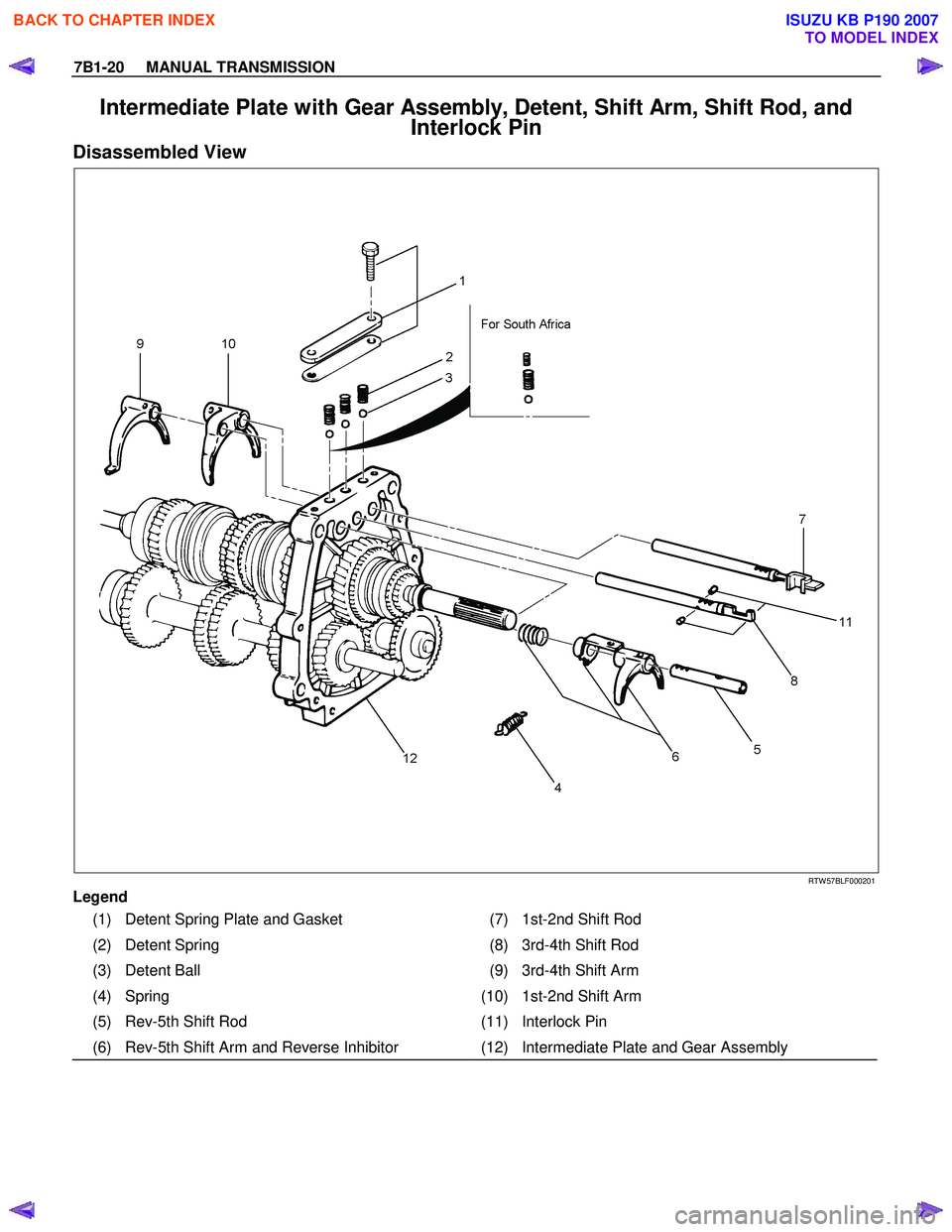
Intermediate Plate with Gear Assembly, Detent, Shift Arm, Shift Rod, and
Interlock Pin
Disassembled View
RTW 57BLF000201
Legend
(1) Detent Spring Plate and Gasket (7) 1st-2nd Shift Rod
(2) Detent Spring (8) 3rd-4th Shift Rod
(3) Detent Ball (9) 3rd-4th Shift Arm
(4) Spring (10) 1st-2nd Shift Arm
(5) Rev-5th Shift Rod (11) Interlock Pin
(6) Rev-5th Shift Arm and Reverse Inhibitor (12) Intermediate Plate and Gear Assembly
BACK TO CHAPTER INDEX
TO MODEL INDEX
ISUZU KB P190 2007
Page 4627 of 6020
MANUAL TRANSMISSION 7B1-21
Disassembly
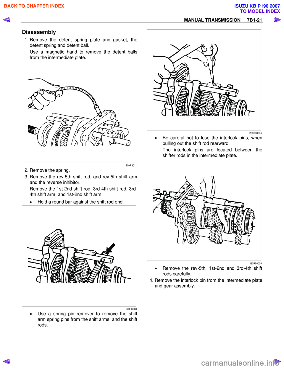
1. Remove the detent spring plate and gasket, the
detent spring and detent ball.
Use a magnetic hand to remove the detent balls
from the intermediate plate.
220RS011
2. Remove the spring.
3. Remove the rev-5th shift rod, and rev-5th shift arm and the reverse inhibitor.
Remove the 1st-2nd shift rod, 3rd-4th shift rod, 3rd-
4th shift arm, and 1st-2nd shift arm.
• Hold a round bar against the shift rod end.
230RS003
• Use a spring pin remover to remove the shift
arm spring pins from the shift arms, and the shift
rods.
230RS0004
•
Be careful not to lose the interlock pins, when
pulling out the shift rod rearward.
The interlock pins are located between the
shifter rods in the intermediate plate.
230RS0005
• Remove the rev-5th, 1st-2nd and 3rd-4th shift
rods carefully.
4. Remove the interlock pin from the intermediate plate and gear assembly.
BACK TO CHAPTER INDEX
TO MODEL INDEX
ISUZU KB P190 2007
Page 4629 of 6020
MANUAL TRANSMISSION 7B1-23
Reassembly
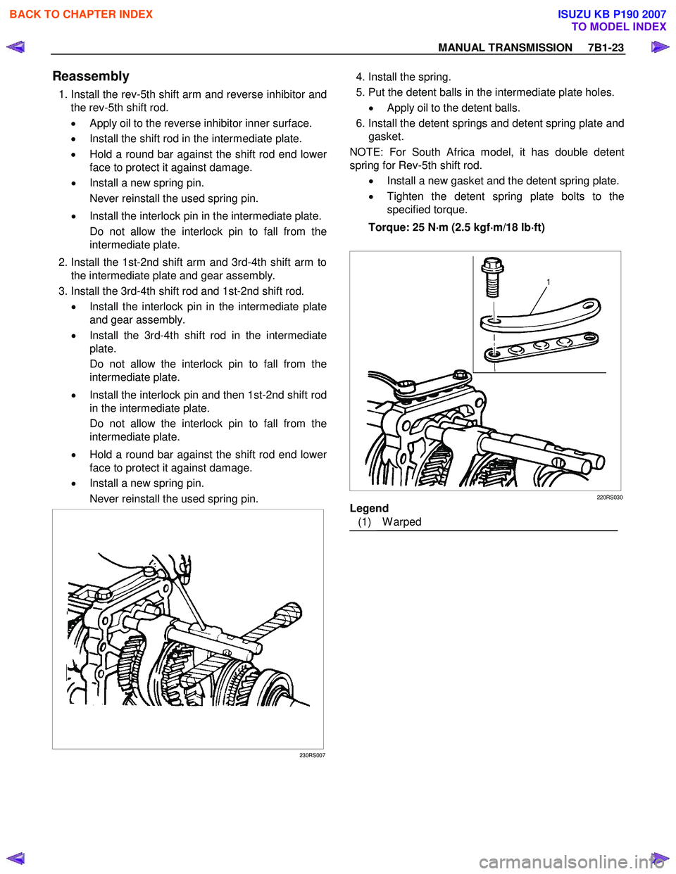
1. Install the rev-5th shift arm and reverse inhibitor and
the rev-5th shift rod.
• Apply oil to the reverse inhibitor inner surface.
• Install the shift rod in the intermediate plate.
• Hold a round bar against the shift rod end lowe
r
face to protect it against damage.
• Install a new spring pin.
Never reinstall the used spring pin.
• Install the interlock pin in the intermediate plate.
Do not allow the interlock pin to fall from the
intermediate plate.
2. Install the 1st-2nd shift arm and 3rd-4th shift arm to the intermediate plate and gear assembly.
3. Install the 3rd-4th shift rod and 1st-2nd shift rod. • Install the interlock pin in the intermediate plate
and gear assembly.
• Install the 3rd-4th shift rod in the intermediate
plate.
Do not allow the interlock pin to fall from the
intermediate plate.
• Install the interlock pin and then 1st-2nd shift rod
in the intermediate plate.
Do not allow the interlock pin to fall from the
intermediate plate.
• Hold a round bar against the shift rod end lowe
r
face to protect it against damage.
• Install a new spring pin.
Never reinstall the used spring pin.
230RS007
4. Install the spring.
5. Put the detent balls in the intermediate plate holes.• Apply oil to the detent balls.
6. Install the detent springs and detent spring plate and gasket.
NOTE: For South Africa model, it has double detent
spring for Rev-5th shift rod.
• Install a new gasket and the detent spring plate.
• Tighten the detent spring plate bolts to the
specified torque.
Torque: 25 N ⋅
⋅⋅
⋅
m (2.5 kgf ⋅
⋅⋅
⋅
m/18 lb ⋅
⋅⋅
⋅
ft)
220RS030
Legend
(1) W arped
BACK TO CHAPTER INDEX
TO MODEL INDEX
ISUZU KB P190 2007
Page 4630 of 6020
7B1-24 MANUAL TRANSMISSION
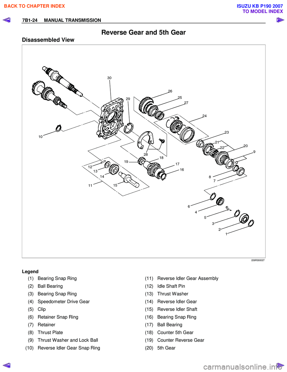
Reverse Gear and 5th Gear
Disassembled View
226R300027
Legend
(1) Bearing Snap Ring (11) Reverse Idler Gear Assembly
(2) Ball Bearing (12) Idle Shaft Pin
(3) Bearing Snap Ring (13) Thrust W asher
(4) Speedometer Drive Gear (14) Reverse Idler Gear
(5) Clip (15) Reverse Idler Shaft
(6) Retainer Snap Ring (16) Bearing Snap Ring
(7) Retainer (17) Ball Bearing
(8) Thrust Plate (18) Counter 5th Gear
(9) Thrust W asher and Lock Ball (19) Counter Reverse Gear
(10) Reverse Idler Gear Snap Ring (20) 5th Gear
BACK TO CHAPTER INDEX
TO MODEL INDEX
ISUZU KB P190 2007
Page 4631 of 6020
MANUAL TRANSMISSION 7B1-25
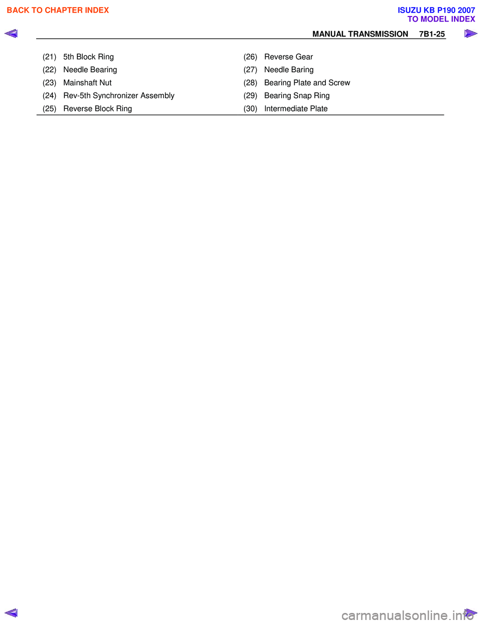
(21) 5th Block Ring (26) Reverse Gear
(22) Needle Bearing (27) Needle Baring
(23) Mainshaft Nut (28) Bearing Plate and Screw
(24) Rev-5th Synchronizer Assembly (29) Bearing Snap Ring
(25) Reverse Block Ring (30) Intermediate Plate
BACK TO CHAPTER INDEX
TO MODEL INDEX
ISUZU KB P190 2007
Page 4632 of 6020
7B1-26 MANUAL TRANSMISSION
Disassembly
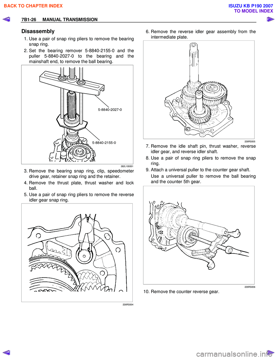
1. Use a pair of snap ring pliers to remove the bearing
snap ring.
2. Set the bearing remover 5-8840-2155-0 and the puller 5-8840-2027-0 to the bearing and the
mainshaft end, to remove the ball bearing.
262L100001
3. Remove the bearing snap ring, clip, speedometer
drive gear, retainer snap ring and the retainer.
4. Remove the thrust plate, thrust washer and lock ball.
5. Use a pair of snap ring pliers to remove the reverse idler gear snap ring.
226RS004
6. Remove the reverse idler gear assembly from the
intermediate plate.
226RS005
7. Remove the idle shaft pin, thrust washer, reverse idler gear, and reverse idler shaft.
8. Use a pair of snap ring pliers to remove the snap ring.
9. Attach a universal puller to the counter gear shaft. Use a universal puller to remove the ball bearing
and the counter 5th gear.
226RS006
10. Remove the counter reverse gear.
BACK TO CHAPTER INDEX
TO MODEL INDEX
ISUZU KB P190 2007
Page 4633 of 6020
MANUAL TRANSMISSION 7B1-27
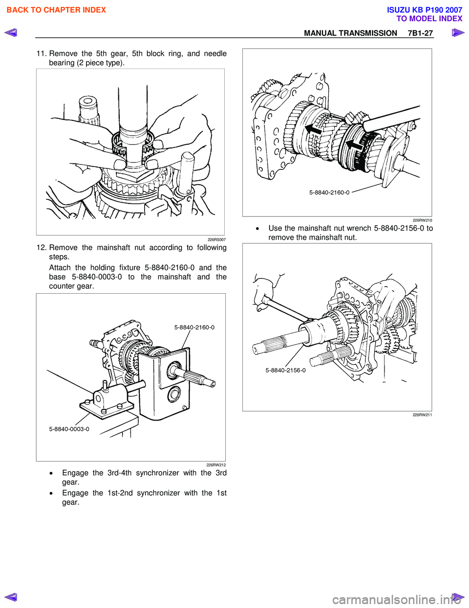
11. Remove the 5th gear, 5th block ring, and needle
bearing (2 piece type).
226RS007
12. Remove the mainshaft nut according to following steps.
Attach the holding fixture 5-8840-2160-0 and the
base 5-8840-0003-0 to the mainshaft and the
counter gear.
226RW 212
• Engage the 3rd-4th synchronizer with the 3rd
gear.
• Engage the 1st-2nd synchronizer with the 1st
gear.
226RW 210
•
Use the mainshaft nut wrench 5-8840-2156-0 to
remove the mainshaft nut.
226RW 211
BACK TO CHAPTER INDEX
TO MODEL INDEX
ISUZU KB P190 2007