CD changer ISUZU KB P190 2007 Workshop Repair Manual
[x] Cancel search | Manufacturer: ISUZU, Model Year: 2007, Model line: KB P190, Model: ISUZU KB P190 2007Pages: 6020, PDF Size: 70.23 MB
Page 1332 of 6020

6E-298 Engine Control System (4JH1)
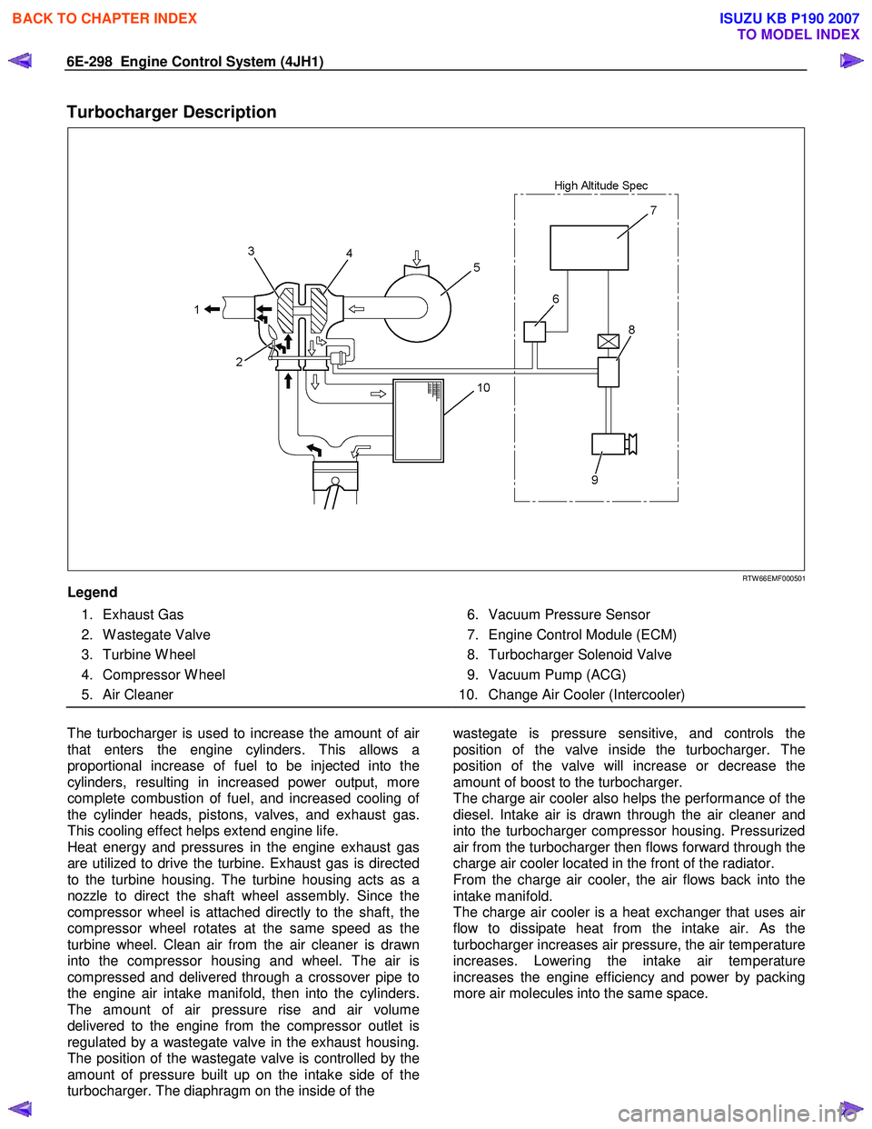
Turbocharger Description
RTW 66EMF000501
Legend
1. Exhaust Gas
2. W astegate Valve
3. Turbine W heel
4. Compressor W heel
5. Air Cleaner
6. Vacuum Pressure Sensor
7. Engine Control Module (ECM)
8. Turbocharger Solenoid Valve
9. Vacuum Pump (ACG)
10. Change Air Cooler (Intercooler)
The turbocharger is used to increase the amount of ai
r
that enters the engine cylinders. This allows a
proportional increase of fuel to be injected into the
cylinders, resulting in increased power output, more
complete combustion of fuel, and increased cooling o
f
the cylinder heads, pistons, valves, and exhaust gas.
This cooling effect helps extend engine life.
Heat energy and pressures in the engine exhaust gas
are utilized to drive the turbine. Exhaust gas is directed
to the turbine housing. The turbine housing acts as a
nozzle to direct the shaft wheel assembly. Since the
compressor wheel is attached directly to the shaft, the
compressor wheel rotates at the same speed as the
turbine wheel. Clean air from the air cleaner is drawn
into the compressor housing and wheel. The air is
compressed and delivered through a crossover pipe to
the engine air intake manifold, then into the cylinders.
The amount of air pressure rise and air volume
delivered to the engine from the compressor outlet is
regulated by a wastegate valve in the exhaust housing.
The position of the wastegate valve is controlled by the
amount of pressure built up on the intake side of the
turbocharger. The diaphragm on the inside of the
wastegate is pressure sensitive, and controls the
position of the valve inside the turbocharger. The
position of the valve will increase or decrease the
amount of boost to the turbocharger.
The charge air cooler also helps the performance of the
diesel. Intake air is drawn through the air cleaner and
into the turbocharger compressor housing. Pressurized
air from the turbocharger then flows forward through the
charge air cooler located in the front of the radiator.
From the charge air cooler, the air flows back into the
intake manifold.
The charge air cooler is a heat exchanger that uses ai
r
flow to dissipate heat from the intake air. As the
turbocharger increases air pressure, the air temperature
increases. Lowering the intake air temperature
increases the engine efficiency and power by packing
more air molecules into the same space.
BACK TO CHAPTER INDEX
TO MODEL INDEX
ISUZU KB P190 2007
Page 1984 of 6020

ENGINE CONTROL SYSTEM (4JK1/4JJ1) 6E-367
The amount of air pressure rise and air volume
delivered to the engine from the compressor outlet is
regulated by a waste gate valve in the exhaust housing.
The position of the waste gate valve is controlled by the
amount of pressure built up on the intake side of the
turbocharger. The diaphragm on the inside of the waste
gate is pressure sensitive, and controls the position of
the valve inside the turbocharger. The position of the
valve will increase or decrease the amount of boost to
the turbocharger. (Standard output engine)
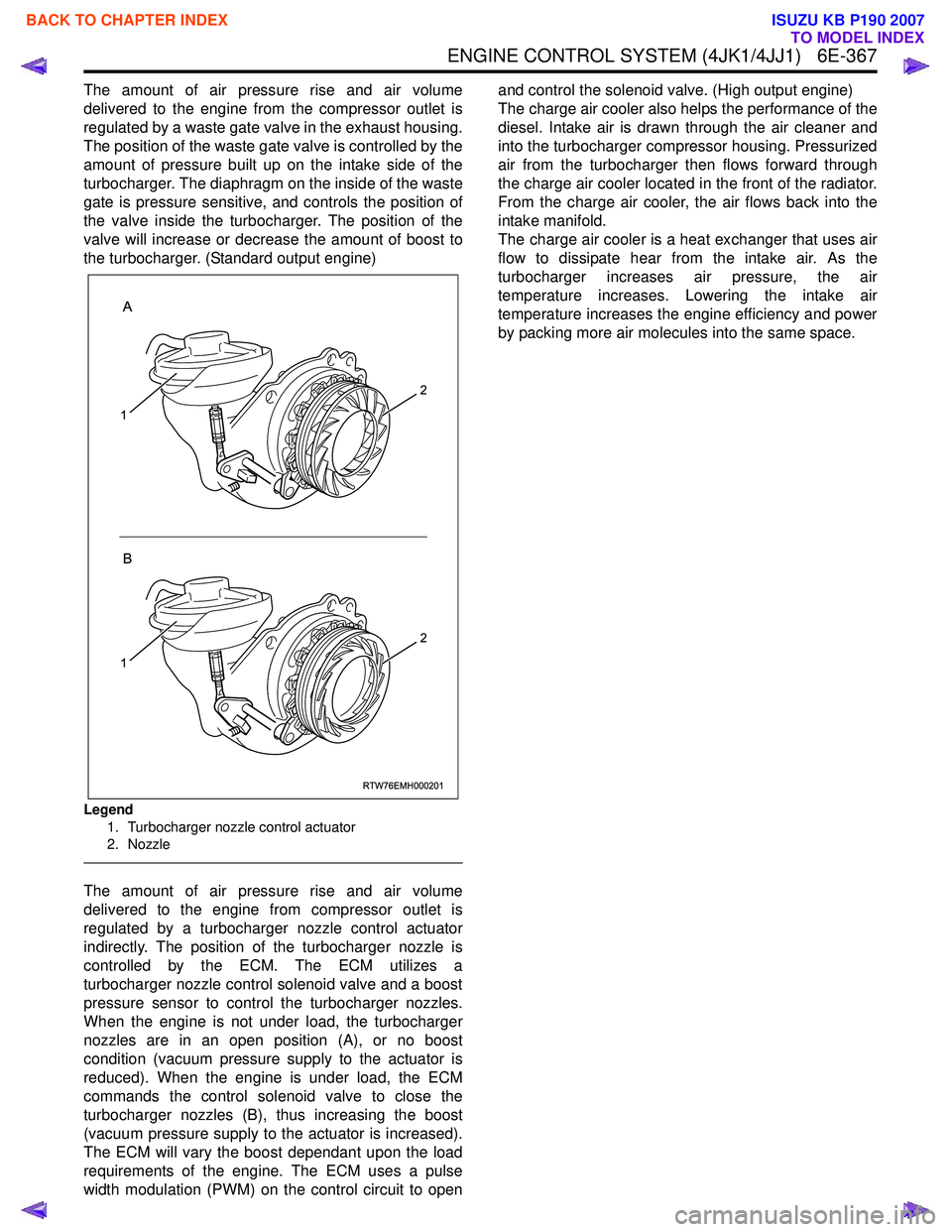
Legend
1. Turbocharger nozzle control actuator
2. Nozzle
The amount of air pressure rise and air volume
delivered to the engine from compressor outlet is
regulated by a turbocharger nozzle control actuator
indirectly. The position of the turbocharger nozzle is
controlled by the ECM. The ECM utilizes a
turbocharger nozzle control solenoid valve and a boost
pressure sensor to control the turbocharger nozzles.
When the engine is not under load, the turbocharger
nozzles are in an open position (A), or no boost
condition (vacuum pressure supply to the actuator is
reduced). When the engine is under load, the ECM
commands the control solenoid valve to close the
turbocharger nozzles (B), thus increasing the boost
(vacuum pressure supply to the actuator is increased).
The ECM will vary the boost dependant upon the load
requirements of the engine. The ECM uses a pulse
width modulation (PWM) on the control circuit to open and control the solenoid valve. (High output engine)
The charge air cooler also helps the performance of the
diesel. Intake air is drawn through the air cleaner and
into the turbocharger compressor housing. Pressurized
air from the turbocharger then flows forward through
the charge air cooler located in the front of the radiator.
From the charge air cooler, the air flows back into the
intake manifold.
The charge air cooler is a heat exchanger that uses air
flow to dissipate hear from the intake air. As the
turbocharger increases air pressure, the air
temperature increases. Lowering the intake air
temperature increases the engine efficiency and power
by packing more air molecules into the same space.
RTW76EMH000201
A
B
1
2
1
2
BACK TO CHAPTER INDEX
TO MODEL INDEX
ISUZU KB P190 2007
Page 5887 of 6020

11A-36 IMMOBILIZER CONTROL SYSTEM (4JK1/4JJ1/HFV6)
Resetting and Programming
Resetting and Programming Guidelines
Notice:The security information must be programmed
when the ICU, ECM, PIM or transponder key(s) is
replaced, or transponder key(s) is added.
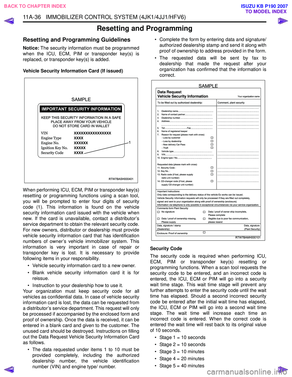
Vehicle Security Information Card (If issued)
When performing ICU, ECM, PIM or transponder key(s)
resetting or programming functions using a scan tool,
you will be prompted to enter four digits of security
code (1). This information is found on the vehicle
security information card issued with the vehicle when
new. If the card is unavailable, contact a distributor’s
service department to obtain the relevant security code.
For new owners, distributor or dealership must provide
vehicle security information card that has identification
numbers of owner’s vehicle immobilizer system. This
information is very important in case of repair or
transponder key is lost. It is necessary to provide
following items in your responsibility.
• Vehicle security information card to a new owner.
• Blank vehicle security information card it is for reissue.
• Instruction to your dealership how to use it.
Your organization must keep security code for all
vehicles as confidential data. In case of vehicle security
information card is lost, the data can be requested from
a distributor’s service department. This request will only
be processed if accompanied by the enclosed form and
proof of ownership. Once the data is received, it can be
entered in a blank card and given to the customer. The
unused card should be destroyed. Instructions on filling
out the Data Request Vehicle Security Information Card
as follows.
• The data requested under items 1 to 10 must be provided completely, including the authorized
dealership number, the vehicle identification
number (VIN) and engine type/ number. • Complete the form by entering data and signature/
authorized dealership stamp and send it along with
proof of ownership to address provided in the form.
• The requested data will be sent by fax to dealership that made the request after your
organization has confirmed that the information is
correct.
Security Code
The security code is required when performing ICU,
ECM, PIM or transponder key(s) resetting or
programming functions. When a scan tool requests the
security code to be entered, and an incorrect code is
entered, the ICU, ECM or PIM will go into a security
wait time stage. This wait time stage will prevent any
further attempts to enter the security code until the wait
time has elapsed. Should a second incorrect security
code be entered after the initial wait time has elapsed,
the ICU, ECM or PIM will go into a second wait time
stage. The wait time will increase each time an
incorrect code is entered. When the correct code is
entered the wait time will rest back to its original value
of 10 seconds.
• Stage 1 = 10 seconds
• Stage 2 = 10 seconds
• Stage 3 = 10 minutes
• Stage 4 = 20 minutes
• Stage 5 = 40 minutes
RTW7BASH000401
KEEP THIS SECURITY INFORMATION IN A SAFE PLACE AWAY FROM YOUR VEHICLEDO NOT STORE CARD IN WALLET
1
SAMPLE
RTW7BAMH000101
Your organization name
To be filled out by authorized dealership: Comment, plant security
1. Dealership name.......................................................... ....................................................................
....................................................................
....................................................................
....................................................................
....................................................................
....................................................................
....................................................................
....................................................................
.................................................................... ....................................................................
....................................................................
....................................................................
....................................................................
....................................................................
2. Name of contact partner.............................................
6. Name of registered keeper
7. Reason for request (please mark with cross)
3. Dealership number......................................................
4. Address.......................................................................
8. Vehicle type................................................................
9. VIN................................................................................
10. Engine type / No.........................................................
11. Security Code :
12. Key No. :
13. Radio code (if lost, please supply radio unit number)
14. CD-changer code (if lost, please
supply CD-changer unit number)
Requested data (please mark with cross)
5. Tel:....................................Fax....................................
.....................................................................................
- Loss by customer
- Loss by dealership
- New delivery Car Pass
- Theft
Important Instructions:
Comments form Plant Security
Data, signature / stamp Data, signature
(Dealership) (Plant Security)
Enclosure: Proof of ownership Only data corresponding to the delivery status of the vehicle Ex works can be Issued.
Vehicle Security Information requests will only be processed if they are filled out completely,
signed and sent to your organization along with proof of ownership (enclosure).
Information via telephone is only possible in exceptional circumstances via your service organization.
No signature Data / proof of owner ship incomplete,
Please complete
Data / proof of ownership missing,
Please supply Illegible due to poor fax communication,
please resend
SAMPLE
BACK TO CHAPTER INDEX TO MODEL INDEX
ISUZU KB P190 2007