DTC ISUZU KB P190 2007 Workshop Repair Manual
[x] Cancel search | Manufacturer: ISUZU, Model Year: 2007, Model line: KB P190, Model: ISUZU KB P190 2007Pages: 6020, PDF Size: 70.23 MB
Page 594 of 6020

5A -1 BR AKE CON TROL SY STE M
Brake (E BD) Warning Lamp ......................................................................................... 5 A -25
Tech 2 Scan Tool .......................................................................................................... 5 A -2 6
Da ta List ( T ech 2 ).......................................................................................................... 5 A -32
Diagnostic Trouble Codes ................................................................................................ 5 A -33
Diagnosis By " A BS" Warning Lamp Illumination Patter n.............................................. 5 A -35
Basic Diagnostic Flow Chart ............................................................................................ 5 A -38
Basic Inspec tion Procedure ............................................................................................. 5 A -40
1. Basic Inspec tion of Ser vice Brake .......................................................................... 5 A -40
2. Ground Inspection .................................................................................................... 5 A -40
W heel Speed Sensor Inspec tion Procedure.................................................................... 5 A -41
Symptom Diagnosis .......................................................................................................... 5A- 42
ABS Works Frequently But Vehicle Does Not Decelerate ......................................... 5A-42
Uneven Braking Occurs While ABS Works ................................................................ 5A-43
The Wheels Are Locked................................................................................................ 5A-43
Brake Pedal Feed Is Abnormal .................................................................................... 5A-44
Braking Sound (From EHCU) Is Heard While Not Braking ........................................ 5A-45
No ABS Warning Lamp ................................................................................................. 5A-46
ABS Warning Lamp ON Steady.................................................................................... 5A-47
DTC C0221 (Flash Code 21) Front Right Wheel Speed Sensor
Short Circuit or Circuit Open ......................................................................................... 5A-48
DTC C0222 (Flash Code 22) Front Right Wheel Speed Sensor Signal Malfunction..... 5A-50
DTC C0225 (Flash Code 25) Front Left Wheel Speed Sensor Short Circuit or
Circuit Open ................................................................................................................ .... 5A-52
DTC C0226 (Flash Code 26) Front Left Wheel Speed Sensor Signal Malfunction ....... 5A-54
DTC C0231 (Flash Code 31) Rear Right Wheel Speed Sensor Short Circuit or
Circuit Open ................................................................................................................ .... 5A-56
DTC C0232 (Flash Code 32) Rear Right Wheel Speed Sensor Signal Malfunction ...... 5A-58
DTC C0235 (Flash Code 35) Rear Left Wheel Speed Sensor Short Circuit or
Circuit Open ................................................................................................................ .... 5A-60
DTC C0236 (Flash Code 36) Rear Left Wheel Speed Sensor Signal Malfunction ........ 5A-62
DTC C0238 (Flash Code 38) Front Speed Sensor Correlation ....................................... 5A-64
DTC C0241 (Flash Code 41) Front Right Hold Solenoid Valve Circuit .......................... 5A-66
DTC C0242 (Flash Code 42) Front Right Release Solenoid Valve Circuit..................... 5A-66
DTC C0245 (Flash Code 45) Front Left Hold Solenoid Valve Circuit ............................. 5A-68
DTC C0246 (Flash Code 46) Front Left Release Solenoid Valve Circuit ....................... 5A-68
BACK TO CHAPTER INDEX
TO MODEL INDEX
ISUZU KB P190 2007
Page 595 of 6020
BRAKE CON TROL SY STE M 5 A-2
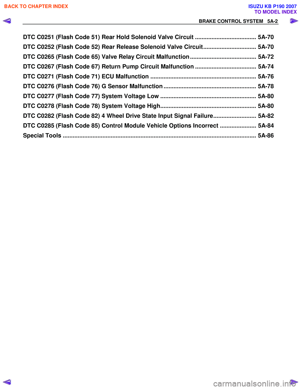
DTC C0251 (Flash Code 51) Rear Hold Solenoid Valve Circuit ..................................... 5A-70
DTC C0252 (Flash Code 52) Rear Release Solenoid Valve Circuit ................................ 5A-70
DTC C0265 (Flash Code 65) Valve Relay Circuit Malfunction ........................................ 5A-72
DTC C0267 (Flash Code 67) Return Pump Circuit Malfunction ..................................... 5A-74
DTC C0271 (Flash Code 71) ECU Malfunction ................................................................ 5A-76
DTC C0276 (Flash Code 76) G Sensor Malfunction ........................................................ 5A-78
DTC C0277 (Flash Code 77) System Voltage Low .......................................................... 5A-80
DTC C0278 (Flash Code 78) System Voltage High.......................................................... 5A-80
DTC C0282 (Flash Code 82) 4 Wheel Drive State Input Signal Failure.......................... 5A-82
DTC C0285 (Flash Code 85) Control Module Vehicle Options Incorrect ...................... 5A-84
Special Tools .................................................................................................................. ... 5A-86
BACK TO CHAPTER INDEX
TO MODEL INDEX
ISUZU KB P190 2007
Page 613 of 6020
5A-20 BRAKE CONTROL SYSTEM
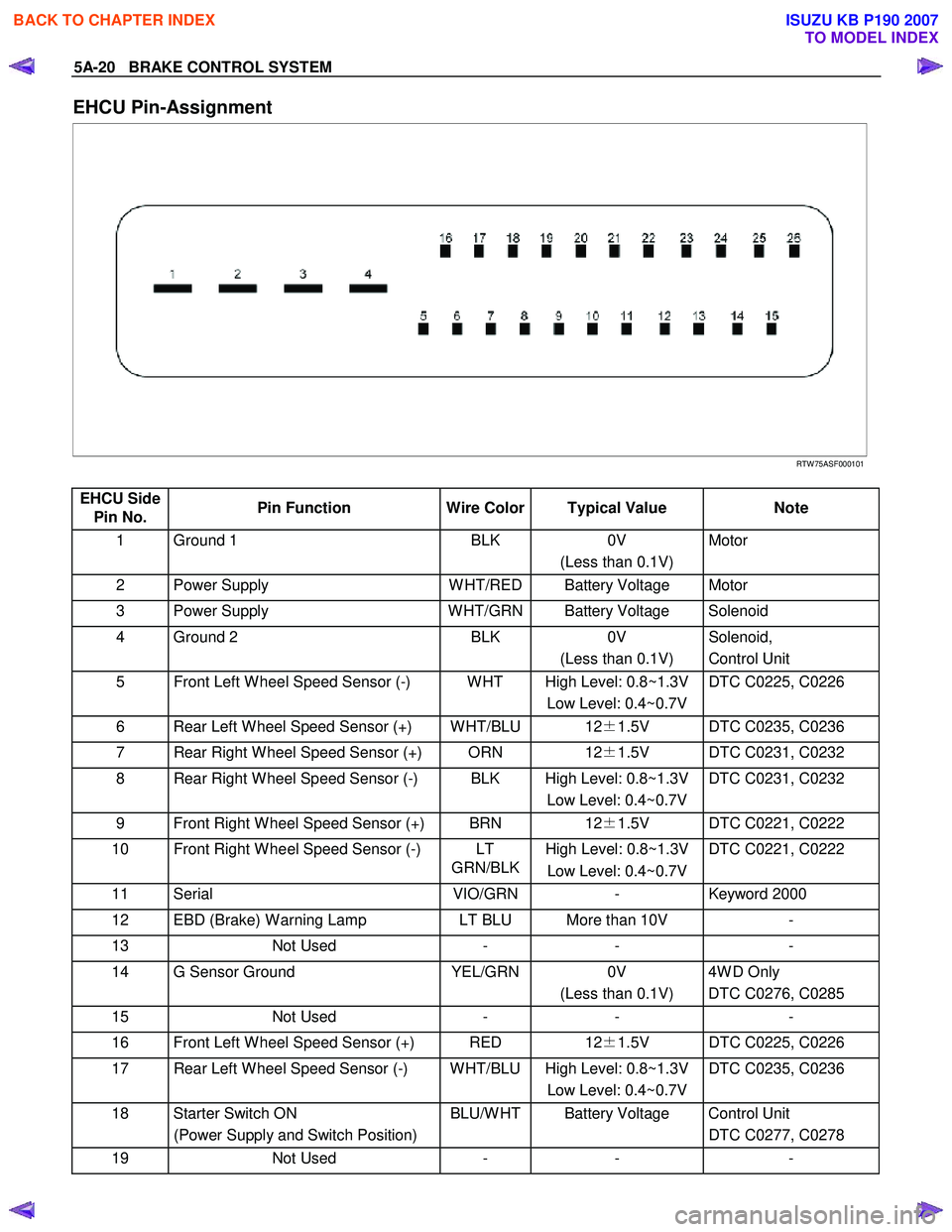
EHCU Pin-Assignment
RTW 75ASF000101
EHCU Side Pin No. Pin Function
Wire Color Typical Value Note
1 Ground 1 BLK 0V
(Less than 0.1V) Motor
2 Power Supply
W HT/RED Battery Voltage Motor
3 Power Supply W HT/GRN Battery Voltage Solenoid
4 Ground 2 BLK 0V
(Less than 0.1V) Solenoid,
Control Unit
5 Front Left W heel Speed Sensor (-) W HT High Level: 0.8~1.3V Low Level: 0.4~0.7V DTC C0225, C0226
6 Rear Left W heel Speed Sensor (+) W HT/BLU 12
±1.5V DTC C0235, C0236
7 Rear Right W heel Speed Sensor (+) ORN 12±1.5V DTC C0231, C0232
8 Rear Right W heel Speed Sensor (-) BLK High Level: 0.8~1.3V
Low Level: 0.4~0.7V DTC C0231, C0232
9 Front Right W heel Speed Sensor (+) BRN
12±1.5V DTC C0221, C0222
10 Front Right W heel Speed Sensor (-) LT
GRN/BLKHigh Level: 0.8~1.3V
Low Level: 0.4~0.7V DTC C0221, C0222
11 Serial
VIO/GRN- Keyword 2000
12 EBD (Brake) W arning Lamp LT BLU More than 10V -
13 Not Used - - -
14 G Sensor Ground YEL/GRN0V
(Less than 0.1V) 4W D Only
DTC C0276, C0285
15 Not Used - - -
16 Front Left W heel Speed Sensor (+) RED 12±1.5V DTC C0225, C0226
17 Rear Left W heel Speed Sensor (-) W HT/BLU High Level: 0.8~1.3V
Low Level: 0.4~0.7V DTC C0235, C0236
18 Starter Switch ON
(Power Supply and Switch Position) BLU/W HT Battery Voltage Control Unit
DTC C0277, C0278
19 Not Used - - -
BACK TO CHAPTER INDEX
TO MODEL INDEX
ISUZU KB P190 2007
Page 614 of 6020
BRAKE CONTROL SYSTEM 5A-21
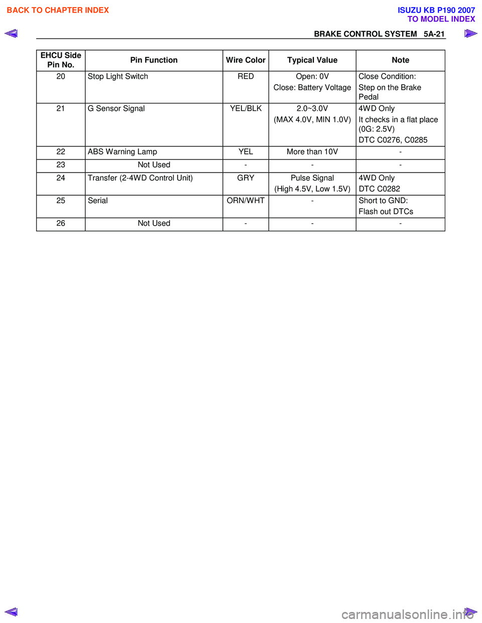
EHCU Side
Pin No. Pin Function
Wire Color Typical Value Note
20 Stop Light Switch RED Open: 0V
Close: Battery Voltage Close Condition:
Step on the Brake
Pedal
21 G Sensor Signal YEL/BLK 2.0~3.0V
(MAX 4.0V, MIN 1.0V) 4W D Only
It checks in a flat place
(0G: 2.5V)
DTC C0276, C0285
22 ABS W arning Lamp YEL More than 10V -
23 Not Used - - -
24 Transfer (2-4W D Control Unit) GRY Pulse Signal
(High 4.5V, Low 1.5V) 4W D Only
DTC C0282
25 Serial ORN/W HT- Short to GND:
Flash out DTCs
26 Not Used - - -
BACK TO CHAPTER INDEX
TO MODEL INDEX
ISUZU KB P190 2007
Page 617 of 6020
5A-24 BRAKE CONTROL SYSTEM
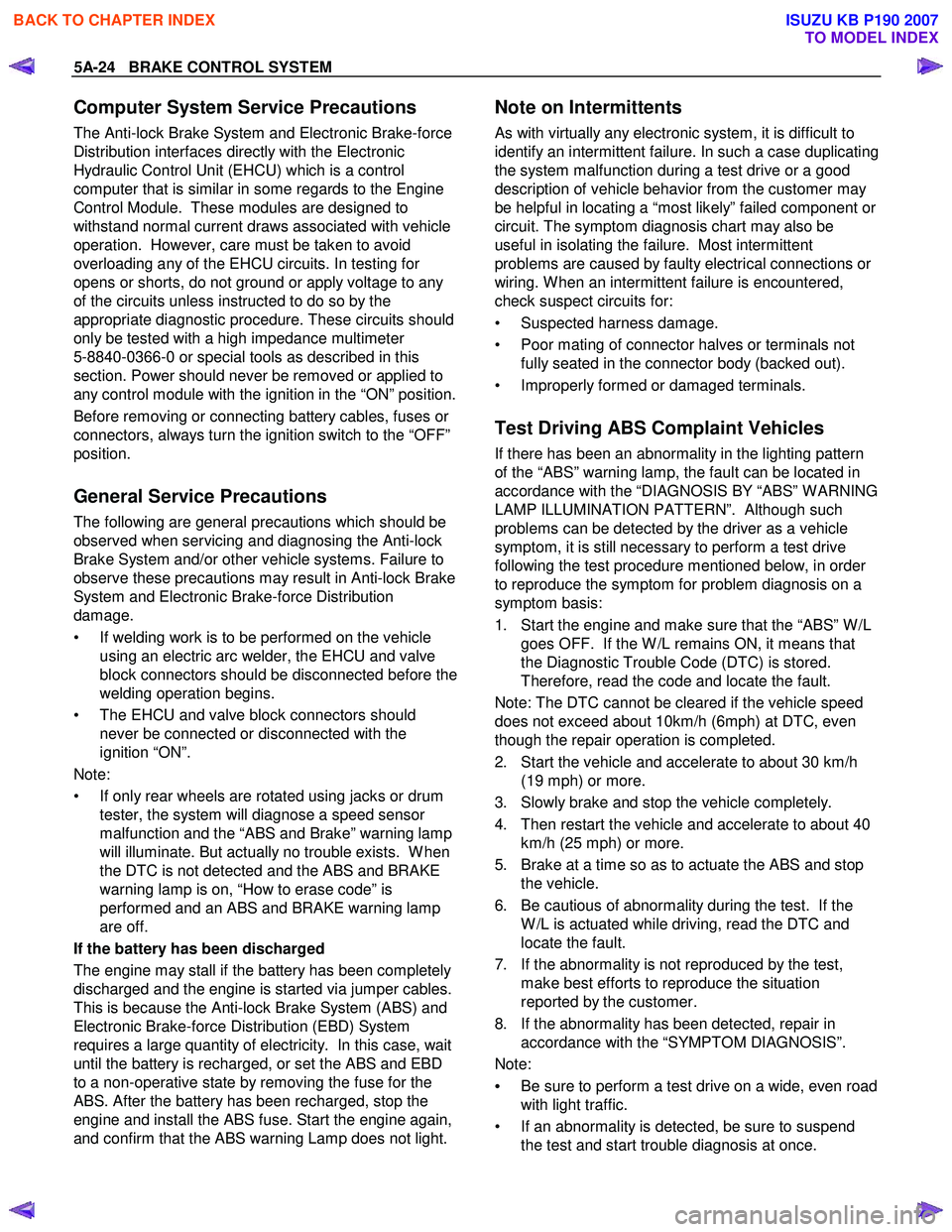
Computer System Service Precautions
The Anti-lock Brake System and Electronic Brake-force
Distribution interfaces directly with the Electronic
Hydraulic Control Unit (EHCU) which is a control
computer that is similar in some regards to the Engine
Control Module. These modules are designed to
withstand normal current draws associated with vehicle
operation. However, care must be taken to avoid
overloading any of the EHCU circuits. In testing for
opens or shorts, do not ground or apply voltage to any
of the circuits unless instructed to do so by the
appropriate diagnostic procedure. These circuits should
only be tested with a high impedance multimeter
5-8840-0366-0 or special tools as described in this
section. Power should never be removed or applied to
any control module with the ignition in the “ON” position.
Before removing or connecting battery cables, fuses or
connectors, always turn the ignition switch to the “OFF”
position.
General Service Precautions
The following are general precautions which should be
observed when servicing and diagnosing the Anti-lock
Brake System and/or other vehicle systems. Failure to
observe these precautions may result in Anti-lock Brake
System and Electronic Brake-force Distribution
damage.
• If welding work is to be performed on the vehicle using an electric arc welder, the EHCU and valve
block connectors should be disconnected before the
welding operation begins.
• The EHCU and valve block connectors should never be connected or disconnected with the
ignition “ON”.
Note:
• If only rear wheels are rotated using jacks or drum tester, the system will diagnose a speed sensor
malfunction and the “ABS and Brake” warning lamp
will illuminate. But actually no trouble exists. W hen
the DTC is not detected and the ABS and BRAKE
warning lamp is on, “How to erase code” is
performed and an ABS and BRAKE warning lamp
are off.
If the battery has been discharged
The engine may stall if the battery has been completely
discharged and the engine is started via jumper cables.
This is because the Anti-lock Brake System (ABS) and
Electronic Brake-force Distribution (EBD) System
requires a large quantity of electricity. In this case, wait
until the battery is recharged, or set the ABS and EBD
to a non-operative state by removing the fuse for the
ABS. After the battery has been recharged, stop the
engine and install the ABS fuse. Start the engine again,
and confirm that the ABS warning Lamp does not light.
Note on Intermittents
As with virtually any electronic system, it is difficult to
identify an intermittent failure. In such a case duplicating
the system malfunction during a test drive or a good
description of vehicle behavior from the customer may
be helpful in locating a “most likely” failed component or
circuit. The symptom diagnosis chart may also be
useful in isolating the failure. Most intermittent
problems are caused by faulty electrical connections or
wiring. W hen an intermittent failure is encountered,
check suspect circuits for:
• Suspected harness damage.
• Poor mating of connector halves or terminals not fully seated in the connector body (backed out).
• Improperly formed or damaged terminals.
Test Driving ABS Complaint Vehicles
If there has been an abnormality in the lighting pattern
of the “ABS” warning lamp, the fault can be located in
accordance with the “DIAGNOSIS BY “ABS” W ARNING
LAMP ILLUMINATION PATTERN”. Although such
problems can be detected by the driver as a vehicle
symptom, it is still necessary to perform a test drive
following the test procedure mentioned below, in order
to reproduce the symptom for problem diagnosis on a
symptom basis:
1. Start the engine and make sure that the “ABS” W /L
goes OFF. If the W /L remains ON, it means that
the Diagnostic Trouble Code (DTC) is stored.
Therefore, read the code and locate the fault.
Note: The DTC cannot be cleared if the vehicle speed
does not exceed about 10km/h (6mph) at DTC, even
though the repair operation is completed.
2. Start the vehicle and accelerate to about 30 km/h (19 mph) or more.
3. Slowly brake and stop the vehicle completely.
4. Then restart the vehicle and accelerate to about 40 km/h (25 mph) or more.
5. Brake at a time so as to actuate the ABS and stop the vehicle.
6. Be cautious of abnormality during the test. If the W /L is actuated while driving, read the DTC and
locate the fault.
7. If the abnormality is not reproduced by the test, make best efforts to reproduce the situation
reported by the customer.
8. If the abnormality has been detected, repair in accordance with the “SYMPTOM DIAGNOSIS”.
Note:
• Be sure to perform a test drive on a wide, even road
with light traffic.
• If an abnormality is detected, be sure to suspend the test and start trouble diagnosis at once.
BACK TO CHAPTER INDEX
TO MODEL INDEX
ISUZU KB P190 2007
Page 620 of 6020
BRAKE CONTROL SYSTEM 5A-27
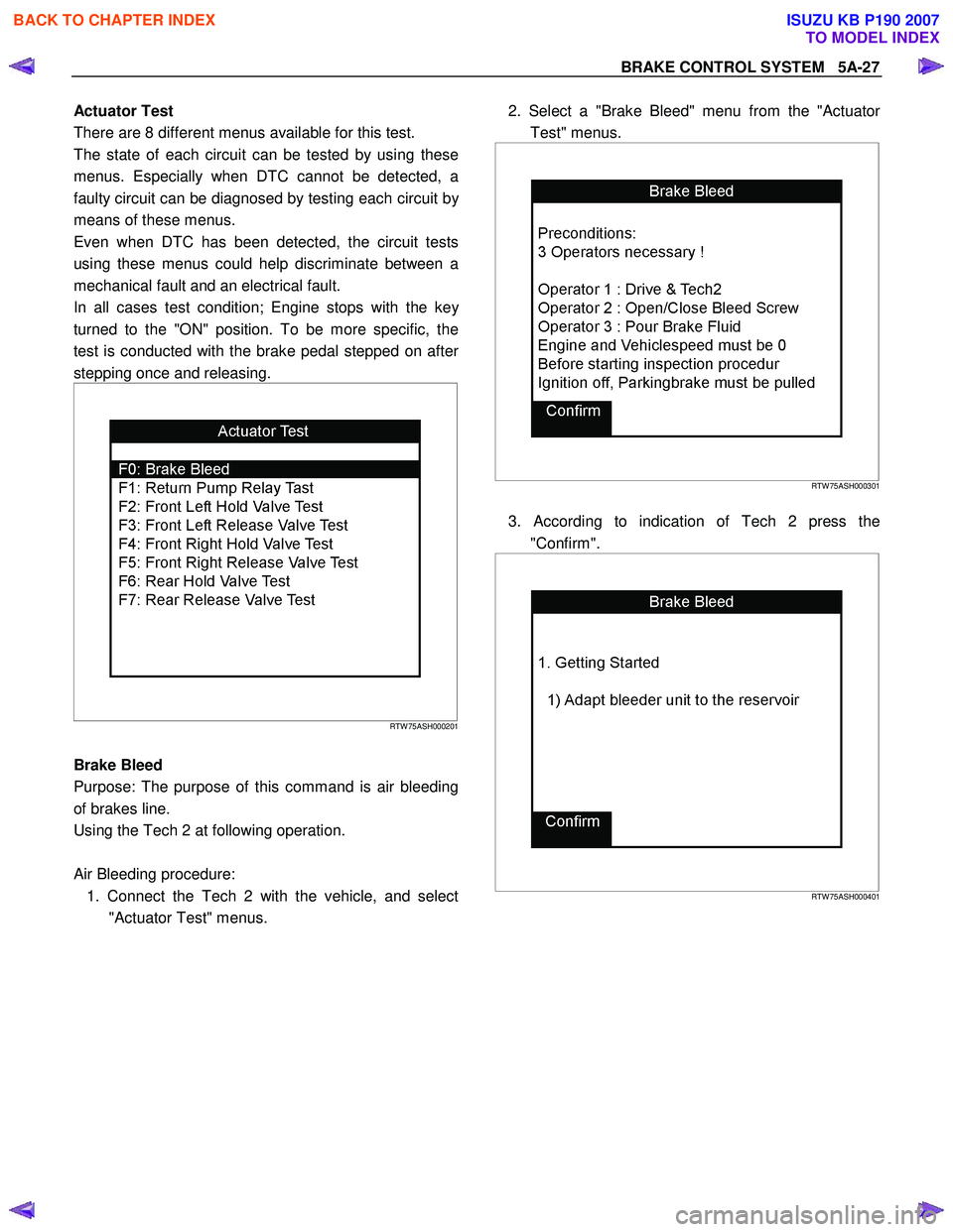
Actuator Test
There are 8 different menus available for this test.
The state of each circuit can be tested by using these
menus. Especially when DTC cannot be detected, a
faulty circuit can be diagnosed by testing each circuit b
y
means of these menus.
Even when DTC has been detected, the circuit tests
using these menus could help discriminate between a
mechanical fault and an electrical fault.
In all cases test condition; Engine stops with the ke
y
turned to the "ON" position. To be more specific, the
test is conducted with the brake pedal stepped on afte
r
stepping once and releasing.
RTW 75ASH000201
Brake Bleed
Purpose: The purpose of this command is air bleeding
of brakes line.
Using the Tech 2 at following operation.
Air Bleeding procedure: 1. Connect the Tech 2 with the vehicle, and select "Actuator Test" menus.
2. Select a "Brake Bleed" menu from the "Actuato
r
Test" menus.
RTW 75ASH000301
3. According to indication of Tech 2 press the
"Confirm".
RTW 75ASH000401
BACK TO CHAPTER INDEX
TO MODEL INDEX
ISUZU KB P190 2007
Page 621 of 6020
5A-28 BRAKE CONTROL SYSTEM
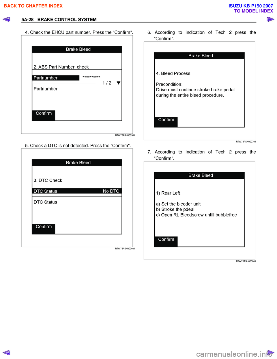
4. Check the EHCU part number. Press the "Confirm".
RTW 75ASH000501
5. Check a DTC is not detected. Press the "Confirm".
RTW 75ASH000601
6. According to indication of Tech 2 press the
"Confirm".
RTW 75ASH000701
7. According to indication of Tech 2 press the
"Confirm".
RTW 75ASH000801
BACK TO CHAPTER INDEX
TO MODEL INDEX
ISUZU KB P190 2007
Page 625 of 6020
5A-32 BRAKE CONTROL SYSTEM
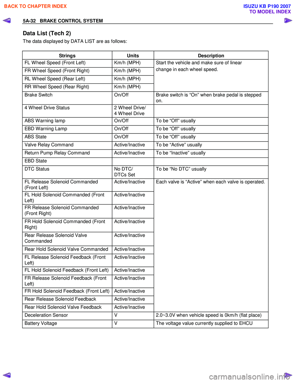
Data List (Tech 2)
The data displayed by DATA LIST are as follows:
Strings Units Description
FL W heel Speed (Front Left) Km/h (MPH)
FR W heel Speed (Front Right) Km/h (MPH)
RL W heel Speed (Rear Left) Km/h (MPH)
RR W heel Speed (Rear Right) Km/h (MPH) Start the vehicle and make sure of linear
change in each wheel speed.
Brake Switch On/Off Brake switch is “On” when brake pedal is stepped
on.
4 W heel Drive Status 2 W heel Drive/
4 W heel Drive
ABS W arning lamp
On/Off To be “Off” usually
EBD W arning Lamp On/Off To be “Off” usually
ABS State On/Off To be “Off” usually
Valve Relay Command Active/Inactive To be “Active” usually
Return Pump Relay Command Active/Inactive To be “Inactive” usually
EBD State
DTC Status No DTC/
DTCs Set To be “No DTC” usually
FL Release Solenoid Commanded
(Front Left) Active/Inactive
FL Hold Solenoid Commanded (Front
Left) Active/Inactive
FR Release Solenoid Commanded
(Front Right) Active/Inactive
FR Hold Solenoid Commanded (Front
Right) Active/Inactive
Rear Release Solenoid Valve
Commanded Active/Inactive
Rear Hold Solenoid Valve Commanded Active/Inactive
FL Release Solenoid Feedback (Front
Left) Active/Inactive
FL Hold Solenoid Feedback (Front Left) Active/Inactive
FR Release Solenoid Feedback (Front
Left) Active/Inactive
FR Hold Solenoid Feedback (Front Left) Active/Inactive
Rear Release Solenoid Feedback Active/Inactive
Rear Hold Solenoid Valve Feedback Active/Inactive Each valve is “Active” when each valve is operated.
Deceleration Sensor
V 2.0~3.0V when vehicle speed is 0km/h (flat place)
Battery Voltage V The voltage value currently supplied to EHCU
BACK TO CHAPTER INDEX
TO MODEL INDEX
ISUZU KB P190 2007
Page 626 of 6020
BRAKE CONTROL SYSTEM 5A-33
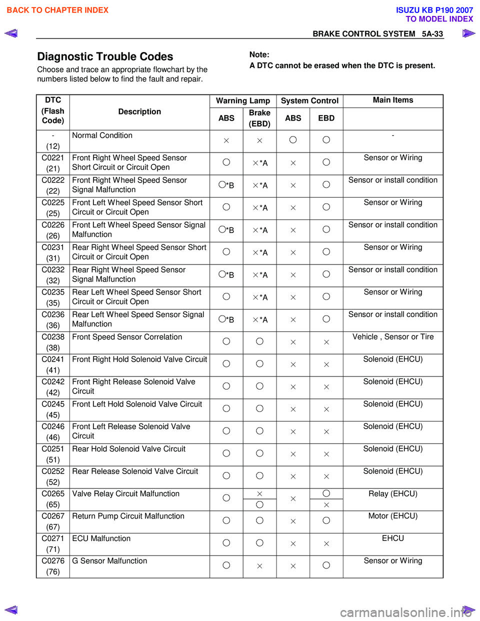
Diagnostic Trouble Codes
Choose and trace an appropriate flowchart by the
numbers listed below to find the fault and repair.
Note:
A DTC cannot be erased when the DTC is present.
Warning Lamp System Control Main Items
DTC
(Flash Code) Description
ABS Brake
(EBD) ABS EBD
-
(12) Normal Condition
× × -
C0221
(21) Front Right W heel Speed Sensor
Short Circuit or Circuit Open ×*A × Sensor or W iring
C0222
(22) Front Right W heel Speed Sensor
Signal Malfunction *B ×*A × Sensor or install condition
C0225
(25) Front Left W heel Speed Sensor Short
Circuit or Circuit Open ×*A × Sensor or W iring
C0226
(26) Front Left W heel Speed Sensor Signal
Malfunction *B ×*A × Sensor or install condition
C0231
(31) Rear Right W heel Speed Sensor Short
Circuit or Circuit Open ×*A × Sensor or W iring
C0232
(32) Rear Right W heel Speed Sensor
Signal Malfunction *B ×*A × Sensor or install condition
C0235
(35) Rear Left W heel Speed Sensor Short
Circuit or Circuit Open ×*A × Sensor or W iring
C0236
(36) Rear Left W heel Speed Sensor Signal
Malfunction *B ×*A × Sensor or install condition
C0238
(38) Front Speed Sensor Correlation
× × Vehicle , Sensor or Tire
C0241
(41) Front Right Hold Solenoid Valve Circuit
× × Solenoid (EHCU)
C0242
(42) Front Right Release Solenoid Valve
Circuit × × Solenoid (EHCU)
C0245
(45) Front Left Hold Solenoid Valve Circuit
× × Solenoid (EHCU)
C0246
(46) Front Left Release Solenoid Valve
Circuit × × Solenoid (EHCU)
C0251
(51) Rear Hold Solenoid Valve Circuit
× × Solenoid (EHCU)
C0252
(52) Rear Release Solenoid Valve Circuit
× × Solenoid (EHCU)
×
C0265
(65) Valve Relay Circuit Malfunction
×
× Relay (EHCU)
C0267
(67) Return Pump Circuit Malfunction
× Motor (EHCU)
C0271
(71) ECU Malfunction
× × EHCU
C0276
(76) G Sensor Malfunction
× × Sensor or W iring
BACK TO CHAPTER INDEX
TO MODEL INDEX
ISUZU KB P190 2007
Page 627 of 6020

5A-34 BRAKE CONTROL SYSTEM
Warning Lamp System Control Main Items DTC
(Flash Code) Description
ABS Brake
(EBD) ABS EBD
× × Battery, W iring or EHCU
(less than 8V) C0277 (77) System Voltage Low
× × Battery or W iring
(less than 10V)
C0278 (78) System Voltage High
× × Battery or W iring EHCU
C0282
(82) 4 W heel Drive State Input Signal
Failure × × W iring
C0285
(85) Control Module Vehicle Options
Incorrect × × Vehicle (Sensor or EHCU)
*A : W hen three or more failures are detected, the EBD warning lamp is "ON" and control is canceled.
*B : The ABS lamp is “OFF” when the ABS lamp is “ON” after a repair, until the vehicle’s speed becomes
more than 10km/h (6mph) in the following ignition
cycle and failure is not detected.
BACK TO CHAPTER INDEX
TO MODEL INDEX
ISUZU KB P190 2007