Distribution ISUZU KB P190 2007 Workshop Repair Manual
[x] Cancel search | Manufacturer: ISUZU, Model Year: 2007, Model line: KB P190, Model: ISUZU KB P190 2007Pages: 6020, PDF Size: 70.23 MB
Page 593 of 6020
BRAKE CON TROL SY STE M 5 A
EHCU, Brake Pipe Diagram .......................................................................................... 5A-5
Hydraulic Unit (H/U) ...................................................................................................... 5A-6
Normal Braking ............................................................................................................. 5A- 7
Pressure Isolation (Pressure Maintain)....................................................................... 5A-8
Pressure Reduction ...................................................................................................... 5A-9
Brake Release ............................................................................................................... 5A -10
Circuit Diagram ............................................................................................................. 5A -11
Connector List ............................................................................................................... 5 A-14
Parts Location ............................................................................................................... 5 A-16
EHCU Pin-Assignment .................................................................................................. 5A-20
System Components .................................................................................................... 5A-22
Electronic Hydraulic Control Unit (EHCU).............................................................. 5A-22
ABS Warning Lamp .................................................................................................. 5A-22
Wheel Speed Sensor (WSS) .................................................................................... 5A-22
G Sensor ................................................................................................................... 5A- 22
Normal and Anti-lock Braking ................................................................................. 5A-22
Electronic Brake-force Distribution (EBD) System................................................ 5A-23
Brake Pedal Travel ................................................................................................... 5A-23
Acronyms and Abbreviations....................................................................................... 5A-23
General Diagnosis ............................................................................................................. 5A-23
General Information ...................................................................................................... 5A-23
ABS Service Precautions ............................................................................................. 5A-23
Computer System Service Precautions ...................................................................... 5A-24
General Service Precautions ....................................................................................... 5A-24
Note on Intermittents .................................................................................................... 5A-24
Test Driving ABS Complaint Vehicles ......................................................................... 5A-24
"ABS" Warning Lamp ................................................................................................... 5A-25
Normal Operation .......................................................................................................... 5A-2 5
SECTION 5A
BRAKE CONTROL SYSTEM
TABLE OF CONTENTS
Ser vice Precau tion ............................................................................................................ 5A -3
General Descrip tio n........................................................................................................... 5A -4
BACK TO CHAPTER INDEX
TO MODEL INDEX
ISUZU KB P190 2007
Page 597 of 6020

5A-4 BRAKE CONTROL SYSTEM
General Description
EHCU has controlled ABS (Anti-lock Brake System) and
EBD (Electronic Brake-force Distribution System). ABS
works on all four wheels. EBD system works on rear 2
wheels. A combination of wheel speed sensor and
Electronic Hydraulic Control Unit (EHCU) can determine
when a wheel is about to stop turning and adjust brake
pressure to maintain best braking. This system helps the driver maintain greater control of
the vehicle under heavy braking conditions.
Note: The Electronic Hydraulic Control Unit (EHCU)
comprises the Hydraulic Unit (H/U) and Control Unit.
This illustration is based on RHD model
RTW 75AMF001101
Legend
(1) Electronic (6) Front Left W heel Speed Sensor
(2) Hydraulic (7) Rear Right W heel Speed Sensor
(3) Hydraulic Unit (H/U) (8) Rear Left W heel Speed Sensor
(4) Control Unit (9) G sensor (4W D only)
(5) Front Right W heel Speed Sensor (10) 2-4W D Control Unit (4W D only)
BACK TO CHAPTER INDEX
TO MODEL INDEX
ISUZU KB P190 2007
Page 616 of 6020
BRAKE CONTROL SYSTEM 5A-23
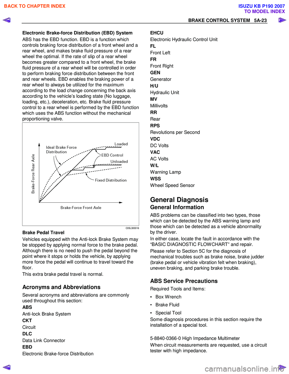
Electronic Brake-force Distribution (EBD) System
ABS has the EBD function. EBD is a function which
controls braking force distribution of a front wheel and a
rear wheel, and makes brake fluid pressure of a rear
wheel the optimal. If the rate of slip of a rear wheel
becomes greater compared to a front wheel, the brake
fluid pressure of a rear wheel will be controlled in order
to perform braking force distribution between the front
and rear wheels. EBD enables the braking power of a
rear wheel to always be utilized for the maximum
according to the load change concerning the back axis
according to the vehicle’s loading state (No luggage,
loading, etc.), deceleration, etc. Brake fluid pressure
control to a rear wheel is performed by the EBD function
which uses the ABS function without the mechanical
proportioning valve.
C05L300016
Brake Pedal Travel
Vehicles equipped with the Anti-lock Brake System may
be stopped by applying normal force to the brake pedal.
Although there is no need to push the pedal beyond the
point where it stops or holds the vehicle, by applying
more force the pedal will continue to travel toward the
floor.
This extra brake pedal travel is normal.
Acronyms and Abbreviations
Several acronyms and abbreviations are commonly
used throughout this section:
ABS
Anti-lock Brake System
CKT
Circuit
DLC
Data Link Connector
EBD
Electronic Brake-force Distribution
EHCU
Electronic Hydraulic Control Unit
FL
Front Left
FR
Front Right
GEN
Generator
H/U
Hydraulic Unit
MV
Millivolts
RR
Rear
RPS
Revolutions per Second
VDC
DC Volts
VAC
AC Volts
W/L
W arning Lamp
WSS
W heel Speed Sensor
General Diagnosis
General Information
ABS problems can be classified into two types, those
which can be detected by the ABS warning lamp and
those which can be detected as a vehicle abnormality
by the driver.
In either case, locate the fault in accordance with the
“BASIC DIAGNOSTIC FLOW CHART” and repair.
Please refer to Section 5C for the diagnosis of
mechanical troubles such as brake noise, brake judder
(brake pedal or vehicle vibration felt when braking),
uneven braking, and parking brake trouble.
ABS Service Precautions
Required Tools and Items:
• Box W rench
• Brake Fluid
• Special Tool
Some diagnosis procedures in this section require the
installation of a special tool.
5-8840-0366-0 High Impedance Multimeter
W hen circuit measurements are requested, use a circuit
tester with high impedance.
BACK TO CHAPTER INDEX
TO MODEL INDEX
ISUZU KB P190 2007
Page 617 of 6020
5A-24 BRAKE CONTROL SYSTEM
Computer System Service Precautions
The Anti-lock Brake System and Electronic Brake-force
Distribution interfaces directly with the Electronic
Hydraulic Control Unit (EHCU) which is a control
computer that is similar in some regards to the Engine
Control Module. These modules are designed to
withstand normal current draws associated with vehicle
operation. However, care must be taken to avoid
overloading any of the EHCU circuits. In testing for
opens or shorts, do not ground or apply voltage to any
of the circuits unless instructed to do so by the
appropriate diagnostic procedure. These circuits should
only be tested with a high impedance multimeter
5-8840-0366-0 or special tools as described in this
section. Power should never be removed or applied to
any control module with the ignition in the “ON” position.
Before removing or connecting battery cables, fuses or
connectors, always turn the ignition switch to the “OFF”
position.
General Service Precautions
The following are general precautions which should be
observed when servicing and diagnosing the Anti-lock
Brake System and/or other vehicle systems. Failure to
observe these precautions may result in Anti-lock Brake
System and Electronic Brake-force Distribution
damage.
• If welding work is to be performed on the vehicle using an electric arc welder, the EHCU and valve
block connectors should be disconnected before the
welding operation begins.
• The EHCU and valve block connectors should never be connected or disconnected with the
ignition “ON”.
Note:
• If only rear wheels are rotated using jacks or drum tester, the system will diagnose a speed sensor
malfunction and the “ABS and Brake” warning lamp
will illuminate. But actually no trouble exists. W hen
the DTC is not detected and the ABS and BRAKE
warning lamp is on, “How to erase code” is
performed and an ABS and BRAKE warning lamp
are off.
If the battery has been discharged
The engine may stall if the battery has been completely
discharged and the engine is started via jumper cables.
This is because the Anti-lock Brake System (ABS) and
Electronic Brake-force Distribution (EBD) System
requires a large quantity of electricity. In this case, wait
until the battery is recharged, or set the ABS and EBD
to a non-operative state by removing the fuse for the
ABS. After the battery has been recharged, stop the
engine and install the ABS fuse. Start the engine again,
and confirm that the ABS warning Lamp does not light.
Note on Intermittents
As with virtually any electronic system, it is difficult to
identify an intermittent failure. In such a case duplicating
the system malfunction during a test drive or a good
description of vehicle behavior from the customer may
be helpful in locating a “most likely” failed component or
circuit. The symptom diagnosis chart may also be
useful in isolating the failure. Most intermittent
problems are caused by faulty electrical connections or
wiring. W hen an intermittent failure is encountered,
check suspect circuits for:
• Suspected harness damage.
• Poor mating of connector halves or terminals not fully seated in the connector body (backed out).
• Improperly formed or damaged terminals.
Test Driving ABS Complaint Vehicles
If there has been an abnormality in the lighting pattern
of the “ABS” warning lamp, the fault can be located in
accordance with the “DIAGNOSIS BY “ABS” W ARNING
LAMP ILLUMINATION PATTERN”. Although such
problems can be detected by the driver as a vehicle
symptom, it is still necessary to perform a test drive
following the test procedure mentioned below, in order
to reproduce the symptom for problem diagnosis on a
symptom basis:
1. Start the engine and make sure that the “ABS” W /L
goes OFF. If the W /L remains ON, it means that
the Diagnostic Trouble Code (DTC) is stored.
Therefore, read the code and locate the fault.
Note: The DTC cannot be cleared if the vehicle speed
does not exceed about 10km/h (6mph) at DTC, even
though the repair operation is completed.
2. Start the vehicle and accelerate to about 30 km/h (19 mph) or more.
3. Slowly brake and stop the vehicle completely.
4. Then restart the vehicle and accelerate to about 40 km/h (25 mph) or more.
5. Brake at a time so as to actuate the ABS and stop the vehicle.
6. Be cautious of abnormality during the test. If the W /L is actuated while driving, read the DTC and
locate the fault.
7. If the abnormality is not reproduced by the test, make best efforts to reproduce the situation
reported by the customer.
8. If the abnormality has been detected, repair in accordance with the “SYMPTOM DIAGNOSIS”.
Note:
• Be sure to perform a test drive on a wide, even road
with light traffic.
• If an abnormality is detected, be sure to suspend the test and start trouble diagnosis at once.
BACK TO CHAPTER INDEX
TO MODEL INDEX
ISUZU KB P190 2007
Page 618 of 6020
BRAKE CONTROL SYSTEM 5A-25
“ABS” Warning Lamp
W hen ABS and problems occur that actuate the “ABS”
warning lamp, the code corresponding to the problem is
stored in the EHCU. Only ordinary braking is available
when the ABS is deactivated. Even when the “ABS”
warning lamp is actuated, if the starter switch is set ON
after setting it OFF once, the EHCU checks up on the
entire system. If there is no abnormality, the EHCU
judges ABS to work correctly and the warning lamp is lit
normally, even though the problem code is stored.
NOTE: Illumination of the “ABS” warning lamp indicates
that anti-lock braking is no longer available. Power
assisted braking without anti-lock control is still
available.
Normal Operation
“ABS ” Warning Lamp
W hen the ignition is first moved from “OFF” to “RUN”,
the amber “ABS” warning lamp will turn “ON”. The
“ABS” warning lamp will turn “ON” during engine
starting and will usually stay “ON” for approximately
three seconds after the ignition switch is returned to the
“ON” position. The warning lamp should remain “OFF”
at all other times.
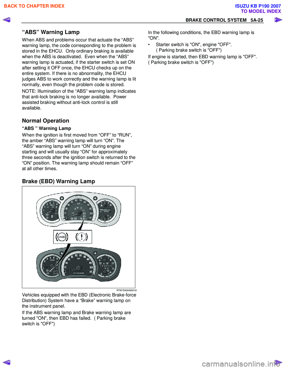
Brake (EBD) Warning Lamp
RTW 75ASH000101
Vehicles equipped with the EBD (Electronic Brake-force
Distribution) System have a “Brake” warning lamp on
the instrument panel.
If the ABS warning lamp and Brake warning lamp are
turned "ON", then EBD has failed. ( Parking brake
switch is "OFF")
In the following conditions, the EBD warning lamp is
"ON".
• Starter switch is "ON", engine "OFF". ( Parking brake switch is "OFF")
If engine is started, then EBD warning lamp is "OFF".
( Parking brake switch is "OFF")
BACK TO CHAPTER INDEX
TO MODEL INDEX
ISUZU KB P190 2007
Page 635 of 6020
5A-42 BRAKE CONTROL SYSTEM
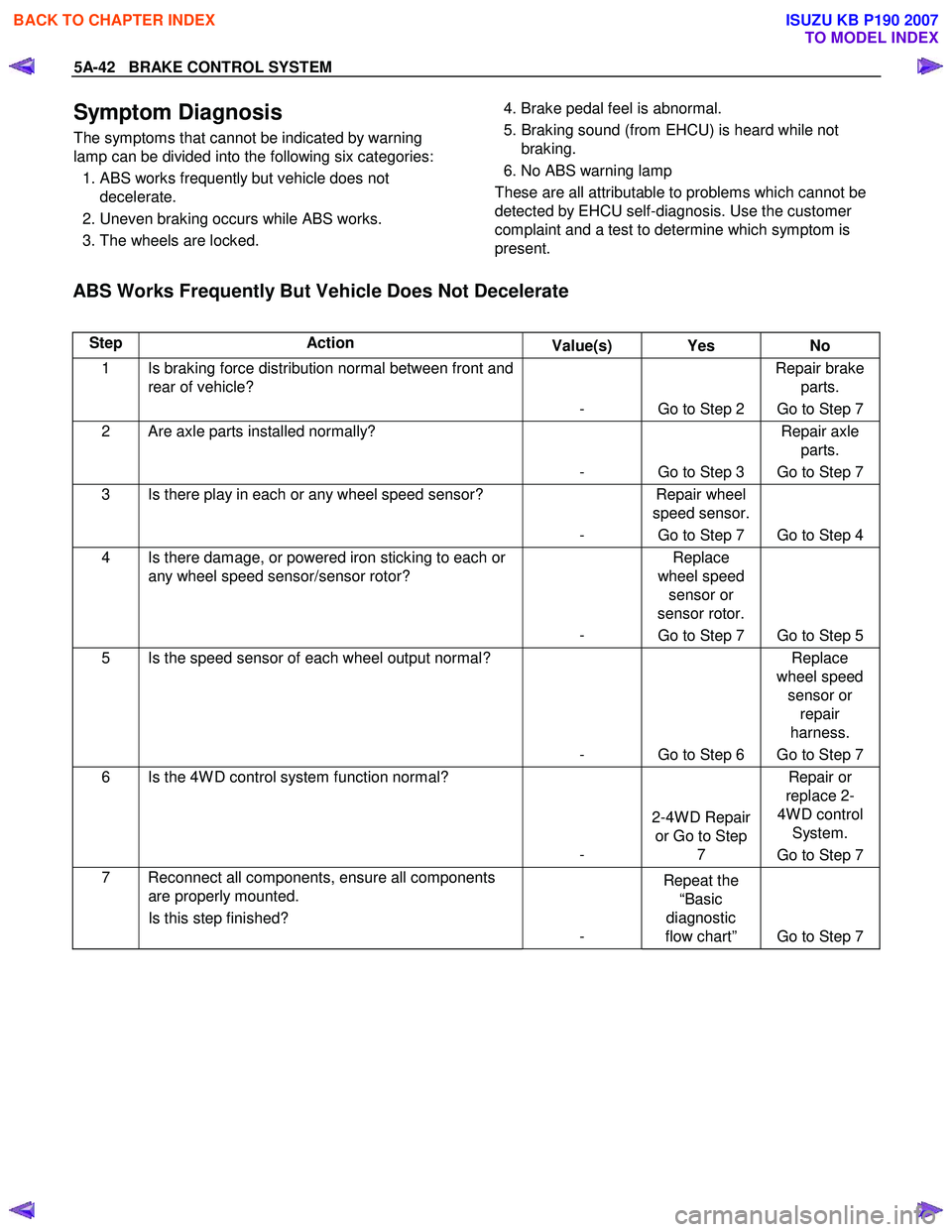
Symptom Diagnosis
The symptoms that cannot be indicated by warning
lamp can be divided into the following six categories:
1. ABS works frequently but vehicle does not decelerate.
2. Uneven braking occurs while ABS works.
3. The wheels are locked.
4. Brake pedal feel is abnormal.
5. Braking sound (from EHCU) is heard while not braking.
6. No ABS warning lamp
These are all attributable to problems which cannot be
detected by EHCU self-diagnosis. Use the customer
complaint and a test to determine which symptom is
present.
ABS Works Frequently But Vehicle Does Not Decelerate
Step Action Value(s) Yes No
1 Is braking force distribution normal between front and
rear of vehicle?
- Go to Step 2 Repair brake
parts.
Go to Step 7
2 Are axle parts installed normally?
- Go to Step 3 Repair axle
parts.
Go to Step 7
3 Is there play in each or any wheel speed sensor?
- Repair wheel
speed sensor.
Go to Step 7 Go to Step 4
4 Is there damage, or powered iron sticking to each or any wheel speed sensor/sensor rotor?
- Replace
wheel speed sensor or
sensor rotor.
Go to Step 7 Go to Step 5
5 Is the speed sensor of each wheel output normal?
- Go to Step 6 Replace
wheel speed sensor or repair
harness.
Go to Step 7
6 Is the 4W D control system function normal?
- 2-4W D Repair
or Go to Step 7 Repair or
replace 2-
4W D control System.
Go to Step 7
7 Reconnect all components, ensure all components are properly mounted.
Is this step finished? - Repeat the
“Basic
diagnostic
flow chart” Go to Step 7
BACK TO CHAPTER INDEX
TO MODEL INDEX
ISUZU KB P190 2007
Page 1041 of 6020
Engine Control System (4JH1) 6E-7
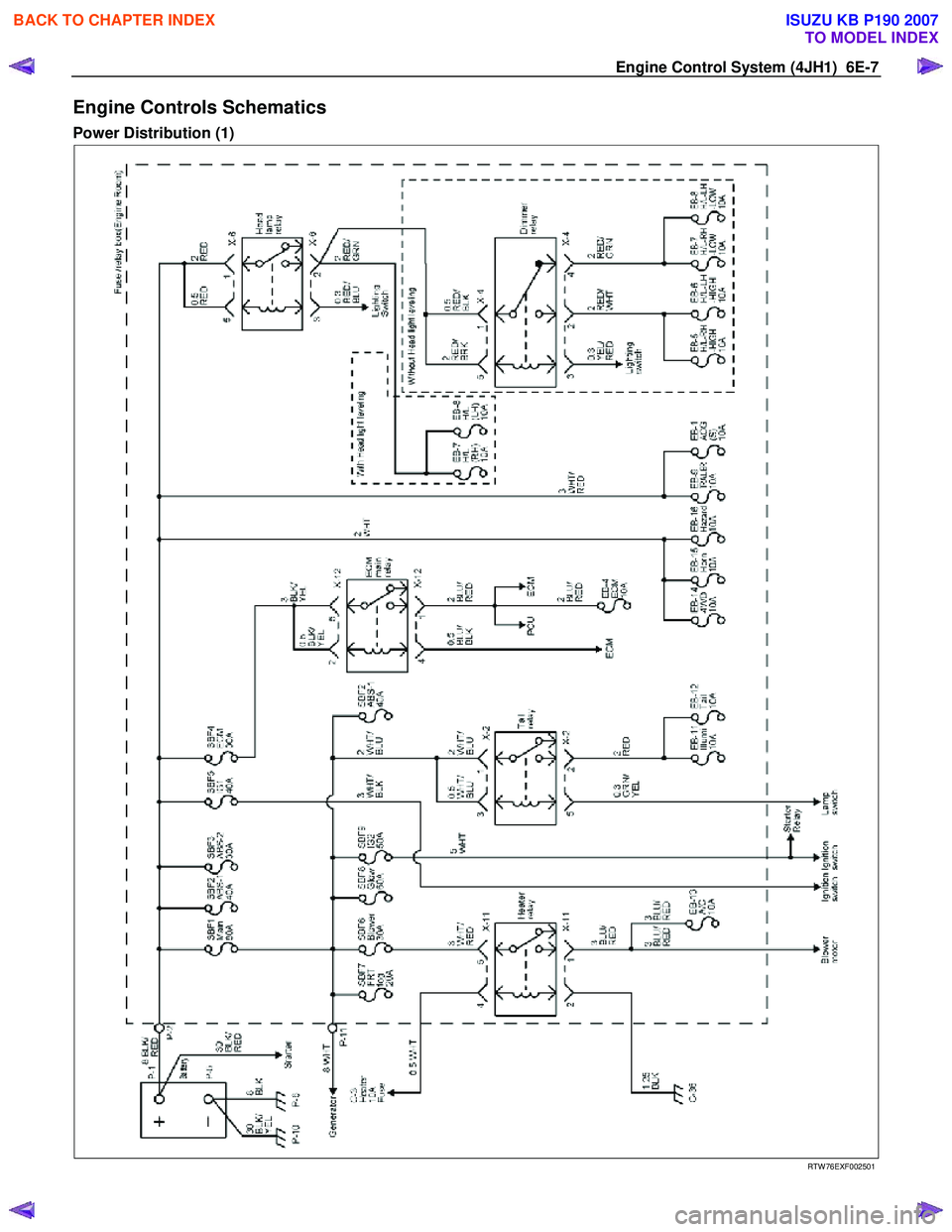
Engine Controls Schematics
Power Distribution (1)
RTW 76EXF002501
BACK TO CHAPTER INDEX
TO MODEL INDEX
ISUZU KB P190 2007
Page 1042 of 6020
6E-8 Engine Control System (4JH1)
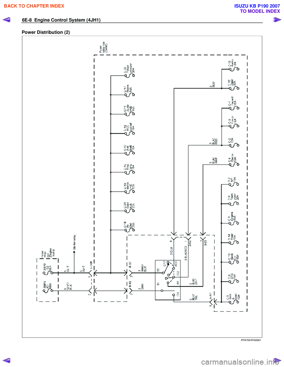
Power Distribution (2)
RTW 76EXF002601
BACK TO CHAPTER INDEX
TO MODEL INDEX
ISUZU KB P190 2007
Page 1323 of 6020
Engine Control System (4JH1) 6E-289
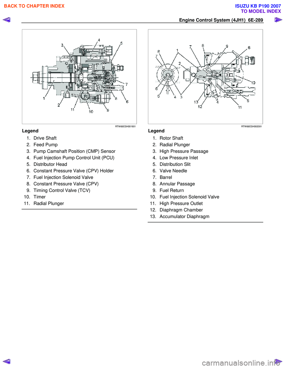
RTW 66ESH001901
Legend
1. Drive Shaft
2. Feed Pump
3. Pump Camshaft Position (CMP) Sensor
4. Fuel Injection Pump Control Unit (PCU)
5. Distributor Head
6. Constant Pressure Valve (CPV) Holder
7. Fuel Injection Solenoid Valve
8. Constant Pressure Valve (CPV)
9. Timing Control Valve (TCV)
10. Timer
11. Radial Plunger
RTW 66ESH002001
Legend
1. Rotor Shaft
2. Radial Plunger
3. High Pressure Passage
4. Low Pressure Inlet
5. Distribution Slit
6. Valve Needle
7. Barrel
8. Annular Passage
9. Fuel Return
10. Fuel Injection Solenoid Valve
11. High Pressure Outlet
12. Diaphragm Chamber
13. Accumulator Diaphragm
BACK TO CHAPTER INDEX
TO MODEL INDEX
ISUZU KB P190 2007
Page 1325 of 6020
Engine Control System (4JH1) 6E-291
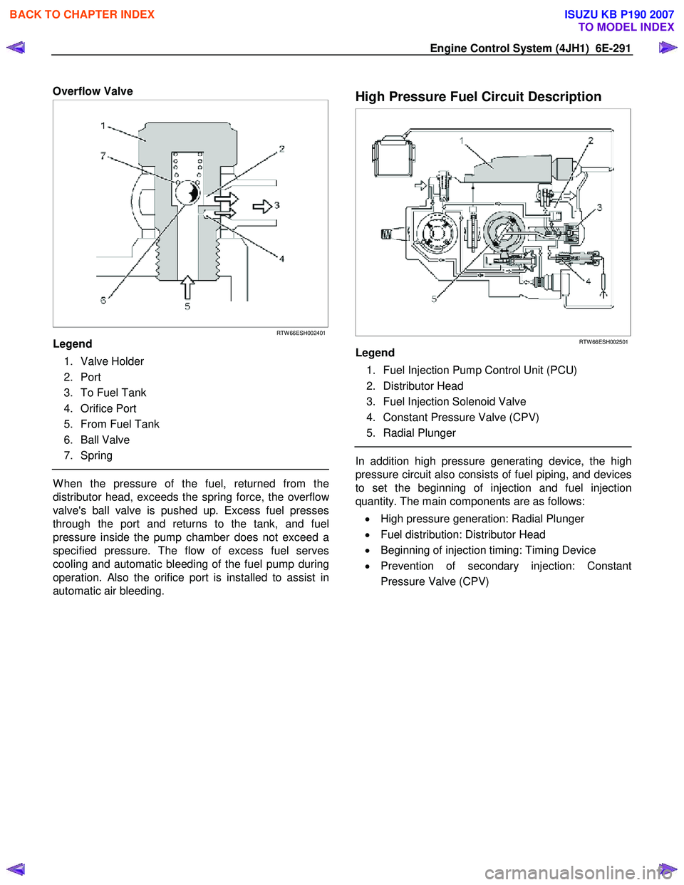
Overflow Valve
RTW 66ESH002401
Legend
1. Valve Holder
2. Port
3. To Fuel Tank
4. Orifice Port
5. From Fuel Tank
6. Ball Valve
7. Spring
W hen the pressure of the fuel, returned from the
distributor head, exceeds the spring force, the overflo
w
valve's ball valve is pushed up. Excess fuel presses
through the port and returns to the tank, and fuel
pressure inside the pump chamber does not exceed a
specified pressure. The flow of excess fuel serves
cooling and automatic bleeding of the fuel pump during
operation. Also the orifice port is installed to assist in
automatic air bleeding.
High Pressure Fuel Circuit Description
RTW 66ESH002501
Legend
1. Fuel Injection Pump Control Unit (PCU)
2. Distributor Head
3. Fuel Injection Solenoid Valve
4. Constant Pressure Valve (CPV)
5. Radial Plunger
In addition high pressure generating device, the high
pressure circuit also consists of fuel piping, and devices
to set the beginning of injection and fuel injection
quantity. The main components are as follows:
• High pressure generation: Radial Plunger
• Fuel distribution: Distributor Head
• Beginning of injection timing: Timing Device
• Prevention of secondary injection: Constant
Pressure Valve (CPV)
BACK TO CHAPTER INDEX
TO MODEL INDEX
ISUZU KB P190 2007