automatic transmission fluid ISUZU KB P190 2007 Workshop Repair Manual
[x] Cancel search | Manufacturer: ISUZU, Model Year: 2007, Model line: KB P190, Model: ISUZU KB P190 2007Pages: 6020, PDF Size: 70.23 MB
Page 21 of 6020
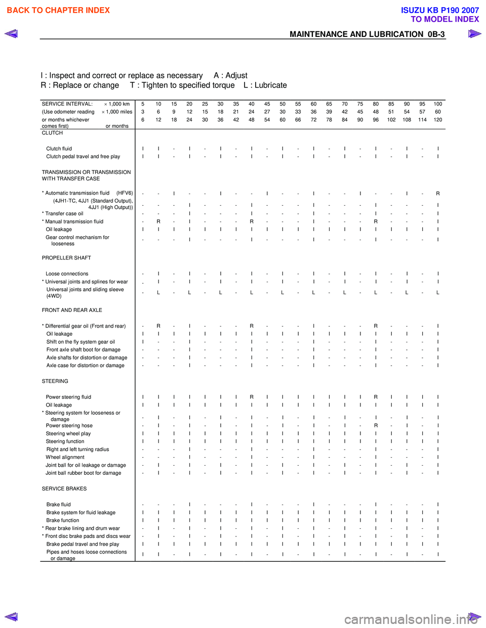
MAINTENANCE AND LUBRICATION 0B-3
I : Inspect and correct or replace as necessary A : Adjust
R : Replace or change T : Tighten to specified torque L : Lubricate
SERVICE INTERVAL: × 1,000 km 5 10 15 20 25 30 35 40 45 50 55 60 65 70 75 80 85 90 95 100(Use odometer reading × 1,000 miles 3 6 9 12 15 18 21 24 27 30 33 36 39 42 45 48 51 54 57 60or months whichever
comes first)
or months 6 12 18 24 30 36 42 48 54 60 66 72 78 84 90 96 102 108 114 120
CLUTCH
Clutch fluid I I - I - I - I - I - I - I - I - I - I Clutch pedal travel and free play I I - I - I - I - I - I - I - I - I - I TRANSMISSION OR TRANSMISSION
W ITH TRANSFER CASE
* Automatic transmission fluid (HFV6)
- - I - - I - - I - - I - - I - - I - R (4JH1-TC, 4JJ1 (Standard Output),
4JJ1 (High Output)) - - - I - - - I - - - I - - - I - - - I
* Transfer case oil
- - - I - - - I - - - I - - - I - - - I * Manual transmission fluid - R - I - - - R - - - I - - - R - - - I Oil leakage I I I I I I I I I I I I I I I I I I I I Gear control mechanism for
looseness - - - I - - - I - - - I - - - I - - - I
PROPELLER SHAFT Loose connections - I - I - I - I - I - I - I - I - I - I * Universal joints and splines for wear
- I - I - I - I - I - I - I - I - I - I Universal joints and sliding sleeve
(4W D) - L - L - L - L - L - L - L - L - L - L
FRONT AND REAR AXLE * Differential gear oil (Front and rear) - R - I - - - R - - - I - - - R - - - I Oil leakage I I I I I I I I I I I I I I I I I I I I Shift on the fly system gear oil I - - I - - - I - - - I - - - I - - - I Front axle shaft boot for damage - - - I - - - I - - - I - - - I - - - I Axle shafts for distortion or damage - - - I - - - I - - - I - - - I - - - I Axle case for distortion or damage - - - I - - - I - - - I - - - I - - - I STEERING Power steering fluid I I I I I I I R I I I I I I I R I I I I Oil leakage I I I I I I I I I I I I I I I I I I I I * Steering system for looseness or
damage - I - I - I - I - I - I - I - I - I - I
Power steering hose
- I - I - I - I - I - I - I - R - I - I Steering wheel play I I I I I I I I I I I I I I I I I I I I Steering function I I I I I I I I I I I I I I I I I I I I Right and left turning radius - - - I - - - I - - - I - - - I - - - I W heel alignment - - - I - - - I - - - I - - - I - - - I Joint ball for oil leakage or damage - I - I - I - I - I - I - I - I - I - I Joint ball rubber boot for damage - I - I - I - I - I - I - I - I - I - I SERVICE BRAKES Brake fluid - - - I - - - I - - - I - - - I - - - I Brake system for fluid leakage I I I I I I I I I I I I I I I I I I I I Brake function I I I I I I I I I I I I I I I I I I I I * Rear brake lining and drum wear - I - I - I - I - I - I - I - I - I - I * Front disc brake pads and discs wear - I - I - I - I - I - I - I - I - I - I Brake pedal travel and free play I I I I I I I I I I I I I I I I I I I I Pipes and hoses loose connections
or damage I I - I - I - I - I - I - I - I - I - I
BACK TO CHAPTER INDEX
TO MODEL INDEX
ISUZU KB P190 2007
Page 23 of 6020
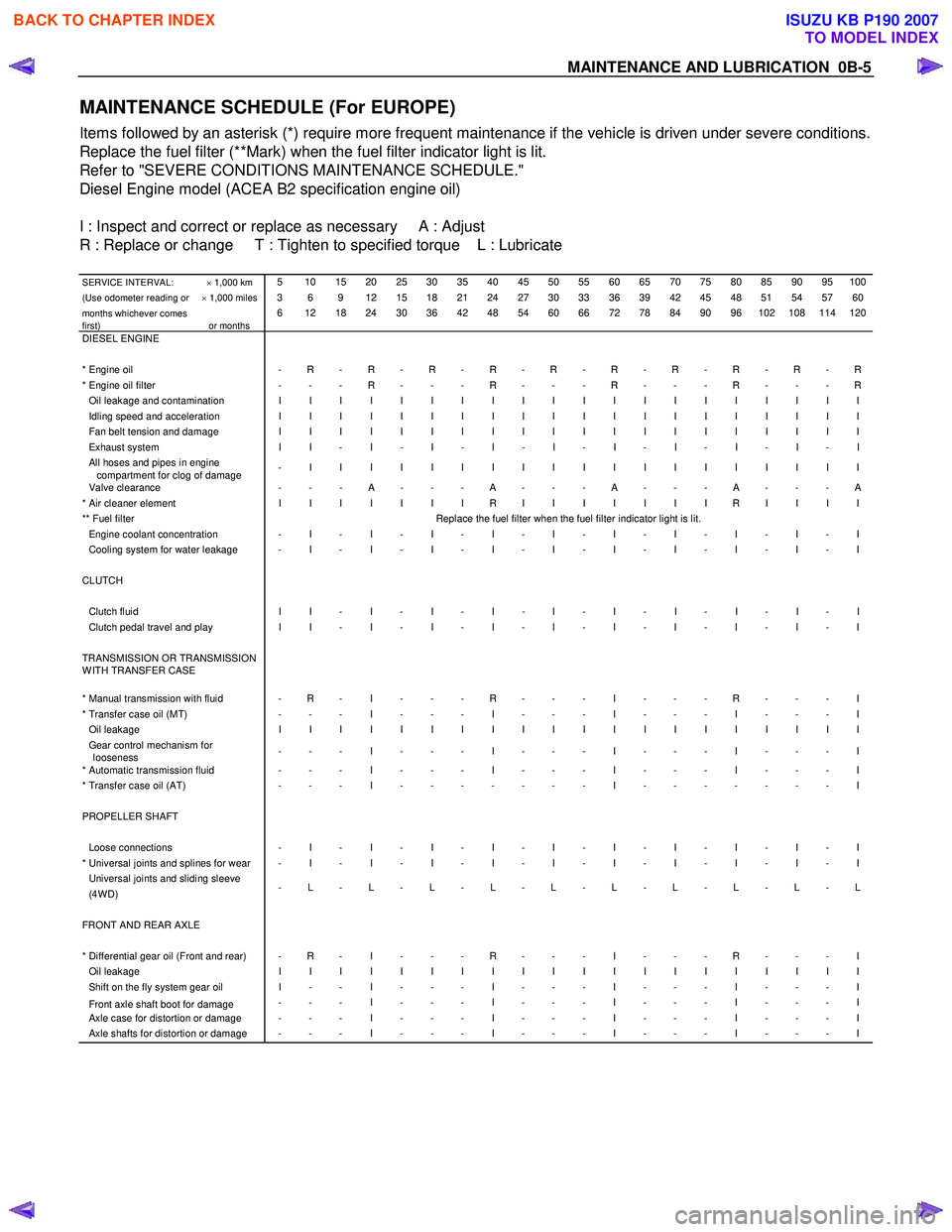
MAINTENANCE AND LUBRICATION 0B-5
MAINTENANCE SCHEDULE (For EUROPE)
Items followed by an asterisk (*) require more frequent maintenance if the vehicle is driven under severe conditions.
Replace the fuel filter (**Mark) when the fuel filter indicator light is lit.
Refer to "SEVERE CONDITIONS MAINTENANCE SCHEDULE."
Diesel Engine model (ACEA B2 specification engine oil)
I : Inspect and correct or replace as necessary A : Adjust
R : Replace or change T : Tighten to specified torque L : Lubricate
SERVICE INTERVAL: × 1,000 km 5 10 15 20 25 30 35 40 45 50 55 60 65 70 75 80 85 90 95 100
(Use odometer reading or × 1,000 miles 3 6 9 12 15 18 21 24 27 30 33 36 39 42 45 48 51 54 57 60
months whichever comes
first)
or months 6 12 18 24 30 36 42 48 54 60 66 72 78 84 90 96 102 108 114 120
DIESEL ENGINE * Engine oil - R - R - R - R - R - R - R - R - R - R* Engine oil filter - - - R - - - R - - - R - - - R - - - ROil leakage and contamination I I I I I I I I I I I I I I I I I I I I Idling speed and acceleration I I I I I I I I I I I I I I I I I I I I Fan belt tension and damage I I I I I I I I I I I I I I I I I I I I Exhaust system I I - I - I - I - I - I - I - I - I - I All hoses and pipes in engine
compartment for clog of damage - I I I I I I I I I I I I I I I I I I I
Valve clearance
- - - A - - - A - - - A - - - A - - - A * Air cleaner element I I I I I I I R I I I I I I I R I I I I ** Fuel filter Replace the fuel filter when the fuel filter indicator light is lit. Engine coolant concentration - I - I - I - I - I - I - I - I - I - I Cooling system for water leakage - I - I - I - I - I - I - I - I - I - I CLUTCH Clutch fluid I I - I - I - I - I - I - I - I - I - I Clutch pedal travel and play I I - I - I - I - I - I - I - I - I - I TRANSMISSION OR TRANSMISSION
W ITH TRANSFER CASE
* Manual transmission with fluid - R - I - - - R - - - I - - - R - - - I * Transfer case oil (MT) - - - I - - - I - - - I - - - I - - - I Oil leakage I I I I I I I I I I I I I I I I I I I I Gear control mechanism for
looseness - - - I - - - I - - - I - - - I - - - I
* Automatic transmission fluid - - - I - - - I - - - I - - - I - - - I * Transfer case oil (AT)
- - - I - - - - - - - I - - - - - - - I PROPELLER SHAFT Loose connections - I - I - I - I - I - I - I - I - I - I * Universal joints and splines for wear - I - I - I - I - I - I - I - I - I - I Universal joints and sliding sleeve (4W D) - L - L - L - L - L - L - L - L - L - L
FRONT AND REAR AXLE * Differential gear oil (Front and rear) - R - I - - - R - - - I - - - R - - - I Oil leakage I I I I I I I I I I I I I I I I I I I I Shift on the fly system gear oil I - - I - - - I - - - I - - - I - - - I
Front axle shaft boot for damage - - - I - - - I - - - I - - - I - - - I Axle case for distortion or damage - - - I - - - I - - - I - - - I - - - I Axle shafts for distortion or damage - - - I - - - I - - - I - - - I - - - I
BACK TO CHAPTER INDEX
TO MODEL INDEX
ISUZU KB P190 2007
Page 25 of 6020
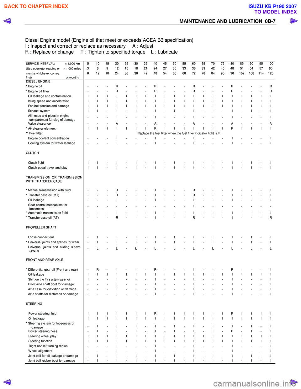
MAINTENANCE AND LUBRICATION 0B-7
Diesel Engine model (Engine oil that meet or exceeds ACEA B3 specification)
I : Inspect and correct or replace as necessary A : Adjust
R : Replace or change T : Tighten to specified torque L : Lubricate
SERVICE INTERVAL: × 1,000 km 5 10 15 20 25 30 35 40 45 50 55 60 65 70 75 80 85 90 95 100
(Use odometer reading or × 1,000 miles 3 6 9 12 15 18 21 24 27 30 33 36 39 42 45 48 51 54 57 60
months whichever comes
first)
or months 6 12 18 24 30 36 42 48 54 60 66 72 78 84 90 96 102 108 114 120
DIESEL ENGINE * Engine oil - - - R - - - R - - - R - - - R - - - R*
Engine oil filter
- - - R - - - R - - - R - - - R - - - R
Oil leakage and contamination I I I I I I I I I I I I I I I I I I I I Idling speed and acceleration I I I I I I I I I I I I I I I I I I I I Fan belt tension and damage I I I I I I I I I I I I I I I I I I I I Exhaust system I I - I - I - I - I - I - I - I - I - I All hoses and pipes in engine
compartment for clog of damage - - - I - - - I - - - I - - - I - - - I
Valve clearance
- - - A - - - A - - - A - - - A - - - A * Air cleaner element I I I I I I I R I I I I I I I R I I I I ** Fuel filter Replace the fuel filter when the fuel filter indicator light is lit. Engine coolant concentration - - - I - - - I - - - I - - - I - - - I Cooling system for water leakage - - - I - - - I - - - I - - - I - - - I CLUTCH Clutch fluid I I - I - I - I - I - I - I - I - I - I Clutch pedal travel and play I I - I - I - I - I - I - I - I - I - I TRANSMISSION OR TRANSMISSION
W ITH TRANSFER CASE
* Manual transmission with fluid - - - R - - - I - - - R - - - I - - - I * Transfer case oil (MT) - - - R - - - I - - - R - - - I - - - I Oil leakage - - - I - - - I - - - I - - - I - - - I Gear control mechanism for
looseness - - - - - - - - - - - I - - - - - - - -
* Automatic transmission fluid - - - I - - - I - - - I - - - I - - - I * Transfer case oil (AT)
- - - R - - - I - - - R - - - I - - - R PROPELLER SHAFT Loose connections - I - I - I - I - I - I - I - I - I - I * Universal joints and splines for wear - I - I - I - I - I - I - I - I - I - I Universal joints and sliding sleeve
(4W D) - L - L - L - L - L - L - L - L - L - L
FRONT AND REAR AXLE
* Differential gear oil (Front and rear) - R - I - - - R - - - I - - - R - - - I Oil leakage I I I I I I I I I I I I I I I I I I I I Shift on the fly system gear oil I - - I - - - I - - - I - - - I - - - I Front axle shaft boot for damage - - - I - - - I - - - I - - - I - - - I Axle case for distortion or damage - - - I - - - I - - - I - - - I - - - I Axle shafts for distortion or damage - - - I - - - I - - - I - - - I - - - I STEERING Power steering fluid I I I I I I I R I I I I I I I R I I I I Oil leakage I I I I I I I I I I I I I I I I I I I I * Steering system for looseness or
damage - I - I - I - I - I - I - I - I - I - I
Power steering hose
- I - I - I - I - I - I - I - R - I - I Steering wheel play I I I I I I I I I I I I I I I I I I I I Steering function I I I I I I I I I I I I I I I I I I I I Right and left turning radius - - - I - - - I - - - I - - - I - - - I W heel alignment - - - I - - - I - - - I - - - I - - - I Joint ball for oil leakage or damage - I - I - I - I - I - I - I - I - I - I Joint ball rubber boot for damage - I - I - I - I - I - I - I - I - I - I
BACK TO CHAPTER INDEX
TO MODEL INDEX
ISUZU KB P190 2007
Page 29 of 6020
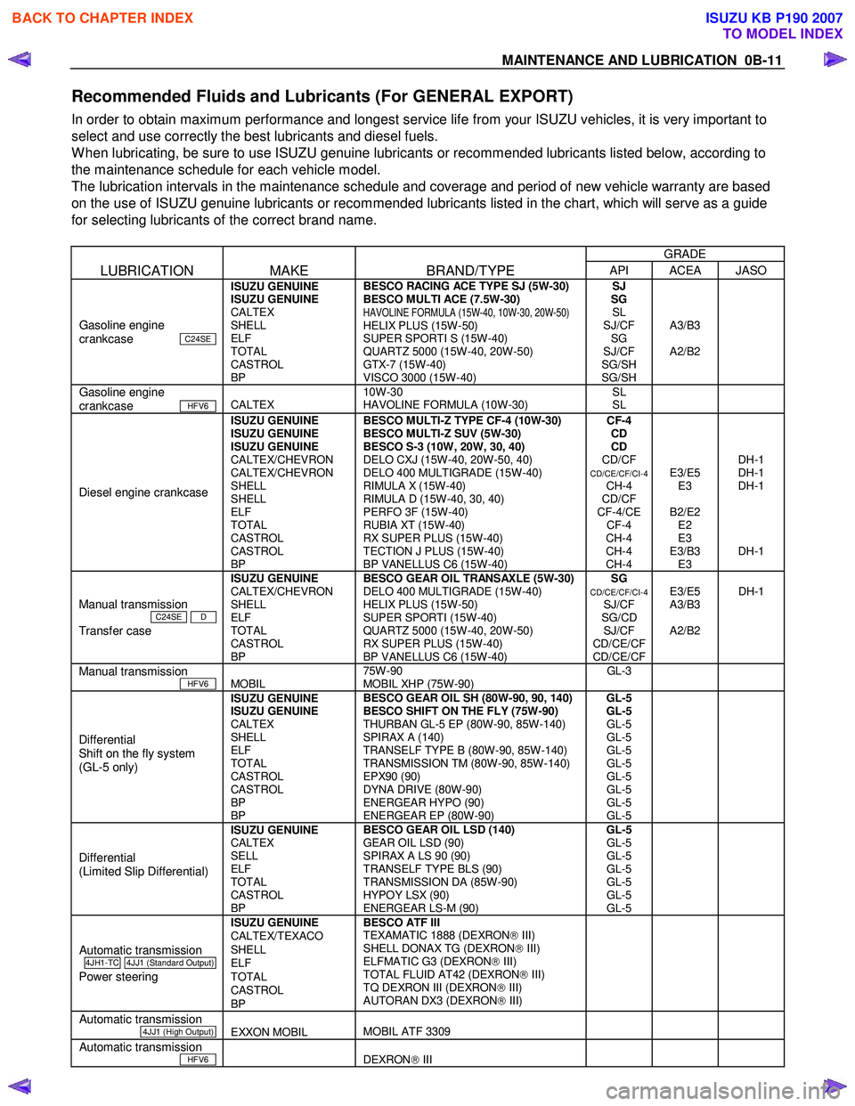
MAINTENANCE AND LUBRICATION 0B-11
Recommended Fluids and Lubricants (For GENERAL EXPORT)
In order to obtain maximum performance and longest service life from your ISUZU vehicles, it is very important to
select and use correctly the best lubricants and diesel fuels.
W hen lubricating, be sure to use ISUZU genuine lubricants or recommended lubricants listed below, according to
the maintenance schedule for each vehicle model.
The lubrication intervals in the maintenance schedule and coverage and period of new vehicle warranty are based
on the use of ISUZU genuine lubricants or recommended lubricants listed in the chart, which will serve as a guide
for selecting lubricants of the correct brand name.
GRADE
LUBRICATION MAKE BRAND/TYPE API ACEA JASO
Gasoline engine
crankcase C24SE
ISUZU GENUINE
ISUZU GENUINE
CALTEX
SHELL
ELF
TOTAL
CASTROL
BP BESCO RACING ACE TYPE SJ (5W-30)
BESCO MULTI ACE (7.5W-30)
HAVOLINE FORMULA (15W-40, 10W-30, 20W-50) HELIX PLUS (15W-50)
SUPER SPORTI S (15W-40)
QUARTZ 5000 (15W-40, 20W-50)
GTX-7 (15W-40)
VISCO 3000 (15W-40) SJ
SG SL
SJ/CF SG
SJ/CF
SG/SH
SG/SH
A3/B3
A2/B2
Gasoline engine
crankcase HFV6
CALTEX 10W-30
HAVOLINE FORMULA (10W-30) SL
SL
Diesel engine crankcase
ISUZU GENUINE
ISUZU GENUINE
ISUZU GENUINE
CALTEX/CHEVRON
CALTEX/CHEVRON
SHELL
SHELL
ELF
TOTAL
CASTROL
CASTROL
BP BESCO MULTI-Z TYPE CF-4 (10W-30)
BESCO MULTI-Z SUV (5W-30)
BESCO S-3 (10W, 20W, 30, 40)
DELO CXJ (15W-40, 20W-50, 40)
DELO 400 MULTIGRADE (15W-40)
RIMULA X (15W-40)
RIMULA D (15W-40, 30, 40)
PERFO 3F (15W-40)
RUBIA XT (15W-40)
RX SUPER PLUS (15W-40)
TECTION J PLUS (15W-40)
BP VANELLUS C6 (15W-40) CF-4
CD
CD
CD/CF
CD/CE/CF/CI-4 CH-4
CD/CF
CF-4/CE CF-4
CH-4
CH-4
CH-4
E3/E5 E3
B2/E2 E2
E3
E3/B3 E3
DH-1
DH-1
DH-1
DH-1
Manual transmission
C24SE D
Transfer case
ISUZU GENUINE
CALTEX/CHEVRON
SHELL
ELF
TOTAL
CASTROL
BP
BESCO GEAR OIL TRANSAXLE (5W-30)
DELO 400 MULTIGRADE (15W-40)
HELIX PLUS (15W-50)
SUPER SPORTI (15W-40)
QUARTZ 5000 (15W-40, 20W-50)
RX SUPER PLUS (15W-40)
BP VANELLUS C6 (15W-40)
SG CD/CE/CF/CI-4 SJ/CF
SG/CD SJ/CF
CD/CE/CF
CD/CE/CF
E3/E5
A3/B3
A2/B2
DH-1
Manual transmission
HFV6
MOBIL 75W-90
MOBIL XHP (75W-90) GL-3
Differential
Shift on the fly system
(GL-5 only) ISUZU GENUINE
ISUZU GENUINE
CALTEX
SHELL
ELF
TOTAL
CASTROL
CASTROL
BP
BP BESCO GEAR OIL SH (80W-90, 90, 140)
BESCO SHIFT ON THE FLY (75W-90)
THURBAN GL-5 EP (80W-90, 85W-140)
SPIRAX A (140)
TRANSELF TYPE B (80W-90, 85W-140)
TRANSMISSION TM (80W-90, 85W-140)
EPX90 (90)
DYNA DRIVE (80W-90)
ENERGEAR HYPO (90)
ENERGEAR EP (80W-90) GL-5
GL-5 GL-5
GL-5
GL-5
GL-5
GL-5
GL-5
GL-5
GL-5
Differential
(Limited Slip Differential) ISUZU GENUINE
CALTEX
SELL
ELF
TOTAL
CASTROL
BP BESCO GEAR OIL LSD (140)
GEAR OIL LSD (90)
SPIRAX A LS 90 (90)
TRANSELF TYPE BLS (90)
TRANSMISSION DA (85W-90)
HYPOY LSX (90)
ENERGEAR LS-M (90) GL-5
GL-5
GL-5
GL-5
GL-5
GL-5
GL-5
Automatic transmission
4JH1-TC 4JJ1 (Standard Output)
Power steering
ISUZU GENUINE
CALTEX/TEXACO
SHELL
ELF
TOTAL
CASTROL
BP BESCO ATF III
TEXAMATIC 1888 (DEXRON III)
SHELL DONAX TG (DEXRON III)
ELFMATIC G3 (DEXRON III)
TOTAL FLUID AT42 (DEXRON III)
TQ DEXRON III (DEXRON III)
AUTORAN DX3 (DEXRON III)
Automatic transmission
4JJ1 (High Output)
EXXON MOBIL
MOBIL ATF 3309
Automatic transmission
HFV6
DEXRON III
BACK TO CHAPTER INDEX
TO MODEL INDEX
ISUZU KB P190 2007
Page 31 of 6020
MAINTENANCE AND LUBRICATION 0B-13
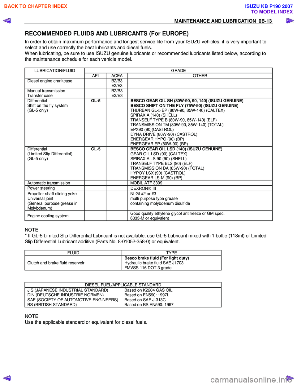
RECOMMENDED FLUIDS AND LUBRICANTS (For EUROPE)
In order to obtain maximum performance and longest service life from your ISUZU vehicles, it is very important to
select and use correctly the best lubricants and diesel fuels.
W hen lubricating, be sure to use ISUZU genuine lubricants or recommended lubricants listed below, according to
the maintenance schedule for each vehicle model.
LUBRICATION/FLUID GRADE
API ACEA OTHER
Diesel engine crankcase B2/B3
E2/E3
Manual transmission
Transfer case B2/B3
E2/E3
Differential
Shift on the fly system
(GL-5 only)
GL-5
BESCO GEAR OIL SH (80W-90, 90, 140) (ISUZU GENUINE)
BESCO SHIFT ON THE FLY (75W-90) (ISUZU GENUINE)
THURBAN GL-5 EP (80W-90, 85W-140) (CALTEX)
SPIRAX A (140) (SHELL)
TRANSELF TYPE B (80W-90, 85W-140) (ELF)
TRANSMISSION TM (80W-90, 85W-140) (TOTAL)
EPX90 (90)(CASTROL)
DYNA DRIVE (80W-90) (CASTROL)
ENERGEAR HYPO (90) (BP)
ENERGEAR EP (80W-90) (BP)
Differential
(Limited Slip Differential)
(GL-5 only) GL-5
BESCO GEAR OIL LSD (140) (ISUZU GENUINE)
GEAR OIL LSD (90) (CALTEX)
SPIRAX A LS 90 (90) (SHELL)
TRANSELF TYPE BLS (90) (ELF)
TRANSMISSION DA (85W-90) (TOTAL)
HYPOY LSX (90) (CASTROL)
ENERGEAR LS-M (90) (BP)
Automatic transmission MOBIL ATF 3309
Power steering
DEXRON III
Propeller shaft sliding yoke
Universal joint
(General purpose grease in
Molybdenum) NLGI #2 or #3
multi purpose type grease
containing molybdenum disulfide
Engine cooling system Good quality ethylene glycol antifreeze or GM spec.
6033-M or equivalent
NOTE:
* If GL-5 Limited Slip Differential Lubricant is not available, use GL-5 Lubricant mixed with 1 bottle (118ml) of Limited
Slip Differential Lubricant additive (Parts No. 8-01052-358-0) or equivalent.
FLUID TYPE
Clutch and brake fluid reservoir Besco brake fluid (For light duty)
Hydraulic brake fluid SAE J1703
FMVSS 116 DOT.3 grade
DIESEL FUEL/APPLICABLE STANDARD
JIS (JAPANESE INDUSTRIAL STANDARD)
DIN (DEUTSCHE INDUSTRIE NORMEN)
SAE (SOCIETY OF AUTOMOTIVE ENGINEERS)
BS (BRITISH STANDARD) Based on K2204 GAS OIL
Based on EN590: 1997L
Based on SAE J-313C
Based on BS EN590: 1997
NOTE:
Use the applicable standard or equivalent for diesel fuels.
BACK TO CHAPTER INDEX
TO MODEL INDEX
ISUZU KB P190 2007
Page 2677 of 6020
Engine Mechanical – V6 Page 6A1–198
k Timing chains, tensioners, shoes, guides & sprockets, refer to 3.16 Timing Chains, Tensioners, Shoes and
Guides.
l Cylinder head assemblies, refer to 3.22 Cylinder Head Assembly.
m Oil pan assembly, refer to 4.2 Oil Pan and Oil Pump Suction Pipe Assembly.
n Piston and connecting rod assemblies, refer to 4.5 Pistons, Pins, Rings, Connecting Rods and Big-end Bearings.
o Crankshaft assembly, refer to 4.6 Crankshaft and Main Bearings.
p Piston oil nozzles, refer 4.5 Pistons, Pins, Rings, Connecting Rods and Big-end Bearings.
Reassemble
Reassembly of the engine assembly is the reverse of the disassembly procedure.
Reinstall
Reinstallation of the engine assembly is the reverse to the removal procedure, noting the following:
NOTE
Refer to 6 Torque Wrench Specifications
for the correct torque specifications.
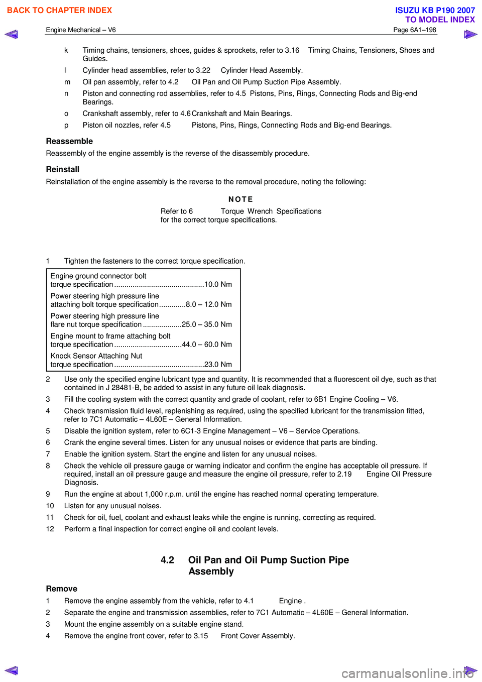
1 Tighten the fasteners to the correct torque specification.
Engine ground connector bolt
torque specification ............................................10.0 Nm
Power steering high pressure line
attaching bolt torque specification .............8.0 – 12.0 Nm
Power steering high pressure line
flare nut torque specification ...................25.0 – 35.0 Nm
Engine mount to frame attaching bolt
torque specification .................................44.0 – 60.0 Nm
Knock Sensor Attaching Nut
torque specification ............................................23.0 Nm
2 Use only the specified engine lubricant type and quantity. It is recommended that a fluorescent oil dye, such as that contained in J 28481-B, be added to assist in any future oil leak diagnosis.
3 Fill the cooling system with the correct quantity and grade of coolant, refer to 6B1 Engine Cooling – V6.
4 Check transmission fluid level, replenishing as required, using the specified lubricant for the transmission fitted, refer to 7C1 Automatic – 4L60E – General Information.
5 Disable the ignition system, refer to 6C1-3 Engine Management – V6 – Service Operations.
6 Crank the engine several times. Listen for any unusual noises or evidence that parts are binding.
7 Enable the ignition system. Start the engine and listen for any unusual noises.
8 Check the vehicle oil pressure gauge or warning indicator and confirm the engine has acceptable oil pressure. If required, install an oil pressure gauge and measure the engine oil pressure, refer to 2.19 Engine Oil Pressure
Diagnosis.
9 Run the engine at about 1,000 r.p.m. until the engine has reached normal operating temperature.
10 Listen for any unusual noises.
11 Check for oil, fuel, coolant and exhaust leaks while the engine is running, correcting as required.
12 Perform a final inspection for correct engine oil and coolant levels.
4.2 Oil Pan and Oil Pump Suction Pipe Assembly
Remove
1 Remove the engine assembly from the vehicle, refer to 4.1 Engine .
2 Separate the engine and transmission assemblies, refer to 7C1 Automatic – 4L60E – General Information.
3 Mount the engine assembly on a suitable engine stand.
4 Remove the engine front cover, refer to 3.15 Front Cover Assembly.
BACK TO CHAPTER INDEX
TO MODEL INDEX
ISUZU KB P190 2007
Page 3030 of 6020
Engine Mechanical – V6 Page 6A1–253
Page 6A1–253
k Timing chains, tensioners, shoes, guides & sprockets, refer to 3.16 Timing Chains, Tensioners, Shoes and
Guides .
l Cylinder head assemblies, refer to 3.22 Cylinder Head Assembly.
m Oil pan assembly, refer to 4.2 Oil Pan and Oil Pump Suction Pipe Assembly .
n Piston and connecting rod assemblies, refer to 4.5 Pistons, Pins, Rings, Connecting Rods and Big-end
Bearings .
o Crankshaft assembly, refer to 4.6 Crankshaft and Main Bearings.
p Piston oil nozzles, refer 4.5 Pistons, Pins, Rings, Connecting Rods and Big-end Bearings .
Reassemble
Reassembly of the engine assembly is the reverse of the disassembly procedure.
Reinstall
Reinstallation of the engine assembly is the revers e to the removal procedure, noting the following:
NOTE
Refer to 6 Torque Wrench Specifications for the
correct torque specifications.
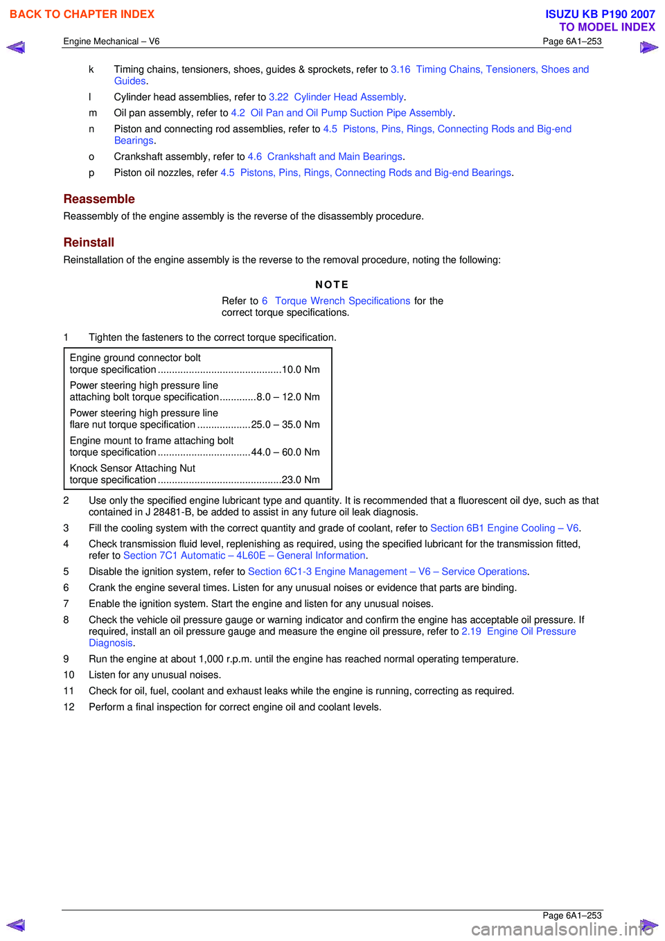
1 Tighten the fasteners to the co rrect torque specification.
Engine ground connector bolt
torque specificat ion ............................................ 10.0 Nm
Power steering high pressure line
attaching bolt torque specification ............. 8.0 – 12.0 Nm
Power steering high pressure line
flare nut torque specif ication ................... 25. 0 – 35.0 Nm
Engine mount to frame attaching bolt
torque specification ................................. 44. 0 – 60.0 Nm
Knock Sensor Attaching Nut
torque specification ............................................ 23.0 Nm
2 Use only the specified engine lubricant type and quantity. It is recommended that a fluorescent oil dye, such as that
contained in J 28481-B, be added to assist in any future oil leak diagnosis.
3 Fill the cooling system with the corre ct quantity and grade of coolant, refer to Section 6B1 Engine Cooling – V6.
4 Check transmission fluid level, replenishing as required, using the specified lubricant for the transmission fitted,
refer to Section 7C1 Automatic – 4L60E – General Information .
5 Disable the ignition system, refer to Section 6C1-3 Engine Management – V6 – Service Operations.
6 Crank the engine several times. Listen for any unusual noises or evidence that parts are binding.
7 Enable the ignition system. Start t he engine and listen for any unusual noises.
8 Check the vehicle oil pressure gauge or warning indica tor and confirm the engine has acceptable oil pressure. If
required, install an oil pressure gauge and m easure the engine oil pressure, refer to 2.19 Engine Oil Pressure
Diagnosis .
9 Run the engine at about 1,000 r. p.m. until the engine has reached normal operating temperature.
10 Listen for any unusual noises.
11 Check for oil, fuel, coolant and exhaust leaks wh ile the engine is running, correcting as required.
12 Perform a final inspection for correct engine oil and coolant levels.
BACK TO CHAPTER INDEX
TO MODEL INDEX
ISUZU KB P190 2007
Page 3155 of 6020

Engine Cooling – V6 Engine Page 6B1–20
COOLANT CONCENTRATION
Litres Of Coolant To Be Added
Concentration Reading % Automatic Transmission Manual Transmission
0 4.95 5.15
5 4.46 4.62
10 3.96 4.12
15 3.47 3.61
20 2.97 3.08
25 2.48 2.57
30 1.98 2.01
35 1.48 1.54
40 0.99 1.05
45 0.50 0.52
50 0 0
NOTE
If the reading is not clear, then properly clean
and dry the measuring surface, then conduct
another test. Also ensure that there is
sufficient fluid on the measuring prism.
9 If the reading shows that the concentration level of the coolant is inadequate, refer to the Coolant
Concentration table to determine the amount of
coolant that needs to be added to the coolant
recovery reservoir.
10 Start and run the engine until normal operating temperature is reached, to allow the added coolant
to be distributed throughout the engine cooling
system.
Figure 6B1 – 17
BACK TO CHAPTER INDEX
TO MODEL INDEX
ISUZU KB P190 2007
Page 3188 of 6020
Engine Cooling – V6 Engine Page 6B1–53
NOTE
Should the spring clip or the O-ring seal in the
quick connect fitting be damaged during the line
removal process, then the complete fitting must
be replaced.
Reinstall
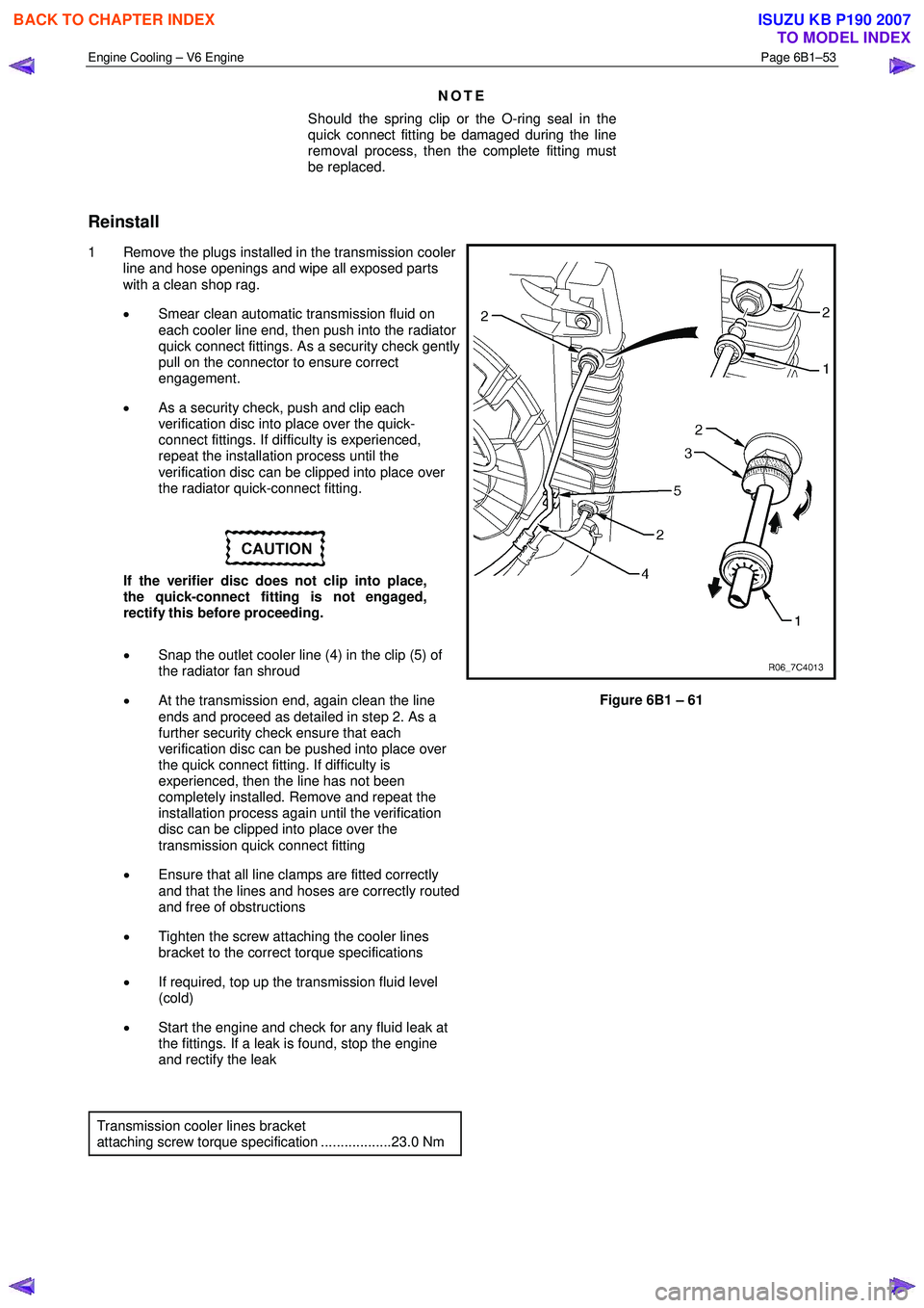
1 Remove the plugs installed in the transmission cooler line and hose openings and wipe all exposed parts
with a clean shop rag.
• Smear clean automatic transmission fluid on
each cooler line end, then push into the radiator
quick connect fittings. As a security check gently
pull on the connector to ensure correct
engagement.
• As a security check, push and clip each
verification disc into place over the quick-
connect fittings. If difficulty is experienced,
repeat the installation process until the
verification disc can be clipped into place over
the radiator quick-connect fitting.
If the verifier disc does not clip into place,
the quick-connect fitting is not engaged,
rectify this before proceeding.
• Snap the outlet cooler line (4) in the clip (5) of
the radiator fan shroud
• At the transmission end, again clean the line
ends and proceed as detailed in step 2. As a
further security check ensure that each
verification disc can be pushed into place over
the quick connect fitting. If difficulty is
experienced, then the line has not been
completely installed. Remove and repeat the
installation process again until the verification
disc can be clipped into place over the
transmission quick connect fitting
• Ensure that all line clamps are fitted correctly
and that the lines and hoses are correctly routed
and free of obstructions
• Tighten the screw attaching the cooler lines
bracket to the correct torque specifications
• If required, top up the transmission fluid level
(cold)
• Start the engine and check for any fluid leak at
the fittings. If a leak is found, stop the engine
and rectify the leak
Figure 6B1 – 61
Transmission cooler lines bracket
attaching screw torque specification ..................23.0 Nm
BACK TO CHAPTER INDEX
TO MODEL INDEX
ISUZU KB P190 2007
Page 3191 of 6020
Engine Cooling – V6 Engine Page 6B1–56
Reinstall
Installation of the radiator is the reverse of removal procedures, noting the following points:
1 Before installing radiator, inspect core to ensure that there is no foreign matter in core fins. Clean out between core fins with compressed air, blowing from rear to front.
2 If the vehicle is fitted with an automatic transmission, remove plugs from the removed cooling pipe ends and the two quick connect fittings.
3 After wiping cooler line ends and smearing clean automatic transmission fluid over each flared line end, push into the quick connect fitting to engage. As a security check, tug on each line to ensure correct engagement.
4 Check the transmission fluid level. Refer to the following references as required:
• 7C4 Automatic Transmission
• 4L60E On-vehicle Servicing
5 Install the following hoses:
a. Lower radiator hose, securing with the hose clamp.
b. Upper radiator hose, securing with the hose clamp.
6 Install the radiator cooling fan and shroud assembly. Refer to 3.13Cooling Fan and Shroud Assembly in this Section. Ensure that electrical connectors and the transmission cooler lines are seated correctly in the integral
retainer clips before install upper radiator shroud.
7 Refill cooling system. Refer to 3.3 Draining and Filling Cooling System in this Section.
8 Check for coolant leaks. Refer to 3.7 Pressure Testing in this Section.
9 Reconnect battery ground lead. Refer to 8A Electrical Body & Chassis.
10 Check cooling fan operation. Refer to 6C1-2 Engine Management Diagnostics. Also check for correct rotational direction of cooling fan.
BACK TO CHAPTER INDEX
TO MODEL INDEX
ISUZU KB P190 2007