warning ISUZU KB P190 2007 Workshop Repair Manual
[x] Cancel search | Manufacturer: ISUZU, Model Year: 2007, Model line: KB P190, Model: ISUZU KB P190 2007Pages: 6020, PDF Size: 70.23 MB
Page 67 of 6020
HEATER AND AIR CONDITIONING 1-33
RECOVERY, RECYCLING, EVACUATION
AND CHARGING
Handling Refrigerant-134a (HFC-134a)
Air conditioning systems contain HFC-134a.
This is a chemical mixture, which requires special handling
procedures to avoid personal injury.
• Always wear safety goggles and protective gloves.
• Always work in a well-ventilated area. Do not weld or steam
clean on or near any vehicle-installed air conditioning lines
or components.
• If HFC-134a should come in contact with any part of the
body, flush the exposed area with cold water and
immediately seek medical help.
• If it is necessary to transport or carry any container of HFC-
134a in a vehicle, do not carry it in the passenger
compartment.
• If it is necessary to fill a small HFC-134a container from a
large one, never fill the container completely. Space should
always be allowed above the liquid for expansion.
• Keep HFC-134a containers stored below 40 °C (104 °F).
WARNING
•
••
•
SHOULD HFC-134a CONTACT YOUR EYE(S), CONSULT
A DOCTOR IMMEDIATELY.
•
••
•
DO NOT RUB THE AFFECTED EYE(S). INSTEAD,
SPLASH QUANTITIES OF FRESH COLD WATER OVER
THE AFFECTED AREA TO GRADUALLY RAISE THE
TEMPERATURE OF THE REFRIGERANT ABOVE THE
FREEZING POINT.
•
••
•
OBTAIN PROPER MEDICAL TREATMENT AS SOON AS
POSSIBLE. SHOULD THE HFC-134a TOUCH THE SKIN,
THE INJURY MUST BE TREATED THE SAME AS SKIN
WHICH HAS BEEN FROSTBITTEN OR FROZEN.
F06R300012
REFRIGERANT RECOVERY
The refrigerant must be discharged and recovered by using
ACR4 (HFC-134a Refrigerant Recovery/Recycling/Recharging/
System) or equivalent before removing or installing air
conditioning parts.
ACR
4 (115V 60Hz) :5-8840-0629-0 (J-39500-A)
ACR4 (220-240V 50/60Hz)
: 5-8840-0630-0 (J-39500-220A)
ACR
4 (220-240V 50/60Hz Australian model)
: 5-8840-0631-0 (J-39500-220ANZ)
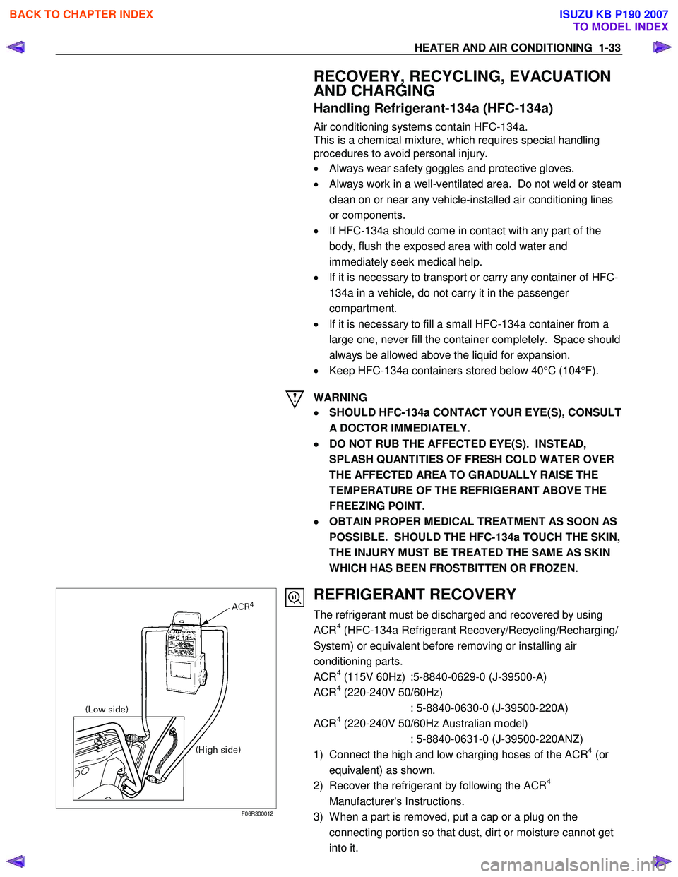
1) Connect the high and low charging hoses of the ACR
4 (or
equivalent) as shown.
2) Recover the refrigerant by following the ACR
4
Manufacturer's Instructions.
3) W hen a part is removed, put a cap or a plug on the connecting portion so that dust, dirt or moisture cannot get
into it.
BACK TO CHAPTER INDEX
TO MODEL INDEX
ISUZU KB P190 2007
Page 71 of 6020
HEATER AND AIR CONDITIONING 1-37
refrigerant container.
1) Make sure the evacuation process is correctly completed.
2) Connect the center-hose of the manifold gauge to the refrigerant container. •
••
•
Turn the charge valve handle counterclockwise to purge
to the charging line and purge any air exiting in the
center-hose of the manifold gauge.
3) Open the low-pressure hand valve and charge the refrigerant about 200 g (0.44 lbs.). •
••
•
Make sure the high-pressure hand valve is closed.
•
••
•
Avoid charging the refrigerant by turning the refrigerant
container upside down.
4) Close the low-pressure hand valve of the manifold gauge. •
••
•
Check to ensure that the degree of pressure does not
change.
5) Check the refrigerant leaks by using a HFC-134a leak detector. •
••
•
If a leak occurs, repair the leak connection, and start all
over again from the first step of evacuation.
6) If no leaks are found, open the low-pressure hand valve of the manifold gauge. Then continue charging refrigerant to
the system. •
••
•
W hen charging the system becomes difficult:
(1) Run the engine at Idling and close the all vehicle doors.
(2) A/C switch is "ON".
(3) Set the fan control knob (fan switch) to its highest position.
(4) Set air source selector lever to “RECIRC”
WARNING
BE ABSOLUTELY SURE NOT TO OPEN THE HIGH-
PRESSURE HAND VALVE. SHOULD THE HIGH-
PRESSURE HAND VALVE BE OPENED, THE HIGH-
PRESSURE REFRIGERANT GAS WOULD FLOW
BACKWARD, AND THIS MAY CAUSE THE REFRIGERANT
CONTAINER TO BURST.
7) W hen the refrigerant container is emptied, use the following procedure to replace it with a new refrigerant container.
(1) Close the low-pressure hand valve.
(2) Raise the needle upward and remove the charge valve.
(3) Reinstall the charge valve to the new refrigerant container.
(4) Purge any air existing in the center hose of the manifold gauge.
BACK TO CHAPTER INDEX
TO MODEL INDEX
ISUZU KB P190 2007
Page 267 of 6020
3B-6 POWER-ASSISTED STEERING SYSTEM
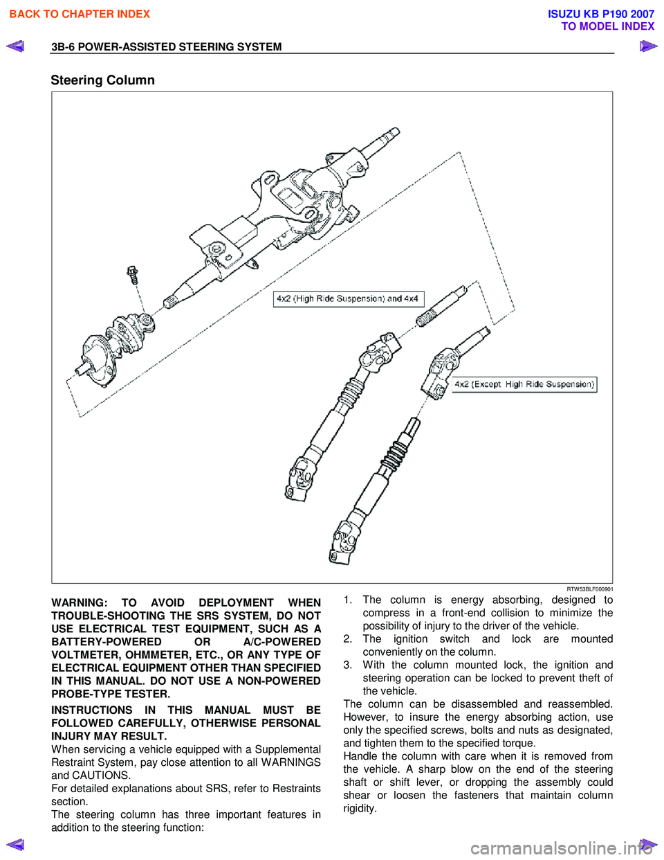
Steering Column
RTW 53BLF000901
WARNING: TO AVOID DEPLOYMENT WHEN
TROUBLE-SHOOTING THE SRS SYSTEM, DO NOT
USE ELECTRICAL TEST EQUIPMENT, SUCH AS
A
BATTERY-POWERED OR A/C-POWERED
VOLTMETER, OHMMETER, ETC., OR ANY TYPE OF
ELECTRICAL EQUIPMENT OTHER THAN SPECIFIED
IN THIS MANUAL. DO NOT USE A NON-POWERED
PROBE-TYPE TESTER.
INSTRUCTIONS IN THIS MANUAL MUST BE
FOLLOWED CAREFULLY, OTHERWISE PERSONAL
INJURY MAY RESULT.
W hen servicing a vehicle equipped with a Supplemental
Restraint System, pay close attention to all W ARNINGS
and CAUTIONS.
For detailed explanations about SRS, refer to Restraints
section.
The steering column has three important features in
addition to the steering function:
1. The column is energy absorbing, designed to
compress in a front-end collision to minimize the
possibility of injury to the driver of the vehicle.
2. The ignition switch and lock are mounted conveniently on the column.
3. W ith the column mounted lock, the ignition and steering operation can be locked to prevent theft o
f
the vehicle.
The column can be disassembled and reassembled.
However, to insure the energy absorbing action, use
only the specified screws, bolts and nuts as designated,
and tighten them to the specified torque.
Handle the column with care when it is removed from
the vehicle. A sharp blow on the end of the steering
shaft or shift lever, or dropping the assembly could
shear or loosen the fasteners that maintain column
rigidity.
BACK TO CHAPTER INDEX
TO MODEL INDEX
ISUZU KB P190 2007
Page 288 of 6020
POWER-ASSISTED STEERING SYSTEM 3B-27
Supplemental Restraint System Steering Wheel & Column
Service Precaution
This steering wheel and column repair section covers
the Supplemental Restraint System (SRS) steering
column. The following repair procedures are specific to
SRS components. W hen servicing a vehicle equipped
with Supplemental Restraint System, pay close attention
to all W ARNINGS and CAUTIONS.
For detailed explanation about SRS, refer to Restraints
section.
WARNING: THIS VEHICLE HAS A SUPPLEMENTAL
RESTRAINT SYSTEM (SRS). REFER TO THE SRS
COMPONENT AND WIRING LOCATION VIEW IN
ORDER TO DETERMINE WHETHER YOU ARE
PERFORMING SERVICE ON OR NEAR THE SRS
COMPONENTS OR THE SRS WIRING. WHEN YOU
ARE PERFORMING SERVICE ON OR NEAR THE
SRS COMPONENTS OR THE SRS WIRING, REFER
TO THE SRS SERVICE INFORMATION. FAILURE TO
FOLLOW WARNINGS COULD RESULT IN POSSIBLE
AIR BAG DEPLOYMENT, PERSONAL INJURY, OR
OTHERWISE UNNECESSARY SRS SYSTEM
REPAIRS.
SAFE HANDLING OF INFLATOR MODULES
REQUIRES THE PROCEDURES DESCRIBED
BELOW TO BE FOLLOWED FOR BOTH LIVE AND
DEPLOYED MODULES.
SAFETY PRECAUTIONS MUST BE FOLLOWED
WHEN HANDLING A DEPLOYED AIR BAG
ASSEMBLY (AIR BAG). AFTER DEPLOYMENT, THE
AIR BAG ASSEMBLY (AIR BAG) SURFACE MAY
CONTAIN A SMALL AMOUNT OF SODIUM
HYDROXIDE, A BY-PRODUCT OF THE
DEPLOYMENT REACTION, THAT IS IRRITATING TO
THE SKIN AND EYES. MOST OF THE POWDER ON
THE AIR BAG ASSEMBLY (AIR BAG) IS HARMLESS.
AS A PRECAUTION, WEAR GLOVES AND SAFETY
GLASSES WHEN HANDLING A DEPLO
YED AIR BAG
ASSEMBLY, AND WASH YOUR HANDS WITH MILD
SOAP AND WATER AFTERWARDS.
WHEN CARRYING A LIVE AIR BAG ASSEMBLY,
MAKE SURE THE BAG AND TRIM COVER ARE
POINTED AWAY FROM YOU. NEVER CARRY AN AIR
BAG ASSEMBLY BY THE WIRES OR CONNECTOR
ON THE UNDERSIDE OF MODULE. IN THE CASE OF
AN ACCIDENTAL DEPLOYMENT, THE BAG WILL
THEN DEPLOY WITH MINIMAL CHANCE OF INJURY.
WHEN PLACING A LIVE AIR BAG ASSEMBLY ON
A
BENCH OR OTHER SURFACE, ALWAYS FACE THE
BAG AND TRIM COVER UP, AWAY FROM THE
SURFACE.
NEVER REST A STEERING COLUMN ASSEMBLY
ON THE STEERING WHEEL WITH THE AIR BAG
ASSEMBLY FACE DOWN AND COLUMN VERTICAL.
THIS IS NECESSARY SO THAT A FREE SPACE IS
PROVIDED TO ALLOW THE AIR BAG ASSEMBLY
TO EXPAND IN THE UNLIKELY EVENT OF
ACCIDENTAL DEPLOYMENT. OTHERWISE,
PERSONAL INJURY COULD RESULT.
TO AVOID DEPLOYMENT WHEN
TROUBLESHOOTING THE SRS SYSTEM, DO NOT
USE ELECTRICAL TEST EQUIPMENT, SUCH AS
A
BATTERY-POWERED OR A/C-POWERED VOLT-
METER, OHMMETER, ETC., OR ANY TYPE OF
ELECTRICAL EQUIPMENT OTHER THAN SPECIFIED
IN THIS MANUAL. DO NOT USE A NON-POWERED
PROBE-TYPE TESTER.
INSTRUCTIONS IN THIS MANUAL MUST BE
FOLLOWED CAREFULLY, OTHERWISE PERSONAL
INJURY MAY RESULT.
SRS Connectors
CAUTION: The special yellow color connectors are
used for the supplemental restraint system-air bag
circuit.
When removing the cable harness, do not pull the
cables. Otherwise, cable disconnection may occur.
When connecting the SRS connector, insert the
connector completely. Imperfect locking may cause
malfunction of the SRS circuit.
BACK TO CHAPTER INDEX
TO MODEL INDEX
ISUZU KB P190 2007
Page 291 of 6020
3B-30 POWER-ASSISTED STEERING SYSTEM
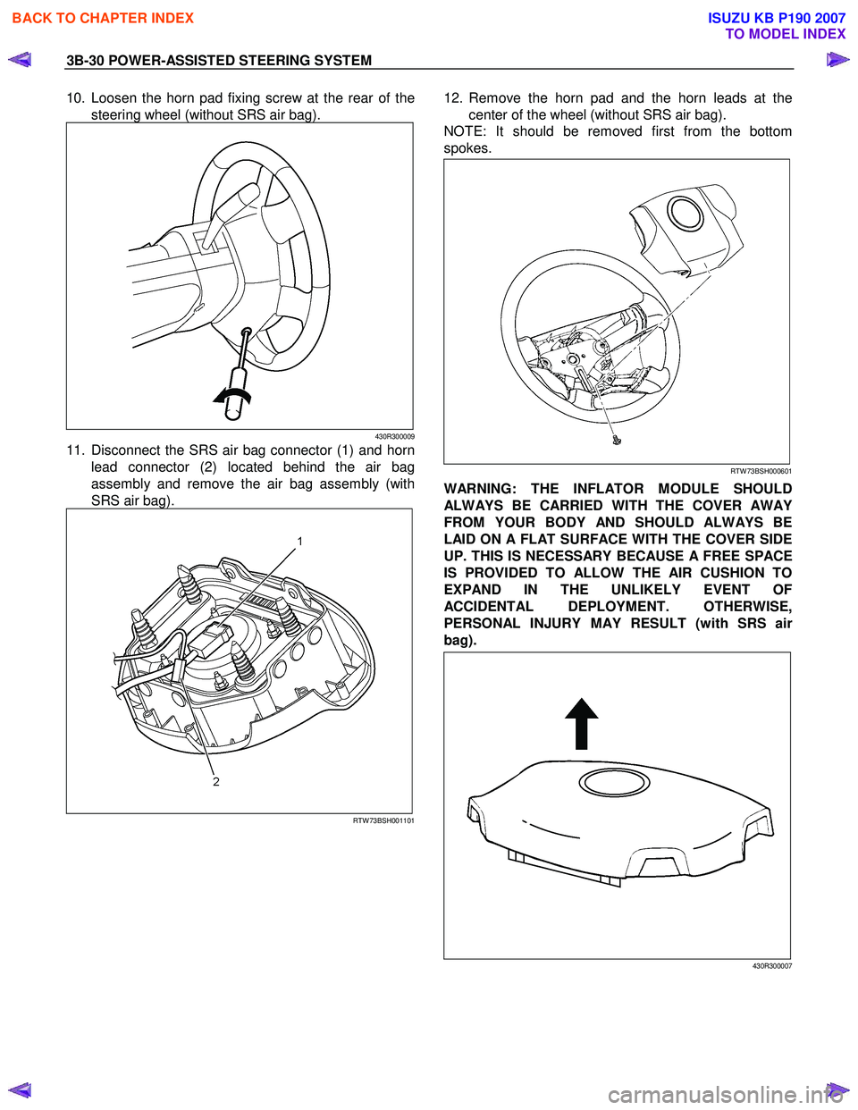
10. Loosen the horn pad fixing screw at the rear of the
steering wheel (without SRS air bag).
430R300009
11. Disconnect the SRS air bag connector (1) and horn lead connector (2) located behind the air bag
assembly and remove the air bag assembly (with
SRS air bag).
RTW 73BSH001101
12. Remove the horn pad and the horn leads at the
center of the wheel (without SRS air bag).
NOTE: It should be removed first from the bottom
spokes.
RTW 73BSH000601
WARNING: THE INFLATOR MODULE SHOULD
ALWAYS BE CARRIED WITH THE COVER AWAY
FROM YOUR BODY AND SHOULD ALWAYS BE
LAID ON A FLAT SURFACE WITH THE COVER SIDE
UP. THIS IS NECESSARY BECAUSE A FREE SPACE
IS PROVIDED TO ALLOW THE AIR CUSHION TO
EXPAND IN THE UNLIKELY EVENT OF
ACCIDENTAL DEPLOYMENT. OTHERWISE,
PERSONAL INJURY MAY RESULT (with SRS ai
r
bag).
430R300007
BACK TO CHAPTER INDEX
TO MODEL INDEX
ISUZU KB P190 2007
Page 293 of 6020
3B-32 POWER-ASSISTED STEERING SYSTEM
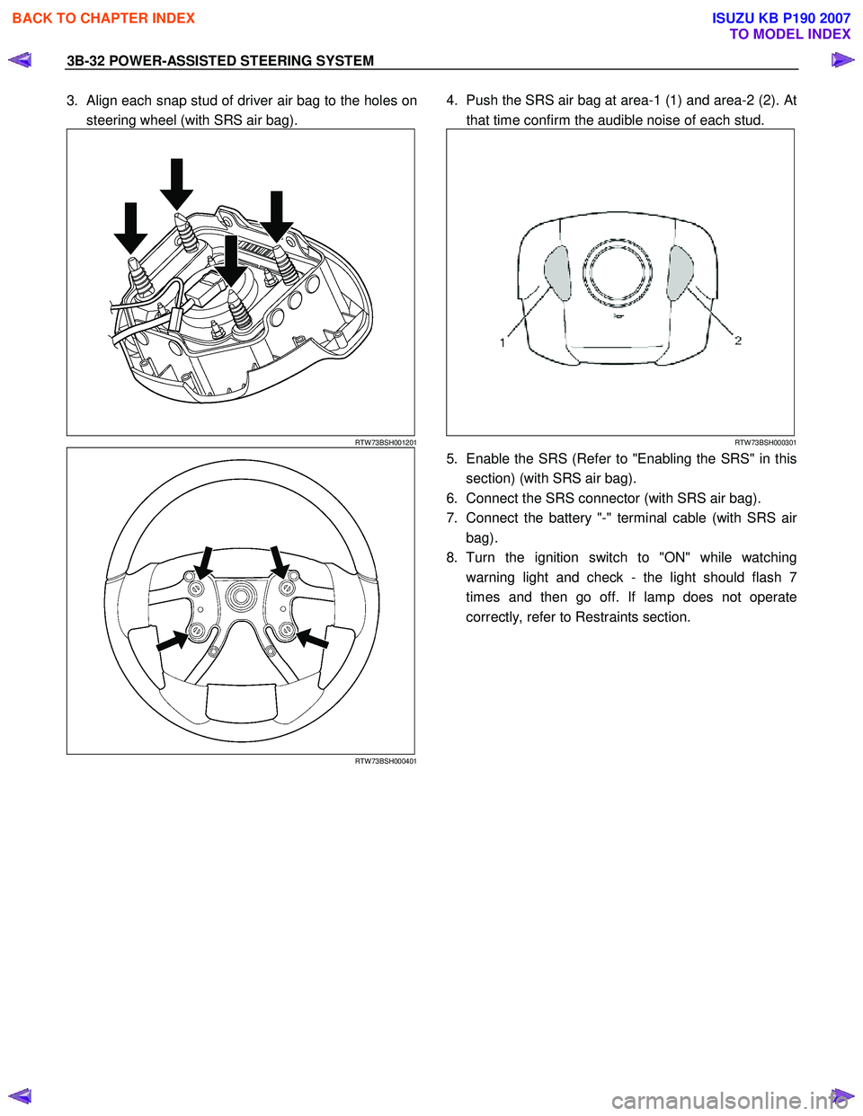
3. Align each snap stud of driver air bag to the holes on
steering wheel (with SRS air bag).
RTW 73BSH001201
RTW 73BSH000401
4. Push the SRS air bag at area-1 (1) and area-2 (2). At
that time confirm the audible noise of each stud.
RTW 73BSH000301
5. Enable the SRS (Refer to "Enabling the SRS" in this
section) (with SRS air bag).
6. Connect the SRS connector (with SRS air bag).
7. Connect the battery "-" terminal cable (with SRS ai
r
bag).
8. Turn the ignition switch to "ON" while watching warning light and check - the light should flash 7
times and then go off. If lamp does not operate
correctly, refer to Restraints section.
BACK TO CHAPTER INDEX
TO MODEL INDEX
ISUZU KB P190 2007
Page 296 of 6020
POWER-ASSISTED STEERING SYSTEM 3B-35
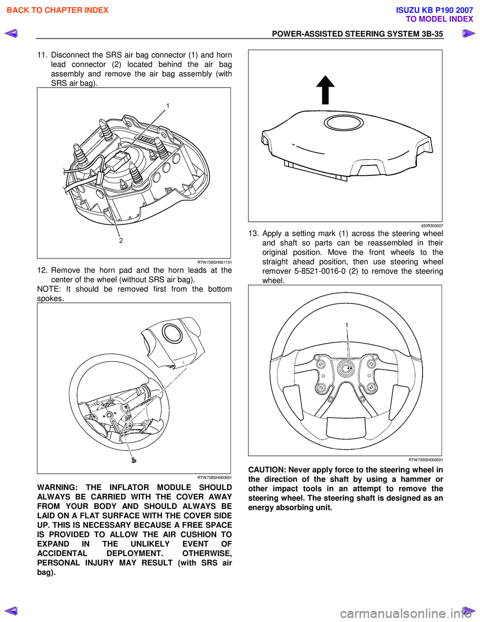
11. Disconnect the SRS air bag connector (1) and horn
lead connector (2) located behind the air bag
assembly and remove the air bag assembly (with
SRS air bag).
RTW 73BSH001101
12. Remove the horn pad and the horn leads at the center of the wheel (without SRS air bag).
NOTE: It should be removed first from the bottom
spokes.
RTW 73BSH000601
WARNING: THE INFLATOR MODULE SHOULD
ALWAYS BE CARRIED WITH THE COVER AWAY
FROM YOUR BODY AND SHOULD ALWAYS BE
LAID ON A FLAT SURFACE WITH THE COVER SIDE
UP. THIS IS NECESSARY BECAUSE A FREE SPACE
IS PROVIDED TO ALLOW THE AIR CUSHION TO
EXPAND IN THE UNLIKELY EVENT OF
ACCIDENTAL DEPLOYMENT. OTHERWISE,
PERSONAL INJURY MAY RESULT (with SRS ai
r
bag).
430R300007
13. Apply a setting mark (1) across the steering wheel
and shaft so parts can be reassembled in thei
r
original position. Move the front wheels to the
straight ahead position, then use steering wheel
remover 5-8521-0016-0 (2) to remove the steering
wheel.
RTW 73BSH000501
CAUTION: Never apply force to the steering wheel in
the direction of the shaft by using a hammer o
r
other impact tools in an attempt to remove the
steering wheel. The steering shaft is designed as an
energy absorbing unit.
BACK TO CHAPTER INDEX
TO MODEL INDEX
ISUZU KB P190 2007
Page 298 of 6020
POWER-ASSISTED STEERING SYSTEM 3B-37
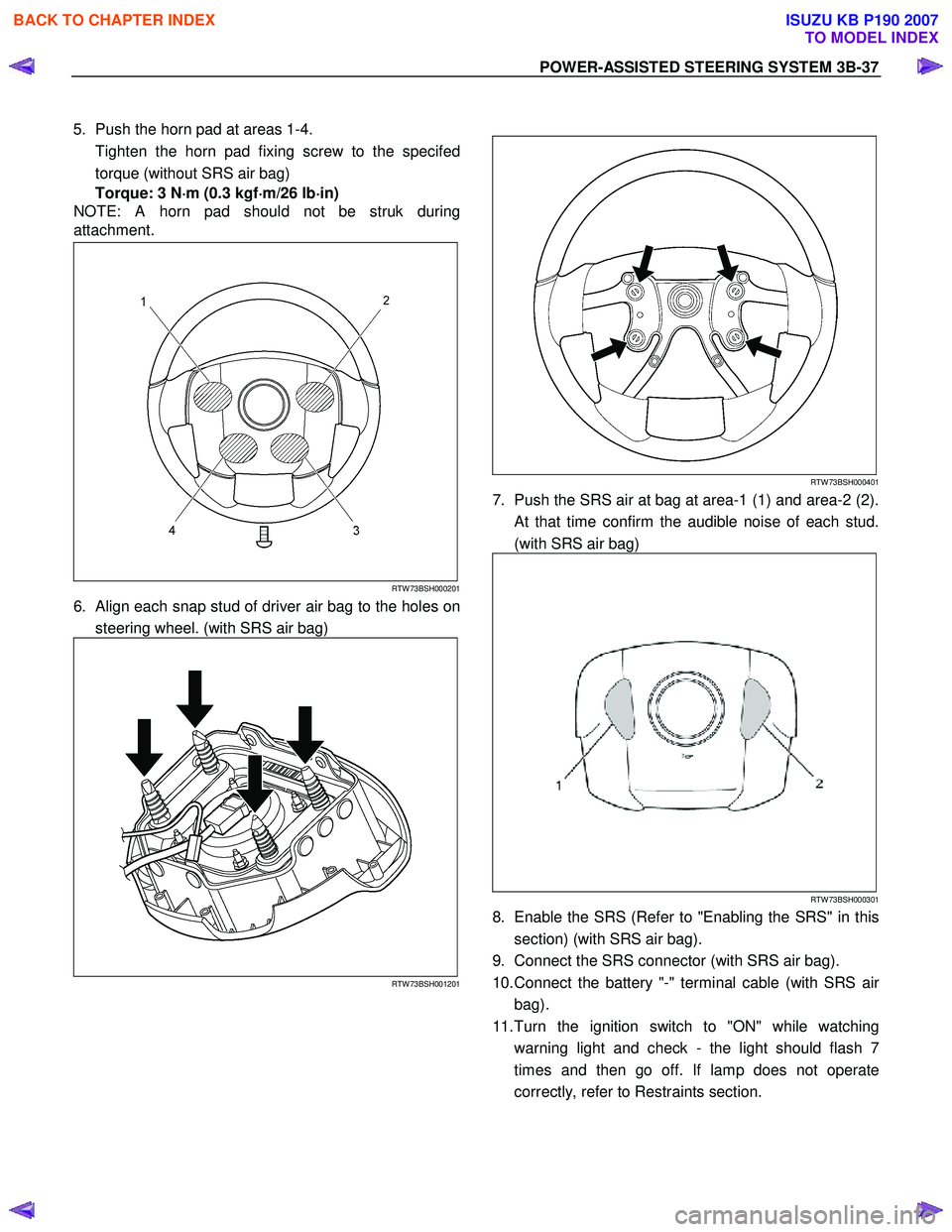
5. Push the horn pad at areas 1-4.
Tighten the horn pad fixing screw to the specifed torque (without SRS air bag)
Torque: 3 N ⋅
⋅⋅
⋅
m (0.3 kgf ⋅
⋅⋅
⋅
m/26 lb ⋅
⋅⋅
⋅
in)
NOTE: A horn pad should not be struk during
attachment.
RTW 73BSH000201
6. Align each snap stud of driver air bag to the holes on
steering wheel. (with SRS air bag)
RTW 73BSH001201
RTW 73BSH000401
7. Push the SRS air at bag at area-1 (1) and area-2 (2).
At that time confirm the audible noise of each stud.
(with SRS air bag)
RTW 73BSH000301
8. Enable the SRS (Refer to "Enabling the SRS" in this section) (with SRS air bag).
9. Connect the SRS connector (with SRS air bag).
10. Connect the battery "-" terminal cable (with SRS ai
r
bag).
11. Turn the ignition switch to "ON" while watching warning light and check - the light should flash 7
times and then go off. If lamp does not operate
correctly, refer to Restraints section.
BACK TO CHAPTER INDEX
TO MODEL INDEX
ISUZU KB P190 2007
Page 302 of 6020
POWER-ASSISTED STEERING SYSTEM 3B-41
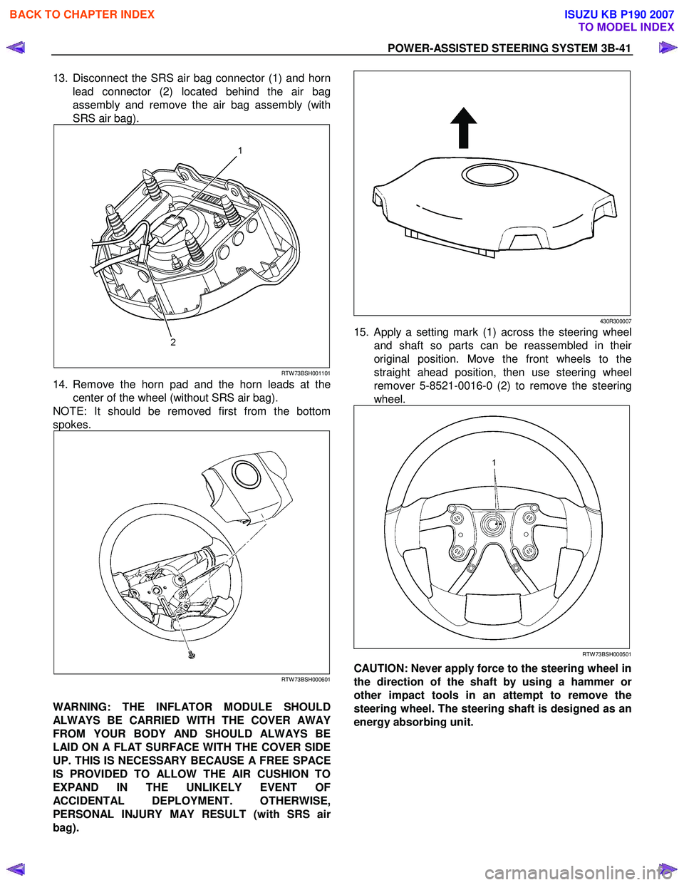
13. Disconnect the SRS air bag connector (1) and horn
lead connector (2) located behind the air bag
assembly and remove the air bag assembly (with
SRS air bag).
RTW 73BSH001101
14. Remove the horn pad and the horn leads at the center of the wheel (without SRS air bag).
NOTE: It should be removed first from the bottom
spokes.
RTW 73BSH000601
WARNING: THE INFLATOR MODULE SHOULD
ALWAYS BE CARRIED WITH THE COVER AWAY
FROM YOUR BODY AND SHOULD ALWAYS BE
LAID ON A FLAT SURFACE WITH THE COVER SIDE
UP. THIS IS NECESSARY BECAUSE A FREE SPACE
IS PROVIDED TO ALLOW THE AIR CUSHION TO
EXPAND IN THE UNLIKELY EVENT OF
ACCIDENTAL DEPLOYMENT. OTHERWISE,
PERSONAL INJURY MAY RESULT (with SRS ai
r
bag).
430R300007
15. Apply a setting mark (1) across the steering wheel
and shaft so parts can be reassembled in thei
r
original position. Move the front wheels to the
straight ahead position, then use steering wheel
remover 5-8521-0016-0 (2) to remove the steering
wheel.
RTW 73BSH000501
CAUTION: Never apply force to the steering wheel in
the direction of the shaft by using a hammer o
r
other impact tools in an attempt to remove the
steering wheel. The steering shaft is designed as an
energy absorbing unit.
BACK TO CHAPTER INDEX
TO MODEL INDEX
ISUZU KB P190 2007
Page 305 of 6020
3B-44 POWER-ASSISTED STEERING SYSTEM
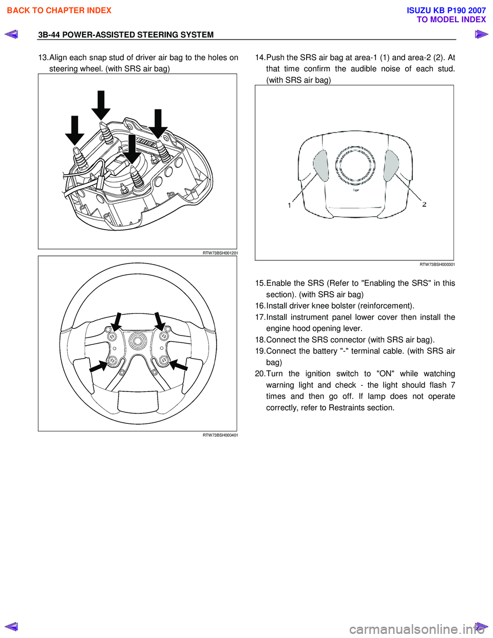
13. Align each snap stud of driver air bag to the holes on
steering wheel. (with SRS air bag)
RTW 73BSH001201
RTW 73BSH000401
14. Push the SRS air bag at area-1 (1) and area-2 (2). At
that time confirm the audible noise of each stud.
(with SRS air bag)
RTW 73BSH000301
15. Enable the SRS (Refer to "Enabling the SRS" in this
section). (with SRS air bag)
16. Install driver knee bolster (reinforcement).
17. Install instrument panel lower cover then install the engine hood opening lever.
18. Connect the SRS connector (with SRS air bag).
19. Connect the battery "-" terminal cable. (with SRS ai
r
bag)
20. Turn the ignition switch to "ON" while watching warning light and check - the light should flash 7
times and then go off. If lamp does not operate
correctly, refer to Restraints section.
BACK TO CHAPTER INDEX
TO MODEL INDEX
ISUZU KB P190 2007