Heat gauge ISUZU KB P190 2007 Workshop Repair Manual
[x] Cancel search | Manufacturer: ISUZU, Model Year: 2007, Model line: KB P190, Model: ISUZU KB P190 2007Pages: 6020, PDF Size: 70.23 MB
Page 68 of 6020
1-34 HEATER AND AIR CONDITIONING
REFRIGERANT RECYCLING
Recycle the refrigerant recovered by ACR4 or equivalent.
For the details of the actual operation, follow the steps in the
ACR
4 Manufacturer's Instructions.
ACR4 (115V 60Hz) :5-8840-0629-0 (J-39500-A)
ACR4 (220-240V 50/60Hz)
: 5-8840-0630-0 (J-39500-220A)
ACR
4 (220-240V 50/60Hz Australian model)
: 5-8840-0631-0 (J-39500-220ANZ)
F06R300014
EVACUATION OF THE REFRIGERANT
SYSTEM
NOTE:
Explained below is a method using a vacuum pump. Refer
to the ACR
4 (or equivalent) Manufacturer's Instructions
when evacuating the system with ACR4 (or equivalent).
Air and moisture in the refrigerant will cause problems in the air
conditioning system.
Therefore, before charging the refrigerant, be sure to evacuate
air and moisture thoroughly from the system.
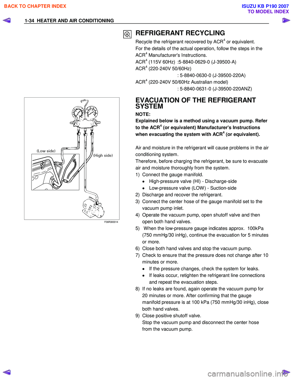
1) Connect the gauge manifold. •
••
•
High-pressure valve (HI) - Discharge-side
•
••
•
Low-pressure valve (LOW ) - Suction-side
2) Discharge and recover the refrigerant.
3) Connect the center hose of the gauge manifold set to the vacuum pump inlet.
4) Operate the vacuum pump, open shutoff valve and then open both hand valves.
5) W hen the low-pressure gauge indicates approx. 100kPa (750 mmHg/30 inHg), continue the evacuation for 5 minutes
or more.
6) Close both hand valves and stop the vacuum pump.
7) Check to ensure that the pressure does not change after 10
minutes or more. •
••
•
If the pressure changes, check the system for leaks.
•
••
•
If leaks occur, retighten the refrigerant line connections
and repeat the evacuation steps.
8) If no leaks are found, again operate the vacuum pump for 20 minutes or more. After confirming that the gauge
manifold pressure is at 100 kPa (750 mmHg/30 inHg), close
both hand valves.
9) Close positive shutoff valve.
Stop the vacuum pump and disconnect the center hose from the vacuum pump.
BACK TO CHAPTER INDEX
TO MODEL INDEX
ISUZU KB P190 2007
Page 69 of 6020
HEATER AND AIR CONDITIONING 1-35
CHARGING THE REFRIGERANT SYSTEM
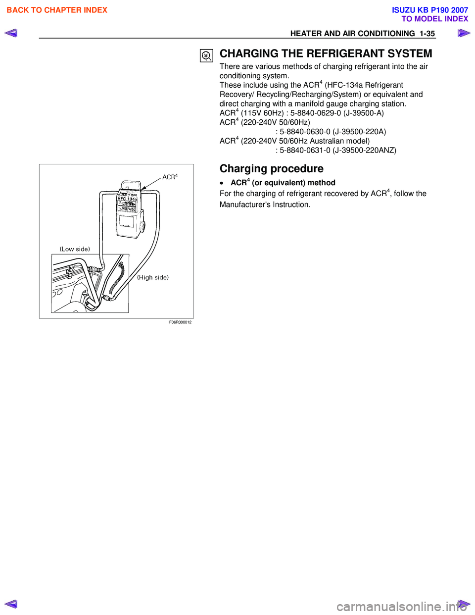
There are various methods of charging refrigerant into the air
conditioning system.
These include using the ACR
4 (HFC-134a Refrigerant
Recovery/ Recycling/Recharging/System) or equivalent and
direct charging with a manifold gauge charging station.
ACR
4 (115V 60Hz) : 5-8840-0629-0 (J-39500-A)
ACR4 (220-240V 50/60Hz)
: 5-8840-0630-0 (J-39500-220A)
ACR
4 (220-240V 50/60Hz Australian model)
: 5-8840-0631-0 (J-39500-220ANZ)
F06R300012
Charging procedure
•
••
•
ACR4 (or equivalent) method
For the charging of refrigerant recovered by ACR4, follow the
Manufacturer's Instruction.
BACK TO CHAPTER INDEX
TO MODEL INDEX
ISUZU KB P190 2007
Page 70 of 6020
1-36 HEATER AND AIR CONDITIONING
F06R300013
•
••
•
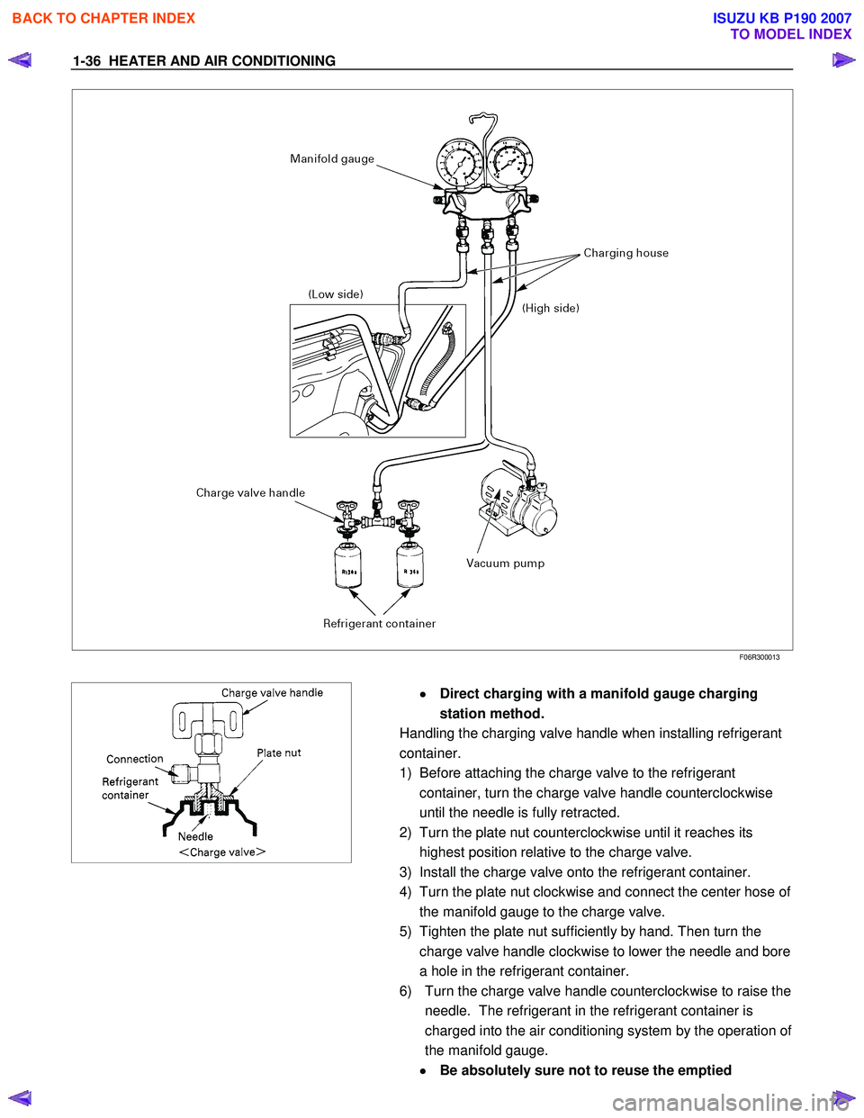
Direct charging with a manifold gauge charging
station method.
Handling the charging valve handle when installing refrigerant
container.
1) Before attaching the charge valve to the refrigerant container, turn the charge valve handle counterclockwise
until the needle is fully retracted.
2) Turn the plate nut counterclockwise until it reaches its highest position relative to the charge valve.
3) Install the charge valve onto the refrigerant container.
4) Turn the plate nut clockwise and connect the center hose of the manifold gauge to the charge valve.
5) Tighten the plate nut sufficiently by hand. Then turn the charge valve handle clockwise to lower the needle and bore
a hole in the refrigerant container.
6) Turn the charge valve handle counterclockwise to raise the needle. The refrigerant in the refrigerant container is
charged into the air conditioning system by the operation of
the manifold gauge.
•
••
•
Be absolutely sure not to reuse the emptied
BACK TO CHAPTER INDEX
TO MODEL INDEX
ISUZU KB P190 2007
Page 71 of 6020
HEATER AND AIR CONDITIONING 1-37
refrigerant container.
1) Make sure the evacuation process is correctly completed.
2) Connect the center-hose of the manifold gauge to the refrigerant container. •
••
•
Turn the charge valve handle counterclockwise to purge
to the charging line and purge any air exiting in the
center-hose of the manifold gauge.
3) Open the low-pressure hand valve and charge the refrigerant about 200 g (0.44 lbs.). •
••
•
Make sure the high-pressure hand valve is closed.
•
••
•
Avoid charging the refrigerant by turning the refrigerant
container upside down.
4) Close the low-pressure hand valve of the manifold gauge. •
••
•
Check to ensure that the degree of pressure does not
change.
5) Check the refrigerant leaks by using a HFC-134a leak detector. •
••
•
If a leak occurs, repair the leak connection, and start all
over again from the first step of evacuation.
6) If no leaks are found, open the low-pressure hand valve of the manifold gauge. Then continue charging refrigerant to
the system. •
••
•
W hen charging the system becomes difficult:
(1) Run the engine at Idling and close the all vehicle doors.
(2) A/C switch is "ON".
(3) Set the fan control knob (fan switch) to its highest position.
(4) Set air source selector lever to “RECIRC”
WARNING
BE ABSOLUTELY SURE NOT TO OPEN THE HIGH-
PRESSURE HAND VALVE. SHOULD THE HIGH-
PRESSURE HAND VALVE BE OPENED, THE HIGH-
PRESSURE REFRIGERANT GAS WOULD FLOW
BACKWARD, AND THIS MAY CAUSE THE REFRIGERANT
CONTAINER TO BURST.
7) W hen the refrigerant container is emptied, use the following procedure to replace it with a new refrigerant container.
(1) Close the low-pressure hand valve.
(2) Raise the needle upward and remove the charge valve.
(3) Reinstall the charge valve to the new refrigerant container.
(4) Purge any air existing in the center hose of the manifold gauge.
BACK TO CHAPTER INDEX
TO MODEL INDEX
ISUZU KB P190 2007
Page 72 of 6020
1-38 HEATER AND AIR CONDITIONING
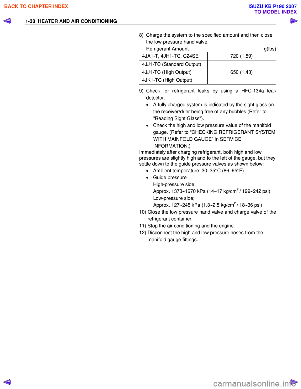
8) Charge the system to the specified amount and then close the low-pressure hand valve.
Refrigerant Amount g(lbs)
4JA1-T, 4JH1-TC, C24SE 720 (1.59)
4JJ1-TC (Standard Output)
4JJ1-TC (High Output)
4JK1-TC (High Output)
650 (1.43)
9) Check for refrigerant leaks by using a HFC-134a leak detector.
• A fully charged system is indicated by the sight glass on
the receiver/drier being free of any bubbles (Refer to
"Reading Sight Glass").
• Check the high and low pressure value of the manifold
gauge. (Refer to “CHECKING REFRIGERANT SYSTEM
W ITH MAINFOLD GAUGE” in SERVICE
INFORMATION.)
Immediately after charging refrigerant, both high and low
pressures are slightly high and to the left of the gauge, but they
settle down to the guide pressure valves as shown below:
• Ambient temperature; 30 ∼35 °C (86 ∼95 °F)
• Guide pressure
High-pressure side;
Approx. 1373 ∼1670 kPa (14 ∼17 kg/cm
2 / 199 ∼242 psi)
Low-pressure side;
Approx. 127 ∼245 kPa (1.3 ∼2.5 kg/cm
2 / 18 ∼36 psi)
10) Close the low pressure hand valve and charge valve of the refrigerant container.
11) Stop the air conditioning and the engine.
12) Disconnect the high and low pressure hoses from the manifold gauge fittings.
BACK TO CHAPTER INDEX
TO MODEL INDEX
ISUZU KB P190 2007
Page 124 of 6020
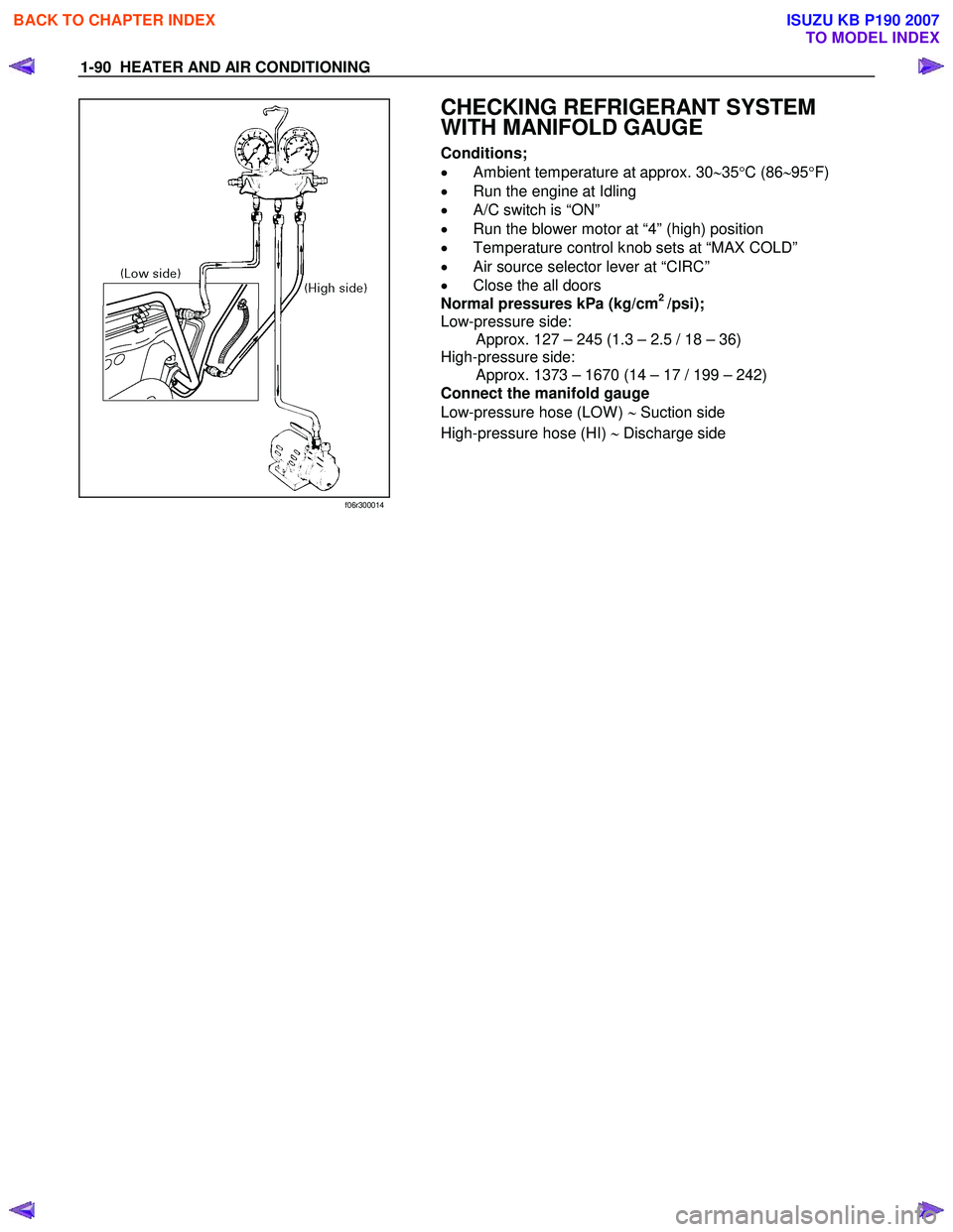
1-90 HEATER AND AIR CONDITIONING
f06r300014
CHECKING REFRIGERANT SYSTEM
WITH MANIFOLD GAUGE
Conditions;
• Ambient temperature at approx. 30 ∼35 °C (86 ∼95 °F)
• Run the engine at Idling
• A/C switch is “ON”
• Run the blower motor at “4” (high) position
• Temperature control knob sets at “MAX COLD”
• Air source selector lever at “CIRC”
• Close the all doors
Normal pressures kPa (kg/cm
2 /psi);
Low-pressure side: Approx. 127 – 245 (1.3 – 2.5 / 18 – 36)
High-pressure side: Approx. 1373 – 1670 (14 – 17 / 199 – 242)
Connect the manifold gauge
Low-pressure hose (LOW ) ∼ Suction side
High-pressure hose (HI) ∼ Discharge side
BACK TO CHAPTER INDEX
TO MODEL INDEX
ISUZU KB P190 2007
Page 125 of 6020
HEATER AND AIR CONDITIONING 1-91
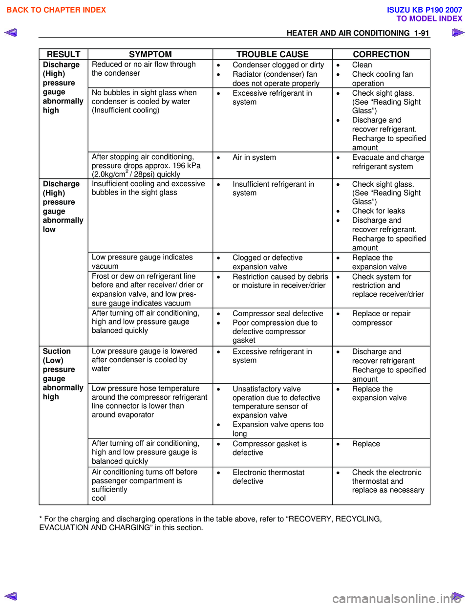
RESULT SYMPTOM TROUBLE CAUSE CORRECTION
Reduced or no air flow through
the condenser
•
Condenser clogged or dirty
• Radiator (condenser) fan
does not operate properly •
Clean
• Check cooling fan
operation
No bubbles in sight glass when
condenser is cooled by water
(Insufficient cooling)
•
Excessive refrigerant in
system
•
Check sight glass.
(See “Reading Sight
Glass”)
• Discharge and
recover refrigerant.
Recharge to specified
amount
Discharge
(High)
pressure
gauge
abnormally
high
After stopping air conditioning,
pressure drops approx. 196 kPa
(2.0kg/cm
2 / 28psi) quickly •
Air in system
•
Evacuate and charge
refrigerant system
Insufficient cooling and excessive
bubbles in the sight glass
•
Insufficient refrigerant in
system
•
Check sight glass.
(See “Reading Sight
Glass”)
• Check for leaks
• Discharge and
recover refrigerant.
Recharge to specified
amount
Low pressure gauge indicates
vacuum •
Clogged or defective
expansion valve •
Replace the
expansion valve
Frost or dew on refrigerant line
before and after receiver/ drier or
expansion valve, and low pres-
sure gauge indicates vacuum •
Restriction caused by debris
or moisture in receiver/drier
•
Check system for
restriction and
replace receiver/drier
Discharge
(High)
pressure
gauge
abnormally
low
After turning off air conditioning,
high and low pressure gauge
balanced quickly
•
Compressor seal defective
• Poor compression due to
defective compressor
gasket •
Replace or repair
compressor
Low pressure gauge is lowered
after condenser is cooled by
water
•
Excessive refrigerant in
system
•
Discharge and
recover refrigerant
Recharge to specified
amount
Low pressure hose temperature
around the compressor refrigerant
line connector is lower than
around evaporator
•
Unsatisfactory valve
operation due to defective
temperature sensor of
expansion valve
• Expansion valve opens too
long •
Replace the
expansion valve
After turning off air conditioning,
high and low pressure gauge is
balanced quickly •
Compressor gasket is
defective
•
Replace
Suction
(Low)
pressure
gauge
abnormally
high
Air conditioning turns off before
passenger compartment is
sufficiently
cool •
Electronic thermostat
defective
•
Check the electronic
thermostat and
replace as necessary
* For the charging and discharging operations in the table above, refer to “RECOVERY, RECYCLING,
EVACUATION AND CHARGING” in this section.
BACK TO CHAPTER INDEX
TO MODEL INDEX
ISUZU KB P190 2007
Page 126 of 6020
1-92 HEATER AND AIR CONDITIONING
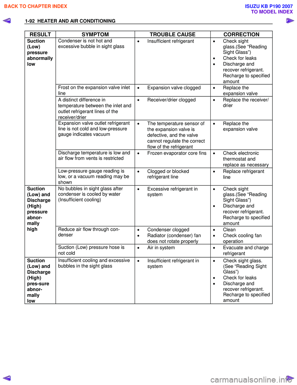
RESULT SYMPTOM TROUBLE CAUSE CORRECTION
Condenser is not hot and
excessive bubble in sight glass
•
Insufficient refrigerant
•
Check sight
glass.(See “Reading
Sight Glass”)
• Check for leaks
• Discharge and
recover refrigerant.
Recharge to specified
amount
Frost on the expansion valve inlet
line •
Expansion valve clogged
•
Replace the
expansion valve
A distinct difference in
temperature between the inlet and
outlet refrigerant lines of the
receiver/drier •
Receiver/drier clogged
•
Replace the receiver/
drier
Expansion valve outlet refrigerant
line is not cold and low-pressure
gauge indicates vacuum
•
The temperature sensor of
the expansion valve is
defective, and the valve
cannot regulate the correct
flow of the refrigerant •
Replace the
expansion valve
Discharge temperature is low and
air flow from vents is restricted
•
Frozen evaporator core fins
•
Check electronic
thermostat and
replace as necessary
Suction
(Low)
pressure
abnormally
low
Low-pressure gauge reading is
low, or a vacuum reading may be
shown •
Clogged or blocked
refrigerant line
•
Replace refrigerant
line
No bubbles in sight glass after
condenser is cooled by water
(Insufficient cooling)
•
Excessive refrigerant in
system
•
Check sight
glass.(See “Reading
Sight Glass”)
• Discharge and
recover refrigerant.
Recharge to specified
amount
Reduce air flow through con-
denser
•
Condenser clogged
• Radiator (condenser) fan
does not rotate properly •
Clean
• Check cooling fan
operation
Suction
(Low) and
Discharge
(High)
pressure
abnor-
mally
high
Suction (Low) pressure hose is
not cold •
Air in system • Evacuate and charge
refrigerant
Suction
(Low) and
Discharge
(High)
pres-sure
abnor-
mally
low Insufficient cooling and excessive
bubbles in the sight glass •
Insufficient refrigerant in
system
•
Check sight glass.
(See “Reading Sight
Glass”)
• Check for leaks
• Discharge and
recover refrigerant.
Recharge to specified
amount
BACK TO CHAPTER INDEX
TO MODEL INDEX
ISUZU KB P190 2007
Page 585 of 6020
SHIFT ON THE FLY SYSTEM 4C2-7
412RS026
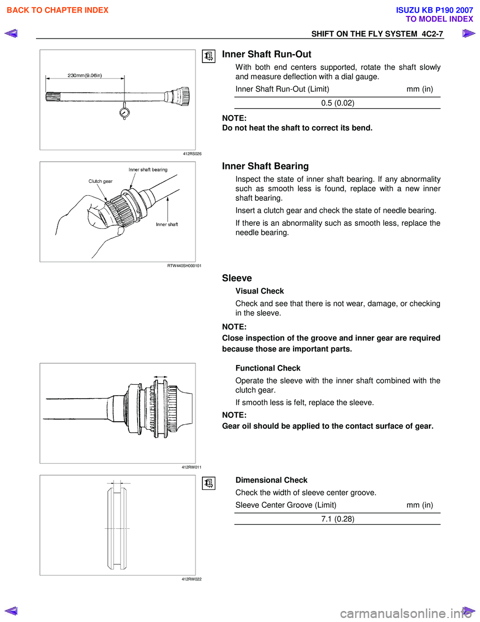
Inner Shaft Run-Out
W ith both end centers supported, rotate the shaft slowly
and measure deflection with a dial gauge.
Inner Shaft Run-Out (Limit) mm (in)
0.5 (0.02)
NOTE:
Do not heat the shaft to correct its bend.
RTW 440SH000101
Inner Shaft Bearing
Inspect the state of inner shaft bearing. If any abnormality
such as smooth less is found, replace with a new inner
shaft bearing.
Insert a clutch gear and check the state of needle bearing.
If there is an abnormality such as smooth less, replace the
needle bearing.
Sleeve
Visual Check
Check and see that there is not wear, damage, or checking
in the sleeve.
NOTE:
Close inspection of the groove and inner gear are required
because those are important parts.
412RW 011
Functional Check
Operate the sleeve with the inner shaft combined with the
clutch gear.
If smooth less is felt, replace the sleeve.
NOTE:
Gear oil should be applied to the contact surface of gear.
412RW 022
Dimensional Check
Check the width of sleeve center groove.
Sleeve Center Groove (Limit) mm (in)
7.1 (0.28)
BACK TO CHAPTER INDEX
TO MODEL INDEX
ISUZU KB P190 2007
Page 848 of 6020
ENGINE MECHANICAL 6A – 43
ENGINE OVERHAUL
REMOVAL
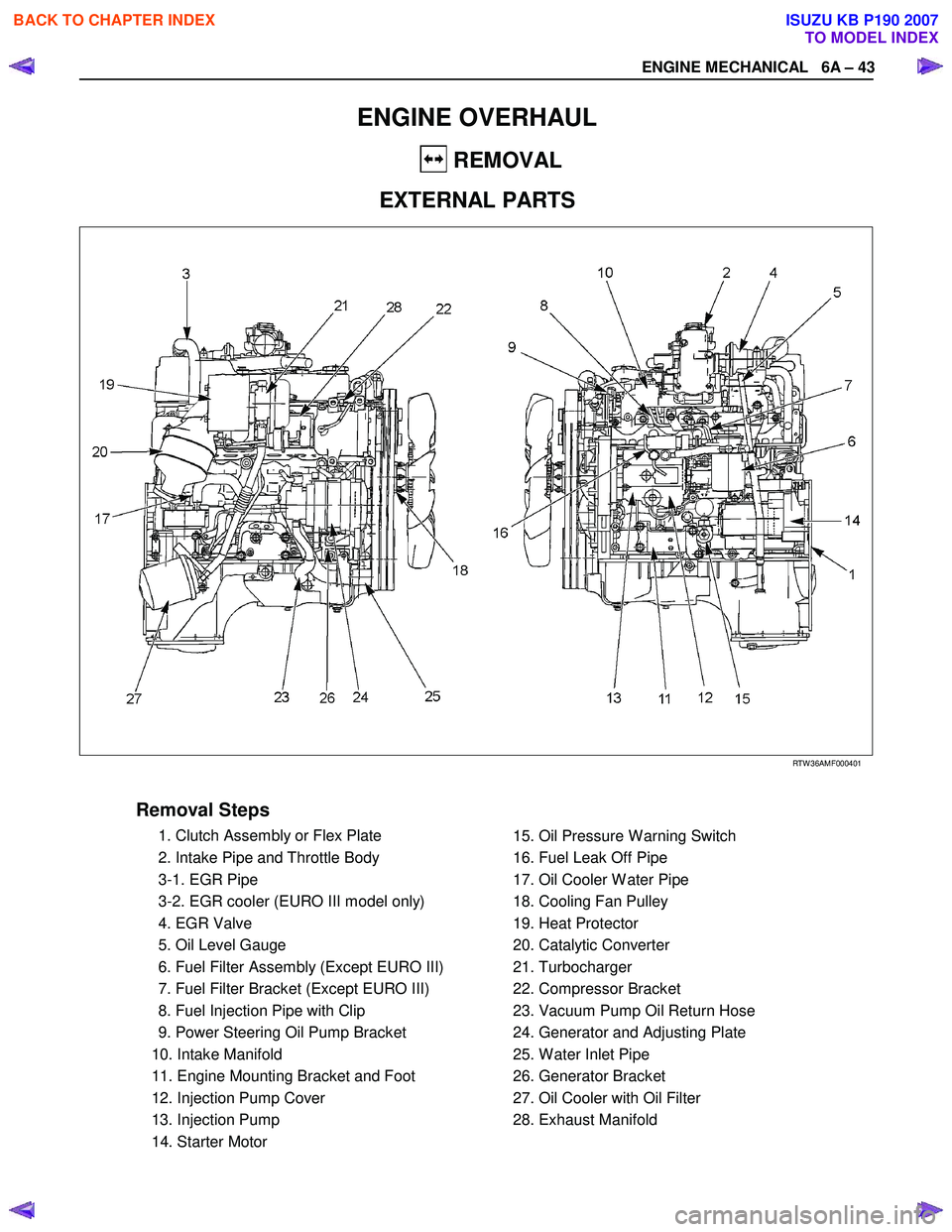
EXTERNAL PARTS
RTW 36AMF000401
Removal Steps
1. Clutch Assembly or Flex Plate
2. Intake Pipe and Throttle Body
3-1. EGR Pipe
3-2. EGR cooler (EURO III model only)
4. EGR Valve
5. Oil Level Gauge
6. Fuel Filter Assembly (Except EURO III)
7. Fuel Filter Bracket (Except EURO III)
8. Fuel Injection Pipe with Clip
9. Power Steering Oil Pump Bracket
10. Intake Manifold
11. Engine Mounting Bracket and Foot
12. Injection Pump Cover
13. Injection Pump
14. Starter Motor
15. Oil Pressure W arning Switch
16. Fuel Leak Off Pipe
17. Oil Cooler W ater Pipe
18. Cooling Fan Pulley
19. Heat Protector
20. Catalytic Converter
21. Turbocharger
22. Compressor Bracket
23. Vacuum Pump Oil Return Hose
24. Generator and Adjusting Plate
25. W ater Inlet Pipe
26. Generator Bracket
27. Oil Cooler with Oil Filter
28. Exhaust Manifold
BACK TO CHAPTER INDEX
TO MODEL INDEX
ISUZU KB P190 2007