headlamp ISUZU KB P190 2007 Workshop Repair Manual
[x] Cancel search | Manufacturer: ISUZU, Model Year: 2007, Model line: KB P190, Model: ISUZU KB P190 2007Pages: 6020, PDF Size: 70.23 MB
Page 3600 of 6020

Charging System – V6 Page 6D1-1-13
20 Reduce the engine speed to idle.
On completion of the generator output test,
return the engine to idle and disconnect the
loading device from the battery terminals.
This prevents excessive battery discharge.
21 Stop the engine.
22 Disconnect the battery ground cable P-5 at the battery.
23 Remove the multimeters.
24 Reconnect the generator positive lead P-9.
25 Reconnect the battery ground cable P-5 to the battery.
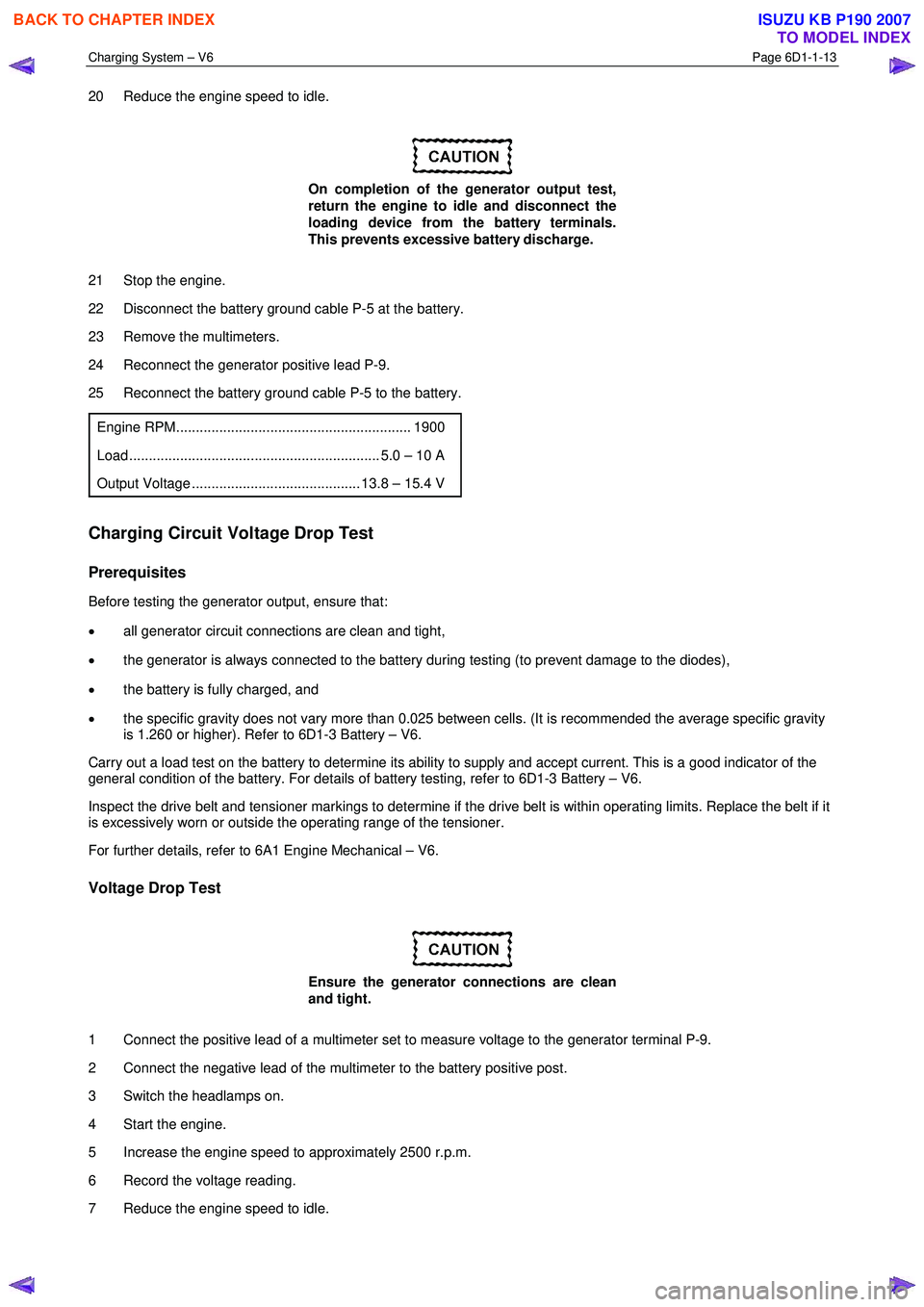
Engine RPM............................................................ 1900
Load ................................................................ 5.0 – 10 A
Output Voltage ........................................... 13.8 – 15.4 V
Charging Circuit Voltage Drop Test
Prerequisites
Before testing the generator output, ensure that:
• all generator circuit connections are clean and tight,
• the generator is always connected to the battery during testing (to prevent damage to the diodes),
• the battery is fully charged, and
• the specific gravity does not vary more than 0.025 between cells. (It is recommended the average specific gravity
is 1.260 or higher). Refer to 6D1-3 Battery – V6.
Carry out a load test on the battery to determine its ability to supply and accept current. This is a good indicator of the
general condition of the battery. For details of battery testing, refer to 6D1-3 Battery – V6.
Inspect the drive belt and tensioner markings to determine if the drive belt is within operating limits. Replace the belt if it
is excessively worn or outside the operating range of the tensioner.
For further details, refer to 6A1 Engine Mechanical – V6.
Voltage Drop Test
Ensure the generator connections are clean
and tight.
1 Connect the positive lead of a multimeter set to measure voltage to the generator terminal P-9.
2 Connect the negative lead of the multimeter to the battery positive post.
3 Switch the headlamps on.
4 Start the engine.
5 Increase the engine speed to approximately 2500 r.p.m.
6 Record the voltage reading.
7 Reduce the engine speed to idle.
BACK TO CHAPTER INDEX
TO MODEL INDEX
ISUZU KB P190 2007
Page 3619 of 6020

Starting System – V6 Page 6D1-2–11
Step Action Yes No
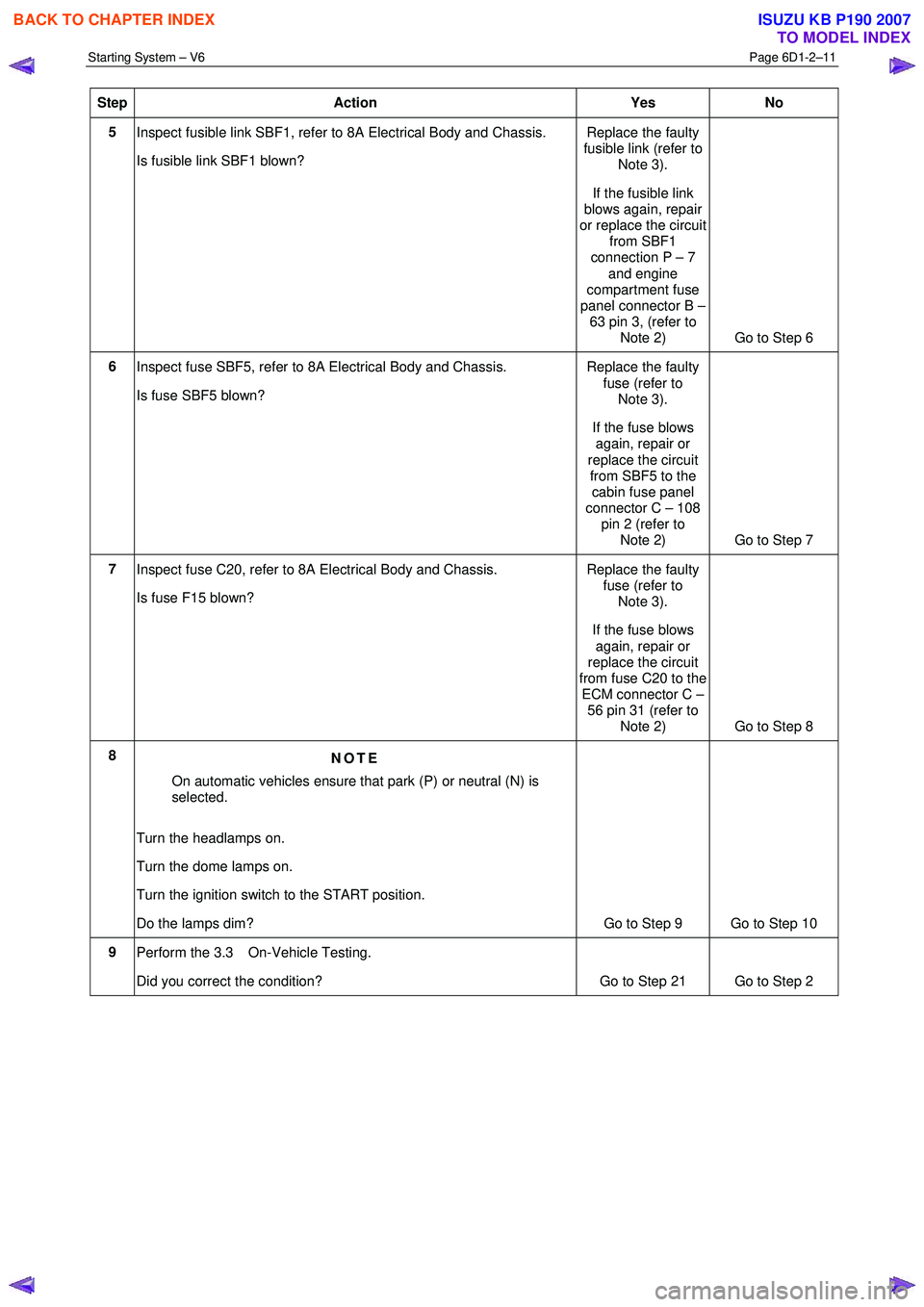
5
Inspect fusible link SBF1, refer to 8A Electrical Body and Chassis.
Is fusible link SBF1 blown? Replace the faulty
fusible link (refer to Note 3).
If the fusible link
blows again, repair
or replace the circuit from SBF1
connection P – 7
and engine
compartment fuse
panel connector B – 63 pin 3, (refer to
Note 2) Go to Step 6
6 Inspect fuse SBF5, refer to 8A Electrical Body and Chassis.
Is fuse SBF5 blown? Replace the faulty
fuse (refer to Note 3).
If the fuse blows again, repair or
replace the circuit from SBF5 to the cabin fuse panel
connector C – 108
pin 2 (refer to Note 2) Go to Step 7
7
Inspect fuse C20, refer to 8A Electrical Body and Chassis.
Is fuse F15 blown? Replace the faulty
fuse (refer to Note 3).
If the fuse blows again, repair or
replace the circuit
from fuse C20 to the ECM connector C –
56 pin 31 (refer to Note 2) Go to Step 8
8 NOTE
On automatic vehicles ensure that park (P) or neutral (N) is
selected.
Turn the headlamps on.
Turn the dome lamps on.
Turn the ignition switch to the START position.
Do the lamps dim? Go to Step 9 Go to Step 10
9
Perform the 3.3 On-Vehicle Testing.
Did you correct the condition?
Go to Step 21 Go to Step 2
BACK TO CHAPTER INDEX
TO MODEL INDEX
ISUZU KB P190 2007
Page 3823 of 6020

Automatic Transmission – 4L60E – Electrical Diagnosis Page 7C2–37
Step Action Yes No
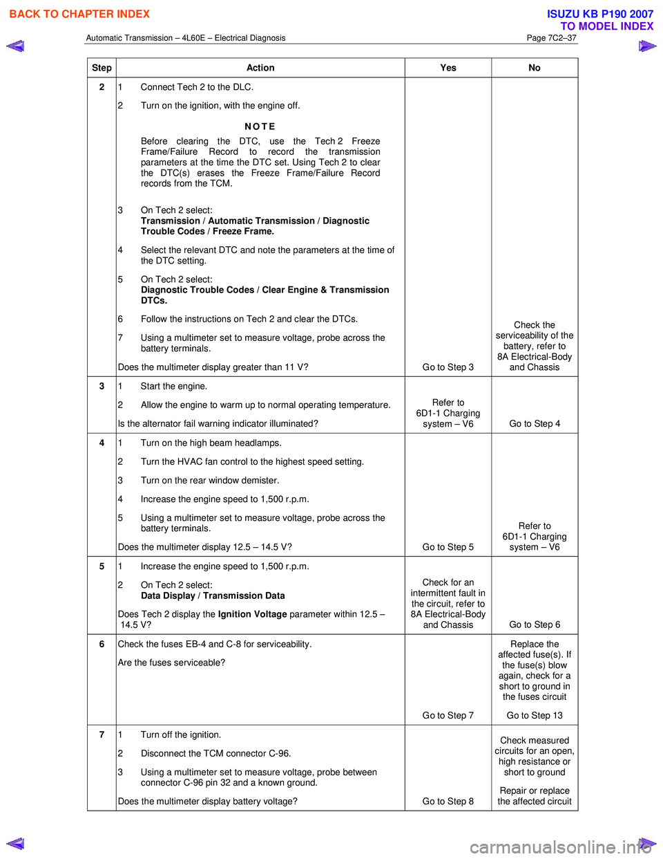
2 1 Connect Tech 2 to the DLC.
2 Turn on the ignition, with the engine off.
NOTE
Before clearing the DTC, use the Tech 2 Freeze
Frame/Failure Record to record the transmission
parameters at the time the DTC set. Using Tech 2 to clear
the DTC(s) erases the Freeze Frame/Failure Record
records from the TCM.
3 On Tech 2 select: Transmission / Automatic Transmission / Diagnostic
Trouble Codes / Freeze Frame.
4 Select the relevant DTC and note the parameters at the time of the DTC setting.
5 On Tech 2 select:
Diagnostic Trouble Codes / Clear Engine & Transmission
DTCs.
6 Follow the instructions on Tech 2 and clear the DTCs.
7 Using a multimeter set to measure voltage, probe across the battery terminals.
Does the multimeter display greater than 11 V? Go to Step 3 Check the
serviceability of the battery, refer to
8A Electrical-Body and Chassis
3 1 Start the engine.
2 Allow the engine to warm up to normal operating temperature.
Is the alternator fail warning indicator illuminated? Refer to
6D1-1 Charging system – V6 Go to Step 4
4 1 Turn on the high beam headlamps.
2 Turn the HVAC fan control to the highest speed setting.
3 Turn on the rear window demister.
4 Increase the engine speed to 1,500 r.p.m.
5 Using a multimeter set to measure voltage, probe across the battery terminals.
Does the multimeter display 12.5 – 14.5 V? Go to Step 5 Refer to
6D1-1 Charging system – V6
5 1 Increase the engine speed to 1,500 r.p.m.
2 On Tech 2 select: Data Display / Transmission Data
Does Tech 2 display the Ignition Voltage parameter within 12.5 –
14.5 V? Check for an
intermittent fault in the circuit, refer to
8A Electrical-Body
and Chassis Go to Step 6
6
Check the fuses EB-4 and C-8 for serviceability.
Are the fuses serviceable?
Go to Step 7 Replace the
affected fuse(s). If the fuse(s) blow
again, check for a short to ground in the fuses circuit
Go to Step 13
7 1 Turn off the ignition.
2 Disconnect the TCM connector C-96.
3 Using a multimeter set to measure voltage, probe between connector C-96 pin 32 and a known ground.
Does the multimeter display battery voltage? Go to Step 8 Check measured
circuits for an open,
high resistance or short to ground
Repair or replace
the affected circuit
BACK TO CHAPTER INDEX
TO MODEL INDEX
ISUZU KB P190 2007