ECU ISUZU KB P190 2007 Workshop Repair Manual
[x] Cancel search | Manufacturer: ISUZU, Model Year: 2007, Model line: KB P190, Model: ISUZU KB P190 2007Pages: 6020, PDF Size: 70.23 MB
Page 1 of 6020
1
WORKSHOP
REPAIR MANUAL
GE NERAL INFORMATION 0
HEATING AND VENTILATION
BRAKESMAIN INDEX ISUZU
CONTENTS
WHEELS AND TYRES
4
5
BODY 8
SECURITY 11 SUSPENSION
3
STEERING
2
AXLE
FRAME AND CAB
ENGINE
6
TRANSMISSION 7
MY 2007
RESTRAINTS 9
CAB 10
BACK TO FRONT PAGE
KB P190
ISUZU KB P190 2007
Page 65 of 6020
HEATER AND AIR CONDITIONING 1-31
REPAIR OF REFRIGERANT LEAKS
Refrigerant Line Connections
RTW 410SH000101
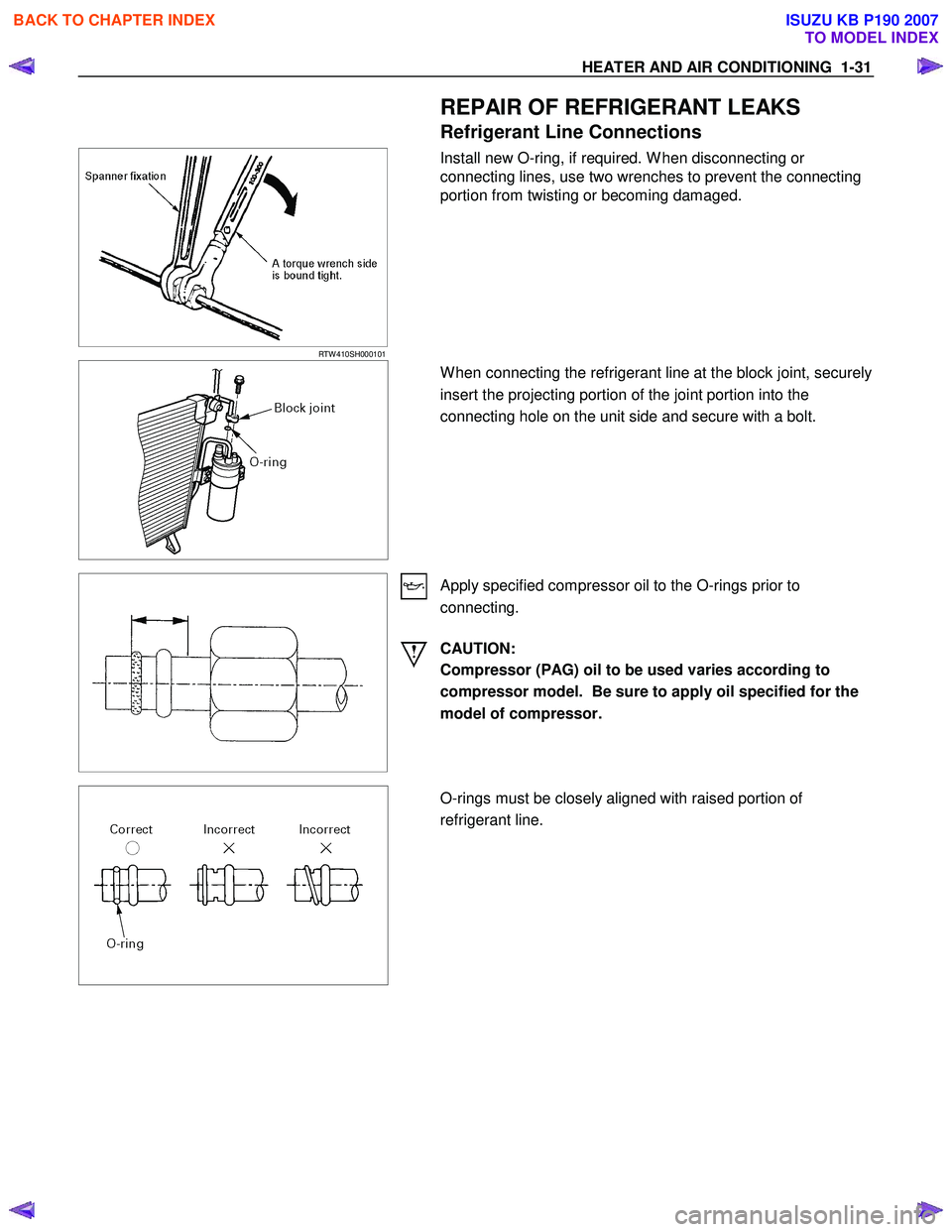
Install new O-ring, if required. W hen disconnecting or
connecting lines, use two wrenches to prevent the connecting
portion from twisting or becoming damaged.
W hen connecting the refrigerant line at the block joint, securely
insert the projecting portion of the joint portion into the
connecting hole on the unit side and secure with a bolt.
Apply specified compressor oil to the O-rings prior to
connecting.
CAUTION:
Compressor (PAG) oil to be used varies according to
compressor model. Be sure to apply oil specified for the
model of compressor.
O-rings must be closely aligned with raised portion of
refrigerant line.
BACK TO CHAPTER INDEX
TO MODEL INDEX
ISUZU KB P190 2007
Page 123 of 6020
HEATER AND AIR CONDITIONING 1-89
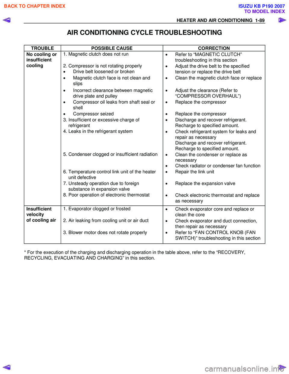
AIR CONDITIONING CYCLE TROUBLESHOOTING
TROUBLE POSSIBLE CAUSE CORRECTION
1. Magnetic clutch does not run
•
Refer to “MAGNETIC CLUTCH”
troubleshooting in this section
2. Compressor is not rotating properly
• Drive belt loosened or broken •
Adjust the drive belt to the specified
tension or replace the drive belt
• Magnetic clutch face is not clean and
slips •
Clean the magnetic clutch face or replace
• Incorrect clearance between magnetic
drive plate and pulley •
Adjust the clearance (Refer to
“COMPRESSOR OVERHAUL”)
• Compressor oil leaks from shaft seal or
shell •
Replace the compressor
• Compressor seized • Replace the compressor
3. Insufficient or excessive charge of
refrigerant •
Discharge and recover refrigerant.
Recharge to specified amount.
4. Leaks in the refrigerant system
•
Check refrigerant system for leaks and
repair as necessary
Discharge and recover refrigerant.
Recharge to specified amount.
5. Condenser clogged or insufficient radiation
•
Clean the condenser or replace as
necessary
• Check radiator or condenser fan function
6. Temperature control link unit of the heater
unit defective •
Repair the link unit
7. Unsteady operation due to foreign
substance in expansion valve •
Replace the expansion valve
No cooling or
insufficient
cooling
8. Poor operation of electronic thermostat
•
Check electronic thermostat and replace
as necessary
1. Evaporator clogged or frosted
•
Check evaporator core and replace or
clean the core
2. Air leaking from cooling unit or air duct
•
Check evaporator and duct connection,
then repair as necessary
Insufficient
velocity
of cooling air
3. Blower motor does not rotate properly
• Refer to “FAN CONTROL KNOB (FAN
SW ITCH)” troubleshooting in this section
* For the execution of the charging and discharging operation in the table above, refer to the “RECOVERY,
RECYCLING, EVACUATING AND CHARGING” in this section.
BACK TO CHAPTER INDEX
TO MODEL INDEX
ISUZU KB P190 2007
Page 209 of 6020
2B-12 SHEET METAL
Important Operations - Installation
4. Control Cable
Reroute the control cable to its original position, and check to
see if the lock assembly and control lever work normally.
2. Engine Hood Lock Assembly
Adjustment
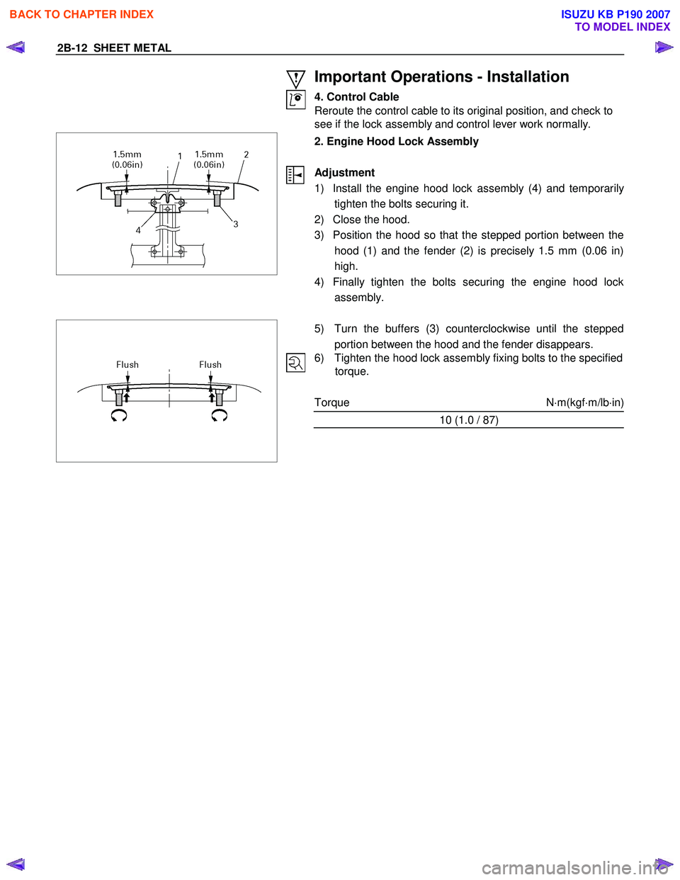
1) Install the engine hood lock assembly (4) and temporaril
y
tighten the bolts securing it.
2) Close the hood.
3) Position the hood so that the stepped portion between the hood (1) and the fender (2) is precisely 1.5 mm (0.06 in)
high.
4) Finally tighten the bolts securing the engine hood lock assembly.
5) Turn the buffers (3) counterclockwise until the stepped
portion between the hood and the fender disappears.
6) Tighten the hood lock assembly fixing bolts to the specified torque.
Torque N ⋅m(kgf ⋅m/lb ⋅in)
10 (1.0 / 87)
BACK TO CHAPTER INDEX
TO MODEL INDEX
ISUZU KB P190 2007
Page 211 of 6020
2B-14 SHEET METAL
Important Operations - Installation
5. Control Cable
Reroute the control cable to its original position, and check to
see if the lock assembly and control lever work normally.
3. Engine Hood Lock Assembly
Adjustment
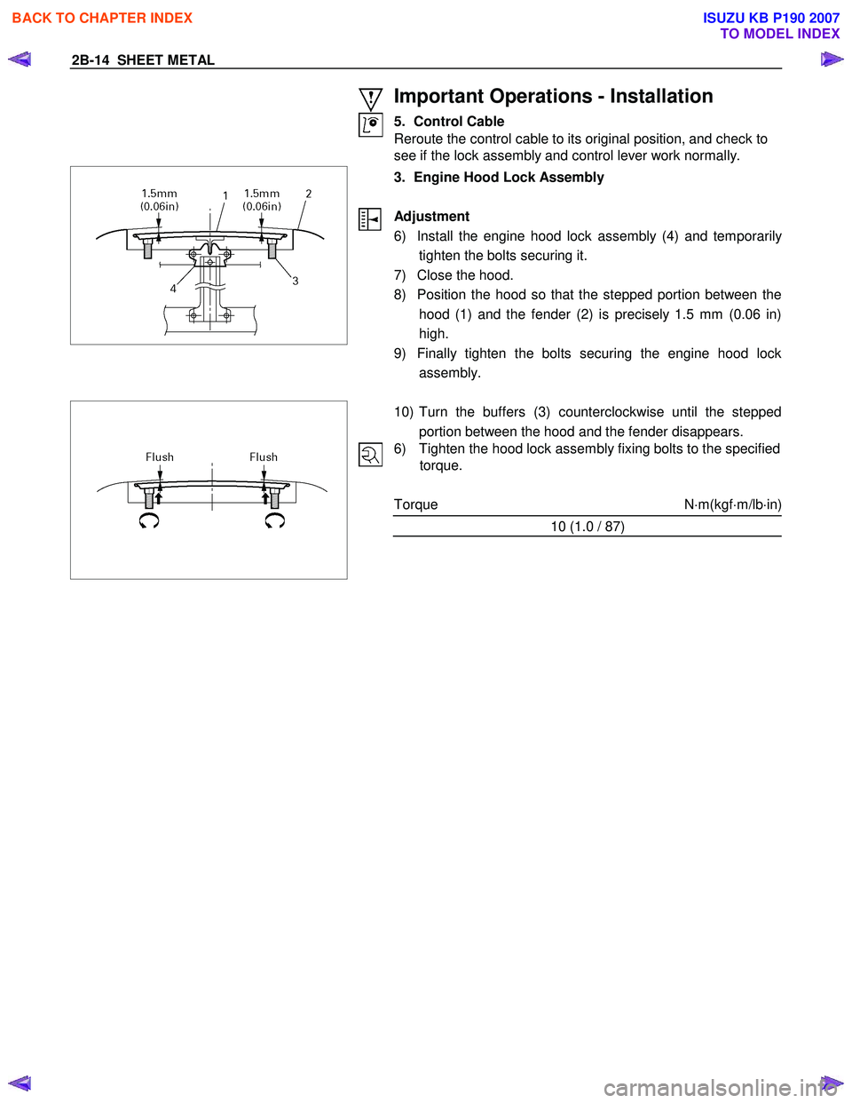
6) Install the engine hood lock assembly (4) and temporaril
y
tighten the bolts securing it.
7) Close the hood.
8) Position the hood so that the stepped portion between the hood (1) and the fender (2) is precisely 1.5 mm (0.06 in)
high.
9) Finally tighten the bolts securing the engine hood lock assembly.
10) Turn the buffers (3) counterclockwise until the stepped
portion between the hood and the fender disappears.
6) Tighten the hood lock assembly fixing bolts to the specified torque.
Torque N ⋅m(kgf ⋅m/lb ⋅in)
10 (1.0 / 87)
BACK TO CHAPTER INDEX
TO MODEL INDEX
ISUZU KB P190 2007
Page 269 of 6020
3B-8 POWER-ASSISTED STEERING SYSTEM
6. Fully close the shutoff valve. Record the highest
pressures.
・ If the pressure recorded is within 9800-10300 kPa
(100-105 kg/cm
2/1422-1493psi), the pump is
functioning within its specifications.
・ If the pressure recorded is higher than 10300 kPa
(105 kg/cm
2/1493psi), the valve in the pump is
defective.
・ If the pressure recorded is lower than 9800 kPa
(100 kg/cm
2/1422psi), the valve or the rotating
assembly in the pump is defective.
7. If the pump pressures are within specifications, leave the valve open and turn (or have someone
else turn) the steering wheel fully in both directions.
Record the highest pressures and compare with the
maximum pump pressure recorded in step 6. If this
pressure cannot be built up at either side of the
power steering unit, the power steering unit is
leaking internally and must be replaced.
8. Shut the engine off, remove the testing gauge.
9. Reconnect the pressure hose, check the fluid level and make the needed repairs.
10. If the problem still exists, the steering and front suspension must be thoroughly examined.
Maintenance
The hydraulic system should be kept clean, the fluid
level in the reservoir should be checked at regula
r
intervals and fluid added when required. Refer to
Recommended Fluids and Lubricants in General
Information section for the type of fluid to be used and
the intervals for filling.
If the system contains some dirt, flush it as described in
this section. If it is exceptionally dirty, the pump must be
completely disassembled before further usage. (The
steering unit cannot be disassembled.)
All tubes, hoses, and fittings should be inspected for
leakage at regular intervals. Fittings must be tight. Make
sure the clips, clamps and supporting tubes and hoses
are in place and properly secured.
Power steering hoses and lines must not be twisted,
kinked or tightly bent. Air in the system will cause
spongy action and noisy operation. W hen a hose is
disconnected or when fluid is lost, for any reason, the
system must be bled after refilling. Refer to Bleeding the
Power Steering System in this section.
・ Inspect gear for looseness or damage.
・ Inspect hoses to insure they are not touching an
y
other parts of the vehicle.
・ Inspect fluid level and fill to the proper level.
Fluid Level
1. Run the engine until the power steering fluid
reaches normal operating temperature, about 55 °
C (130 °F), then shut the engine off.
2. Check the level of fluid in the reservoir.
3. If the fluid level is low, add power steering fluid as
specified in General Information to the proper level
and install the receiver cap.
4. W hen checking the fluid level after the steering system has been serviced, air must be bled from
the system. Refer to Bleeding the Power Steering
System in this section.
Bleeding the Power Steering System
W hen a power steering pump or unit has been installed,
or an oil line has been disconnected, the air that has
entered the system must be bled out before the vehicle
is operated. If air is allowed to remain in the powe
r
steering fluid system, noisy and unsatisfactory operation
of the system may result.
Bleeding Procedure
W hen bleeding the system, and any time fluid is added
to the power steering system, be sure to use only powe
r
steering fluid as specified in General Information.
1. Fill the pump fluid reservoir to the proper level and let the fluid settle for at least two minutes.
2. Start the engine and let it run for a few seconds. Do not turn the steering wheel. Then turn the engine
off.
3. Add fluid if necessary.
4. Repeat the above procedure until the fluid level remains constant after running the engine.
5. Raise and support the front end of the vehicle so that the wheels are off the ground.
6. Start the engine. Slowly turn the steering wheel right and left, lightly contacting the wheel stops.
7. Add power steering fluid if necessary.
8. Lower the vehicle, set the steering wheel at the straight forward position after turning it to its full
steer positions 2 or 3 times, and stop the engine.
9. Check the fluid level and refill as required.
10. If the fluid is extremely foamy, allow the vehicle to settle for a few minutes, then repeat the above
procedure.
Flushing the Power Steering System
1. Raise and support the front end of the vehicle off
the ground until the wheels are free to turn.
2. Remove the fluid return line at the pump inlet connector and plug the connector port on the pump.
Direct the line toward a large container to catch the
draining fluid.
3. W hile running the engine at idle, fill the reservoi
r
with new power steering fluid. Turn the steering
wheel in both directions. Do not contact or hold the
steering wheel to the wheel stops. This will cause
the pump to go to pressure relief mode, which ma
y
cause a sudden fluid overflow at the reservoir.
BACK TO CHAPTER INDEX
TO MODEL INDEX
ISUZU KB P190 2007
Page 315 of 6020
3B-54 POWER-ASSISTED STEERING SYSTEM
16. Remove steering column cover.
17. Disconnect the wiring harness connectors located under the steering column.
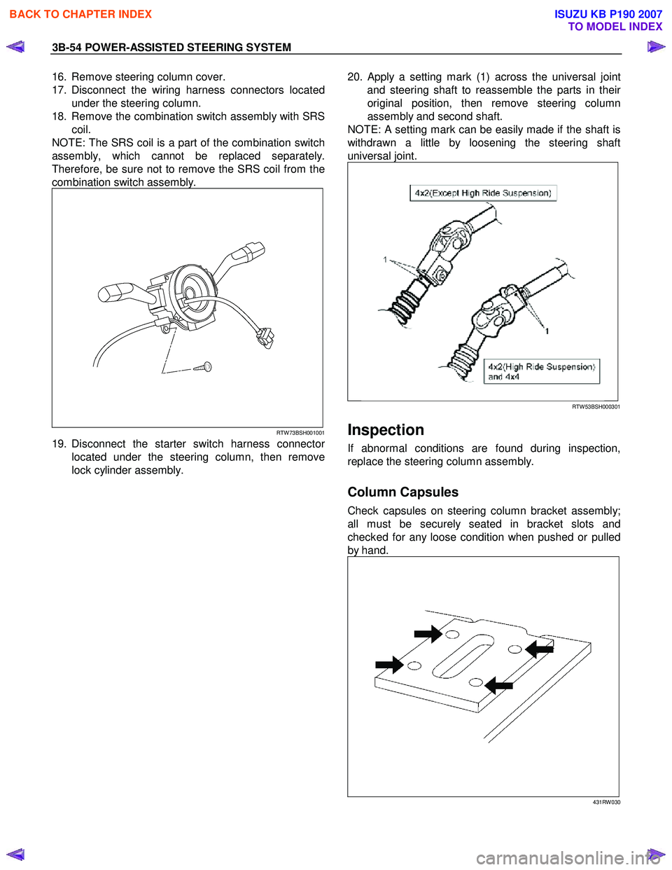
18. Remove the combination switch assembly with SRS coil.
NOTE: The SRS coil is a part of the combination switch
assembly, which cannot be replaced separately.
Therefore, be sure not to remove the SRS coil from the
combination switch assembly.
RTW 73BSH001001
19. Disconnect the starter switch harness connector
located under the steering column, then remove
lock cylinder assembly.
20.
Apply a setting mark (1) across the universal joint
and steering shaft to reassemble the parts in thei
r
original position, then remove steering column
assembly and second shaft.
NOTE: A setting mark can be easily made if the shaft is
withdrawn a little by loosening the steering shaft
universal joint.
RTW 53BSH000301
Inspection
If abnormal conditions are found during inspection,
replace the steering column assembly.
Column Capsules
Check capsules on steering column bracket assembly;
all must be securely seated in bracket slots and
checked for any loose condition when pushed or pulled
by hand.
431RW 030
BACK TO CHAPTER INDEX
TO MODEL INDEX
ISUZU KB P190 2007
Page 316 of 6020
POWER-ASSISTED STEERING SYSTEM 3B-55
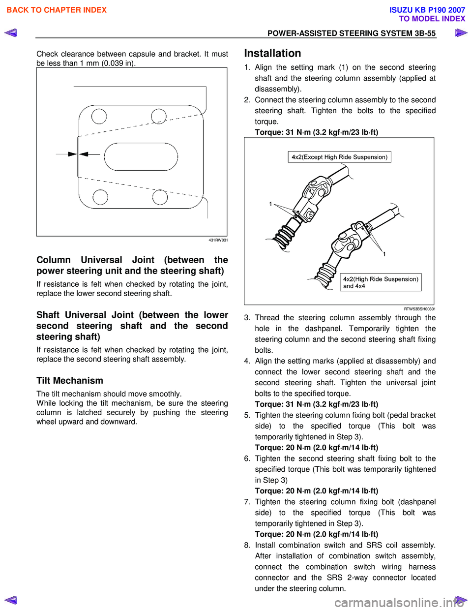
Check clearance between capsule and bracket. It must
be less than 1 mm (0.039 in).
431RW 031
Column Universal Joint (between the
power steering unit and the steering shaft)
If resistance is felt when checked by rotating the joint,
replace the lower second steering shaft.
Shaft Universal Joint (between the lower
second steering shaft and the second
steering shaft)
If resistance is felt when checked by rotating the joint,
replace the second steering shaft assembly.
Tilt Mechanism
The tilt mechanism should move smoothly.
W hile locking the tilt mechanism, be sure the steering
column is latched securely by pushing the steering
wheel upward and downward.
Installation
1. Align the setting mark (1) on the second steering
shaft and the steering column assembly (applied at
disassembly).
2. Connect the steering column assembly to the second steering shaft. Tighten the bolts to the specified
torque.
Torque: 31 N ⋅
⋅⋅
⋅
m (3.2 kgf ⋅
⋅⋅
⋅
m/23 lb ⋅
⋅⋅
⋅
ft)
RTW 53BSH00301
3. Thread the steering column assembly through the
hole in the dashpanel. Temporarily tighten the
steering column and the second steering shaft fixing
bolts.
4.
Align the setting marks (applied at disassembly) and
connect the lower second steering shaft and the
second steering shaft. Tighten the universal joint
bolts to the specified torque.
Torque: 31 N ⋅
⋅⋅
⋅
m (3.2 kgf ⋅
⋅⋅
⋅
m/23 lb ⋅
⋅⋅
⋅
ft)
5. Tighten the steering column fixing bolt (pedal bracket side) to the specified torque (This bolt was
temporarily tightened in Step 3).
Torque: 20 N ⋅
⋅⋅
⋅
m (2.0 kgf ⋅
⋅⋅
⋅
m/14 lb ⋅
⋅⋅
⋅
ft)
6. Tighten the second steering shaft fixing bolt to the specified torque (This bolt was temporarily tightened
in Step 3)
Torque: 20 N ⋅
⋅⋅
⋅
m (2.0 kgf ⋅
⋅⋅
⋅
m/14 lb ⋅
⋅⋅
⋅
ft)
7. Tighten the steering column fixing bolt (dashpanel side) to the specified torque (This bolt was
temporarily tightened in Step 3).
Torque: 20 N ⋅
⋅⋅
⋅
m (2.0 kgf ⋅
⋅⋅
⋅
m/14 lb ⋅
⋅⋅
⋅
ft)
8. Install combination switch and SRS coil assembly.
After installation of combination switch assembly,
connect the combination switch wiring harness
connector and the SRS 2-way connector located
under the steering column.
BACK TO CHAPTER INDEX
TO MODEL INDEX
ISUZU KB P190 2007
Page 426 of 6020
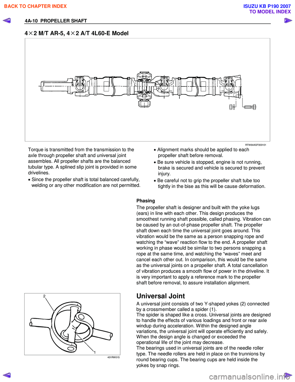
4A-10 PROPELLER SHAFT
4×
××
×
2 M/T AR-5, 4 ×
××
×
2 A/T 4L60-E Model
RTW 64ASF000101
Torque is transmitted from the transmission to the
axle through propeller shaft and universal joint
assembles. All propeller shafts are the balanced
tubular type. A splined slip joint is provided in some
drivelines.
• Since the propeller shaft is total balanced carefully,
welding or any other modification are not permitted.
•
Alignment marks should be applied to each
propeller shaft before removal.
• Be sure vehicle is stopped, engine is not running,
brake is secured and vehicle is secured to prevent
injury.
• Be careful not to grip the propeller shaft tube too
tightly in the bise as this will be cause deformation.
Phasing
The propeller shaft is designer and built with the yoke lugs
(ears) in line with each other. This design produces the
smoothest running shaft possible, called phasing. Vibration can
be caused by an out-of-phase propeller shaft. The propeller
shaft down each time the universal joint goes around. This
vibration would be the same as a person snapping rope and
watching the “wave” reaction flow to the end. A propeller shaft
working in phase would be similar to two persons snapping a
rope at the same time, and watching the “waves” meet and
cancel each other out. In comparison, this would be the same
as the universal joints on a propeller shaft. A total cancellation
of vibration produces a smooth flow of power in the driveline. It
is very important to apply a reference mark to the propeller
shaft before removal, to assure installation alignment.
401RW 015
Universal Joint
A universal joint consists of two Y-shaped yokes (2) connected
by a crossmember called a spider (1).
The spider is shaped like a cross. Universal joints are designed
to handle the effects of various loadings and front or rear axle
windup during acceleration. W ithin the designed angle
variations, the universal joint will operate efficiently and safely.
W hen the design angle is changed or exceeded the
operational life of the joint may decrease.
The bearings used in universal joints are of the needle roller
type. The needle rollers are held in place on the trunnions by
round bearing cups. The bearing cups are held inside the
yokes by snap rings.
BACK TO CHAPTER INDEX
TO MODEL INDEX
ISUZU KB P190 2007
Page 481 of 6020
REAR AXLE 4B-37
Reassembly
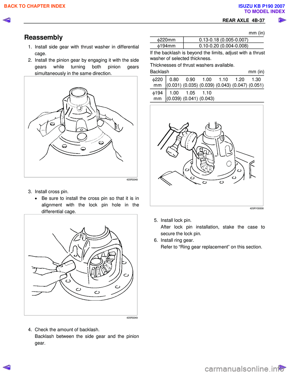
1. Install side gear with thrust washer in differential
cage.
2. Install the pinion gear by engaging it with the side gears while turning both pinion gears
simultaneously in the same direction.
425RS048
3. Install cross pin. • Be sure to install the cross pin so that it is in
alignment with the lock pin hole in the
differential cage.
425RS049
4. Check the amount of backlash.
Backlash between the side gear and the pinion gear.
mm (in)
φ220mm 0.13-0.18 (0.005-0.007)
φ194mm 0.10-0.20 (0.004-0.008)
If the backlash is beyond the limits, adjust with a thrust
washer of selected thickness.
Thicknesses of thrust washers available.
Backlash mm (in)
φ220
mm 0.80
(0.031) 0.90
(0.035) 1.00
(0.039) 1.10
(0.043) 1.20
(0.047) 1.30
(0.051)
φ 194
mm 1.00
(0.039) 1.05
(0.041) 1.10
(0.043)
425RY00008
5. Install lock pin.
After lock pin installation, stake the case to
secure the lock pin.
6. Install ring gear.
Refer to “Ring gear replacement” on this section.
BACK TO CHAPTER INDEX
TO MODEL INDEX
ISUZU KB P190 2007