inflation pressure ISUZU KB P190 2007 Workshop Repair Manual
[x] Cancel search | Manufacturer: ISUZU, Model Year: 2007, Model line: KB P190, Model: ISUZU KB P190 2007Pages: 6020, PDF Size: 70.23 MB
Page 251 of 6020
FRONT ALIGNMENT 3A-3
Inspection
Before making any adjustments affecting caster, camber or
toe-in, the following front end inspection should be made.
1. Inspect the tires for proper inflation pressure. Refer to
Main Data and Specifications in W heel and Tire System section.
2. Make sure that the vehicle is in an unladen condition (W ith no passengers or loading).
3. Make sure that the spare tire is installed at the normal position.
4. Inspect the front wheel bearings for proper adjustment. Refer to Front Hub and Disc Overhaul in Suspension
section.
5. Inspect the ball joints and tie rod ends. If excessive looseness is noted, correct before adjusting. Refer to
Steering Linkage in this section.
6. Inspect the wheel and tires for run-out. Refer to W heel Replacement in W heel and Tire System section.
7. Inspect the trim height. If not within specifications, the correction must be made before adjusting caster.
8. Inspect the steering unit for looseness at the frame.
9. Inspect shock absorbers for leaks or any noticeable noise. Refer to Shock Absorber in Suspension section.
10. Inspect the control arms or stabilizer bar attachment fo
r
looseness. Refer to Suspension section.
11. Inspect the front end alignment using alignment equipment. Follow the manufacturer’s instructions.
12. Park the vehicle on a level surface.
BACK TO CHAPTER INDEX
TO MODEL INDEX
ISUZU KB P190 2007
Page 261 of 6020
FRONT ALIGNMENT 3A-13
RTW 53ASH000301
FRT Buffer clearance (Reference Data) mm(in)
4×2 (High ride suspension), 4 ×4
29.7(1.17)
Adjustment
Adjust the trim height by means of the adjusting bolt on the
height control arms.
1. Check and adjust the tire inflation pressures.
2. Park the vehicle on level ground and move the front of the vehicle up and down several times to settle the suspension.
410RS001
3. Make necessary adjustments with the adjusting bolt on the
height control arms.
RTW 63ASH000101
RR Buffer clearance (Reference Data)
mm(in)
4×2 (High ride suspension), 4 ×4
80.0 (3.15)
BACK TO CHAPTER INDEX
TO MODEL INDEX
ISUZU KB P190 2007
Page 404 of 6020
3D-20 REAR SUSPENSION
4. HARSHNESS
Checkpoint Problem Countermeasure
Bushings in suspension
System
Tire inflation pressure
Retighten or replace
Replace
Adjust
Loosen or broken
Defective
Incorrect
Tires for out of balance
Adjust or replace
Replace tires
Incorrect
Noise does not have any
specific pattern
OK NG
NG
NG
NG
NG
OK
OK Road test vehicle(Noise has a
certain pattern)
BACK TO CHAPTER INDEX
TO MODEL INDEX
ISUZU KB P190 2007
Page 409 of 6020
WHEELS AND TIRES 3E-5
TIRE PRESSURE LABEL (LOCATION: DRIVERS DOOR OR FRAME OF DRIVERS DOOR)
4 ×
××
×
2 Except High Ride Suspension
SEE OW NERS AND
DRIVERS MANUAL FOR
ADDITIONAL INFORMATION
Tire Size Wheel Size Tire inflation pressure
KPa (kgf/cm
2/psi)
Front & Rear Front & Rear Front Rear
195R14C 8PR 14X5.5JJ 245 (2.5/36) 441 (4.5/64)
215/70R15C 15X6.5JJ 221 (2.25/32) 368 (3.75/53)
4 ×
××
×
2 High Ride Suspension, 4 ×
××
×
4
SEE OW NERS AND
DRIVERS MANUAL FOR
ADDITIONAL INFORMATION
Tire Size Wheel Size Tire inflation pressure
KPa (kgf/cm
2/psi)
Front & Rear Front & Rear Front Rear
225/75R15C 15X6.5JJ 221 (2.25/32) 319 (3.25/46)
245/70R16 16X7JJ 200 (2.0/28) 270 (2.8/40)
Note:
•
••
•
The air pressure of the tire should be maintained as indicated in the label instruction on the driver's
door or frame of driver's door.
Lower pressure can cause burst and adverse vehicle handling.
On the other hand, higher pressure can cause shock-burst and reduce gripping effect.
BACK TO CHAPTER INDEX
TO MODEL INDEX
ISUZU KB P190 2007
Page 2008 of 6020
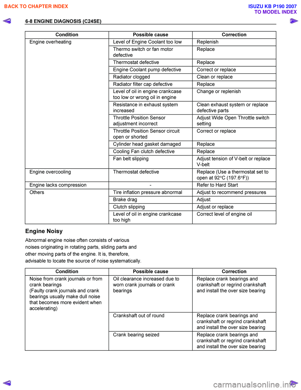
6-8 ENGINE DIAGNOSIS (C24SE)
Condition Possible cause Correction
Engine overheating Level of Engine Coolant too low Replenish
Thermo switch or fan motor
defective Replace
Thermostat
defective Replace
Engine Coolant pump defective Correct or replace
Radiator clogged Clean or replace
Radiator filter cap defective Replace
Level of oil in engine crankcase
too low or wrong oil in engine Change or replenish
Resistance in exhaust system
increased Clean exhaust system or replace
defective parts
Throttle Position Sensor
adjustment incorrect Adjust Wide Open Throttle switch
setting
Throttle Position Sensor circuit
open or shorted Correct or replace
Cylinder head gasket damaged Replace
Cooling Fan clutch defective Replace
Fan belt slipping Adjust tension of V-belt or replace
V-belt
Engine overcooling Thermostat defective Replace (Use a thermostat set to
open at 92 °C (197.6 °F))
Engine lacks compression - Refer to Hard Start
Others Tire inflation pressure abnormal Adjust to recommend pressures
Brake drag Adjust
Clutch slipping Adjust or replace
Level of oil in engine crankcase
too high Correct level of engine oil
Engine Noisy
Abnormal engine noise often consists of various
noises originating in rotating parts, sliding parts and
other moving parts of the engine. It is, therefore,
advisable to locate the source of noise systematically.
Condition Possible cause Correction
Noise from crank journals or from
crank bearings
(Faulty crank journals and crank
bearings usually make dull noise
that becomes more evident when
accelerating) Oil clearance increased due to
worn crank journals or crank
bearings Replace crank bearings and
crankshaft or regrind crankshaft
and install the over size bearing
Crankshaft out of round Replace crank bearings and
crankshaft or regrind crankshaft
and install the over size bearing
Crank bearing seized Replace crank bearings and
crankshaft or regrind crankshaft
and install the over size bearing
BACK TO CHAPTER INDEX
TO MODEL INDEX
ISUZU KB P190 2007
Page 5111 of 6020
ELECTRICAL-BODY AND CHASSIS 8A-173
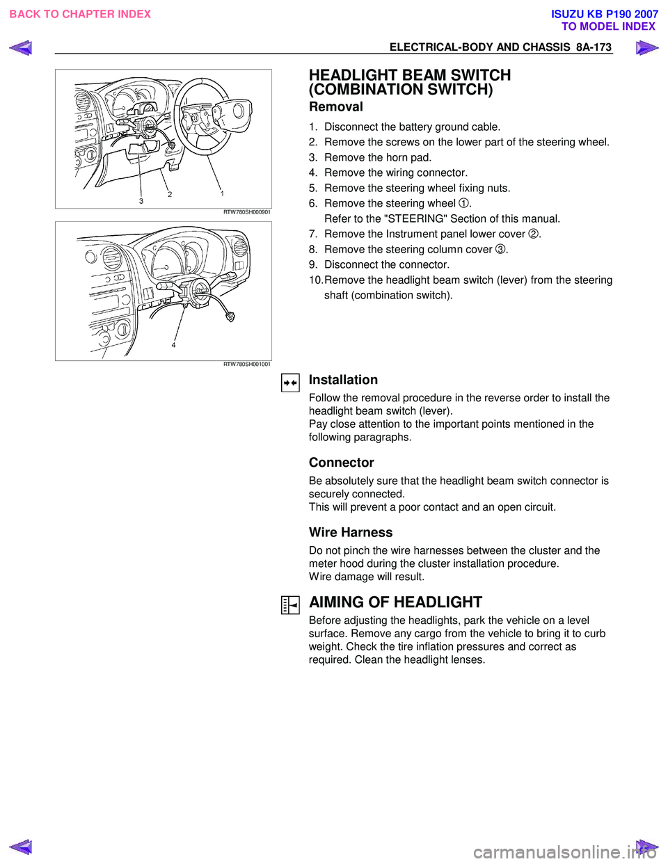
RTW 780SH000901
RTW 780SH001001
HEADLIGHT BEAM SWITCH
(COMBINATION SWITCH)
Removal
1. Disconnect the battery ground cable.
2. Remove the screws on the lower part of the steering wheel.
3. Remove the horn pad.
4. Remove the wiring connector.
5. Remove the steering wheel fixing nuts.
6. Remove the steering wheel
1.
Refer to the "STEERING" Section of this manual.
7. Remove the Instrument panel lower cover
2.
8. Remove the steering column cover
3.
9. Disconnect the connector.
10. Remove the headlight beam switch (lever) from the steering shaft (combination switch).
Installation
Follow the removal procedure in the reverse order to install the
headlight beam switch (lever).
Pay close attention to the important points mentioned in the
following paragraphs.
Connector
Be absolutely sure that the headlight beam switch connector is
securely connected.
This will prevent a poor contact and an open circuit.
Wire Harness
Do not pinch the wire harnesses between the cluster and the
meter hood during the cluster installation procedure.
W ire damage will result.
AIMING OF HEADLIGHT
Before adjusting the headlights, park the vehicle on a level
surface. Remove any cargo from the vehicle to bring it to curb
weight. Check the tire inflation pressures and correct as
required. Clean the headlight lenses.
BACK TO CHAPTER INDEX TO MODEL INDEXISUZU KB P190 2007
Page 5115 of 6020
ELECTRICAL-BODY AND CHASSIS 8A-177
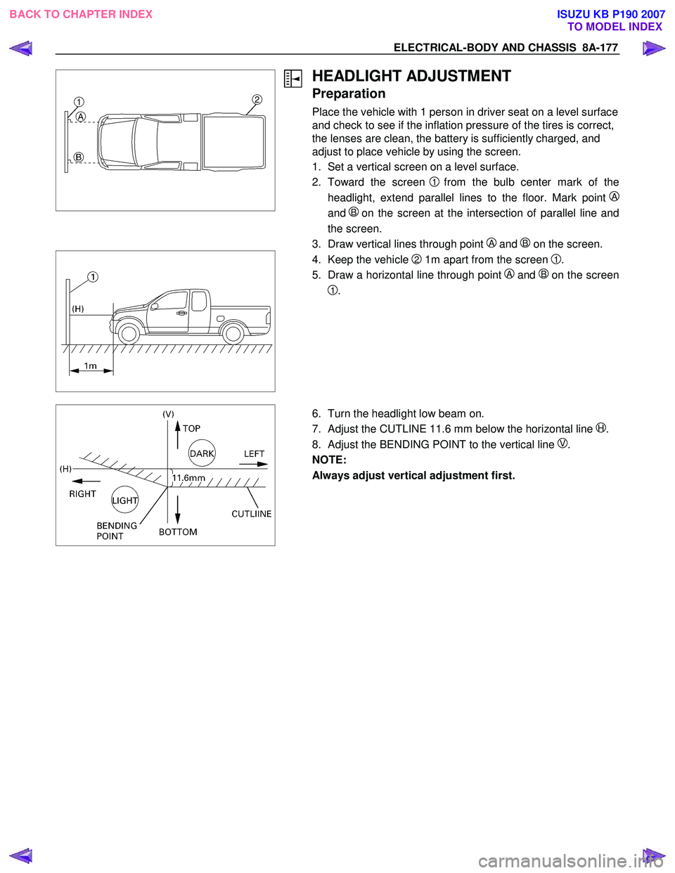
HEADLIGHT ADJUSTMENT
Preparation
Place the vehicle with 1 person in driver seat on a level surface
and check to see if the inflation pressure of the tires is correct,
the lenses are clean, the battery is sufficiently charged, and
adjust to place vehicle by using the screen.
1. Set a vertical screen on a level surface.
2. Toward the screen
1from the bulb center mark of the
headlight, extend parallel lines to the floor. Mark point
A
and B on the screen at the intersection of parallel line and
the screen.
3. Draw vertical lines through point
A and B on the screen.
4. Keep the vehicle 2 1m apart from the screen 1.
5. Draw a horizontal line through point
A and Bon the screen
1.
6. Turn the headlight low beam on.
7. Adjust the CUTLINE 11.6 mm below the horizontal line
H.
8. Adjust the BENDING POINT to the vertical line
V.
NOTE:
Always adjust vertical adjustment first.
BACK TO CHAPTER INDEX TO MODEL INDEXISUZU KB P190 2007