lane assist ISUZU KB P190 2007 Workshop Repair Manual
[x] Cancel search | Manufacturer: ISUZU, Model Year: 2007, Model line: KB P190, Model: ISUZU KB P190 2007Pages: 6020, PDF Size: 70.23 MB
Page 3728 of 6020

Powertrain Interface Module – V6 Page 6E1–67
10.3 Tachometer Diagnostics
Circuit Description
The powertrain interface module (PIM) receives the tachomer signal from the engine control module (ECM), it is then
sent to the instrument cluster by the PIM via a hard wired connection to drive the tachometer which displays the engine
RPM. Some of these components do not set a DTC, in the event of a component failure. The following diagnostic
procedures are devised to assist in these cases.
Additional Information
• Refer to 7.2 Diagnostic System Check to monitor DTC’s.
• Refer to 8A Electrical Body and Chassis for the following information:
• ECM wiring diagram.
• Refer to 6 W iring Diagram and Connector Chart for the following information:
• PIM connector illustration and terminal assignment, and
• PIM wiring diagram.
• For intermittent faults, refer to Intermittent Fault Conditions.
• Check for an intermittent fault in the wiring harness or connectors, if a fault cannot be found the system is
serviceable.
Since fault conditions in a wiring connector may trigger DTCs, always test the connectors related to this diagnostic
procedure for shorted terminals or poor wiring connection before replacing any component. Refer to 8A Electrical - Body
and Chassis for information on electrical fault diagnosis.
Test Description
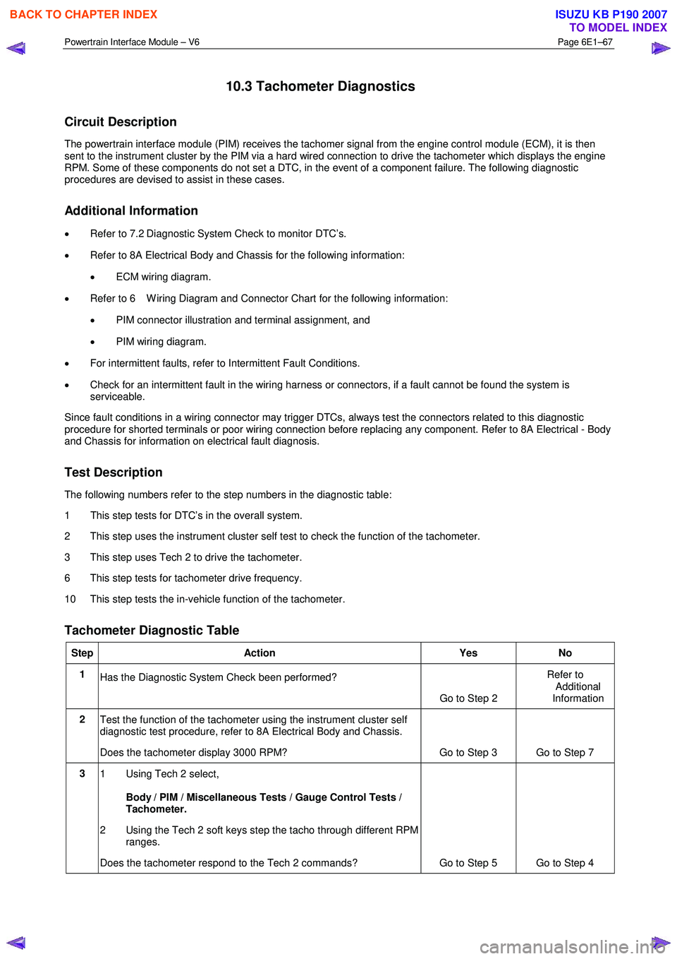
The following numbers refer to the step numbers in the diagnostic table:
1 This step tests for DTC’s in the overall system.
2 This step uses the instrument cluster self test to check the function of the tachometer.
3 This step uses Tech 2 to drive the tachometer.
6 This step tests for tachometer drive frequency.
10 This step tests the in-vehicle function of the tachometer.
Tachometer Diagnostic Table
Step Action Yes No
1
Has the Diagnostic System Check been performed?
Go to Step 2 Refer to
Additional
Information
2 Test the function of the tachometer using the instrument cluster self
diagnostic test procedure, refer to 8A Electrical Body and Chassis.
Does the tachometer display 3000 RPM? Go to Step 3 Go to Step 7
3 1 Using Tech 2 select,
Body / PIM / Miscellaneous Tests / Gauge Control Tests /
Tachometer.
2 Using the Tech 2 soft keys step the tacho through different RPM ranges.
Does the tachometer respond to the Tech 2 commands? Go to Step 5 Go to Step 4
BACK TO CHAPTER INDEX
TO MODEL INDEX
ISUZU KB P190 2007
Page 3771 of 6020

Automatic Transmission – 4L60E – General Information Page 7C1–11
4 Transmission Definitions and
Abbreviations
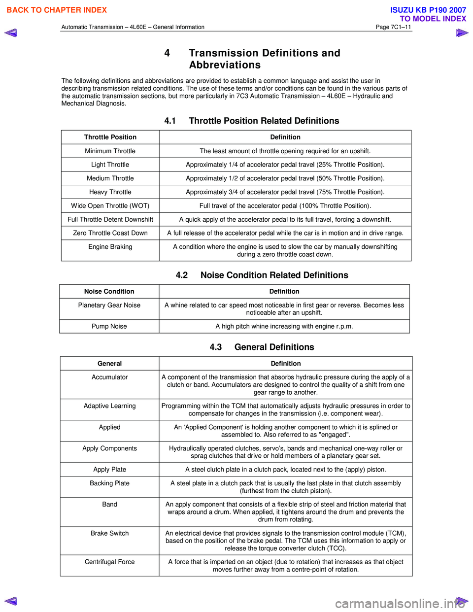
The following definitions and abbreviations are provided to establish a common language and assist the user in
describing transmission related conditions. The use of these terms and/or conditions can be found in the various parts of
the automatic transmission sections, but more particularly in 7C3 Automatic Transmission – 4L60E – Hydraulic and
Mechanical Diagnosis.
4.1 Throttle Position Related Definitions
Throttle Position Definition
Minimum Throttle The least amount of throttle opening required for an upshift.
Light Throttle Approximately 1/4 of accelerator pedal travel (25% Throttle Position).
Medium Throttle Approximately 1/2 of accelerator pedal travel (50% Throttle Position).
Heavy Throttle Approximately 3/4 of accelerator pedal travel (75% Throttle Position).
Wide Open Throttle (WOT) Full travel of the accelerator pedal (100% Throttle Position).
Full Throttle Detent Downshift A quick apply of the accelerator pedal to its full travel, forcing a downshift.
Zero Throttle Coast Down A full release of the accelerator pedal while the car is in motion and in drive range.
Engine Braking A condition where the engine is used to slow the car by manually downshifting
during a zero throttle coast down.
4.2 Noise Condition Related Definitions
Noise Condition Definition
Planetary Gear Noise A whine related to car speed most noticeable in first gear or reverse. Becomes less
noticeable after an upshift.
Pump Noise A high pitch whine increasing with engine r.p.m.
4.3 General Definitions
General Definition
Accumulator A component of the transmission that absorbs hydraulic pressure during the apply of a
clutch or band. Accumulators are designed to control the quality of a shift from one gear range to another.
Adaptive Learning Programming within the TCM that automatically adjusts hydraulic pressures in order to compensate for changes in the transmission (i.e. component wear).
Applied An 'Applied Component' is holding another component to which it is splined or
assembled to. Also referred to as "engaged".
Apply Components Hydraulically operated clutches, servo’s, bands and mechanical one-way roller or
sprag clutches that drive or hold members of a planetary gear set.
Apply Plate A steel clutch plate in a clutch pack, located next to the (apply) piston.
Backing Plate A steel plate in a clutch pack that is usually the last plate in that clutch assembly
(furthest from the clutch piston).
Band An apply component that consists of a flexible strip of steel and friction material that
wraps around a drum. When applied, it tightens around the drum and prevents the drum from rotating.
Brake Switch An electrical device that provides signals to the transmission control module (TCM),
based on the position of the brake pedal. The TCM uses this information to apply or
release the torque converter clutch (TCC).
Centrifugal Force A force that is imparted on an object (due to rotation) that increases as that object moves further away from a centre-point of rotation.
BACK TO CHAPTER INDEX
TO MODEL INDEX
ISUZU KB P190 2007