turn signal ISUZU KB P190 2007 Workshop Repair Manual
[x] Cancel search | Manufacturer: ISUZU, Model Year: 2007, Model line: KB P190, Model: ISUZU KB P190 2007Pages: 6020, PDF Size: 70.23 MB
Page 212 of 6020
SHEET METAL 2B-15
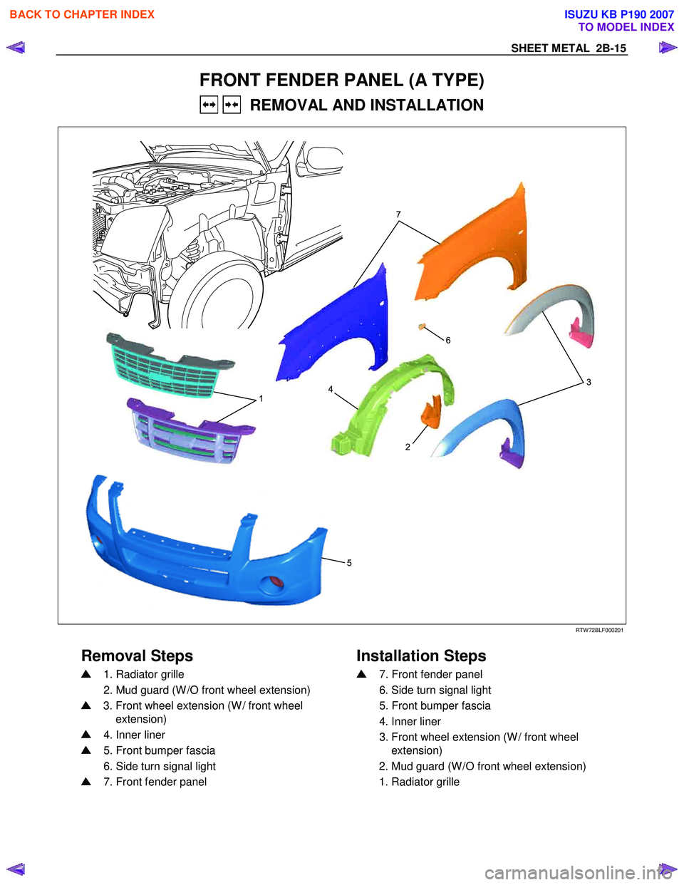
FRONT FENDER PANEL (A TYPE)
REMOVAL AND INSTALLATION
1
52
4
6
3
7
RTW 72BLF000201
Removal Steps
Installation Steps
1. Radiator grille
2. Mud guard (W /O front wheel extension)
3. Front wheel extension (W / front wheel
extension)
4. Inner liner
5. Front bumper fascia
6. Side turn signal light
7. Front fender panel
7. Front fender panel
6. Side turn signal light
5. Front bumper fascia
4. Inner liner
3. Front wheel extension (W / front wheel
extension)
2. Mud guard (W /O front wheel extension)
1. Radiator grille
BACK TO CHAPTER INDEX
TO MODEL INDEX
ISUZU KB P190 2007
Page 215 of 6020
2B-18 SHEET METAL
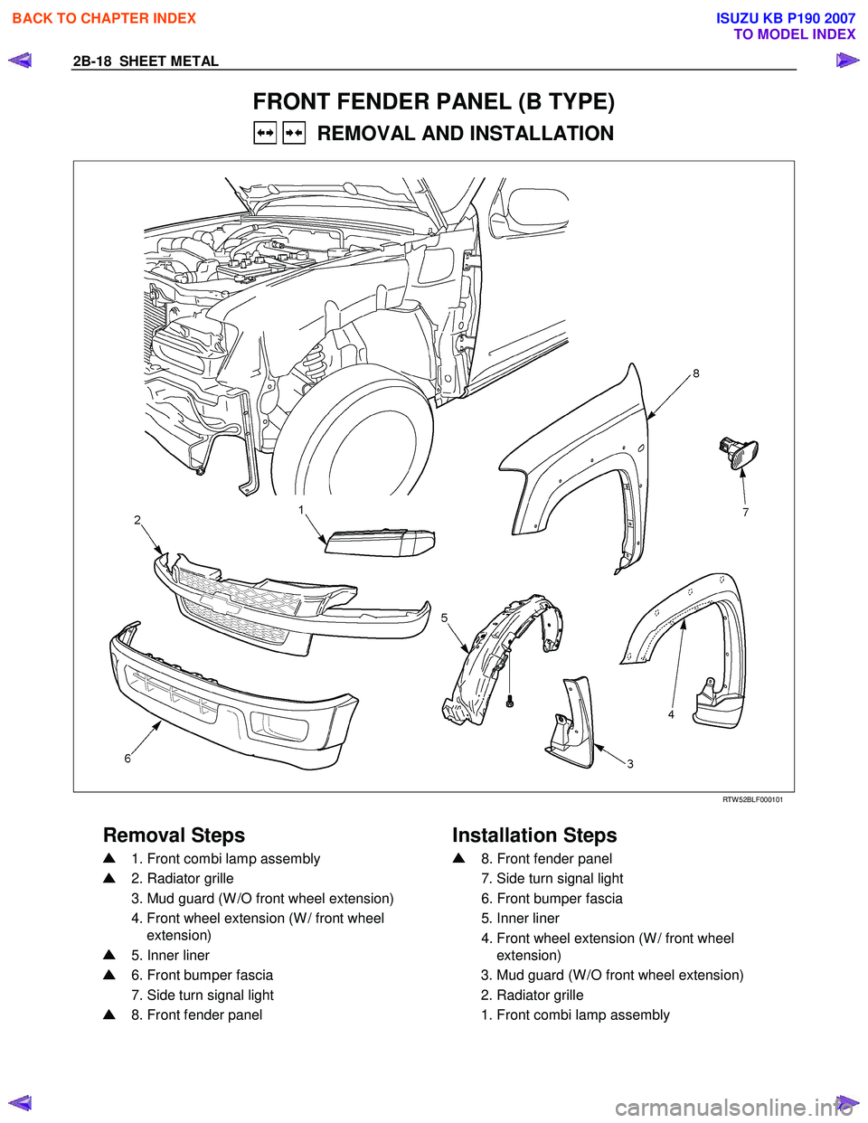
FRONT FENDER PANEL (B TYPE)
REMOVAL AND INSTALLATION
RTW 52BLF000101
Removal Steps Installation Steps
1. Front combi lamp assembly
2. Radiator grille
3. Mud guard (W /O front wheel extension)
4. Front wheel extension (W / front wheel
extension)
5. Inner liner
6. Front bumper fascia
7. Side turn signal light
8. Front fender panel
8. Front fender panel
7. Side turn signal light
6. Front bumper fascia
5. Inner liner
4. Front wheel extension (W / front wheel
extension)
3. Mud guard (W /O front wheel extension)
2. Radiator grille
1. Front combi lamp assembly
BACK TO CHAPTER INDEX
TO MODEL INDEX
ISUZU KB P190 2007
Page 379 of 6020
3C-58 FRONT SUSPENSION
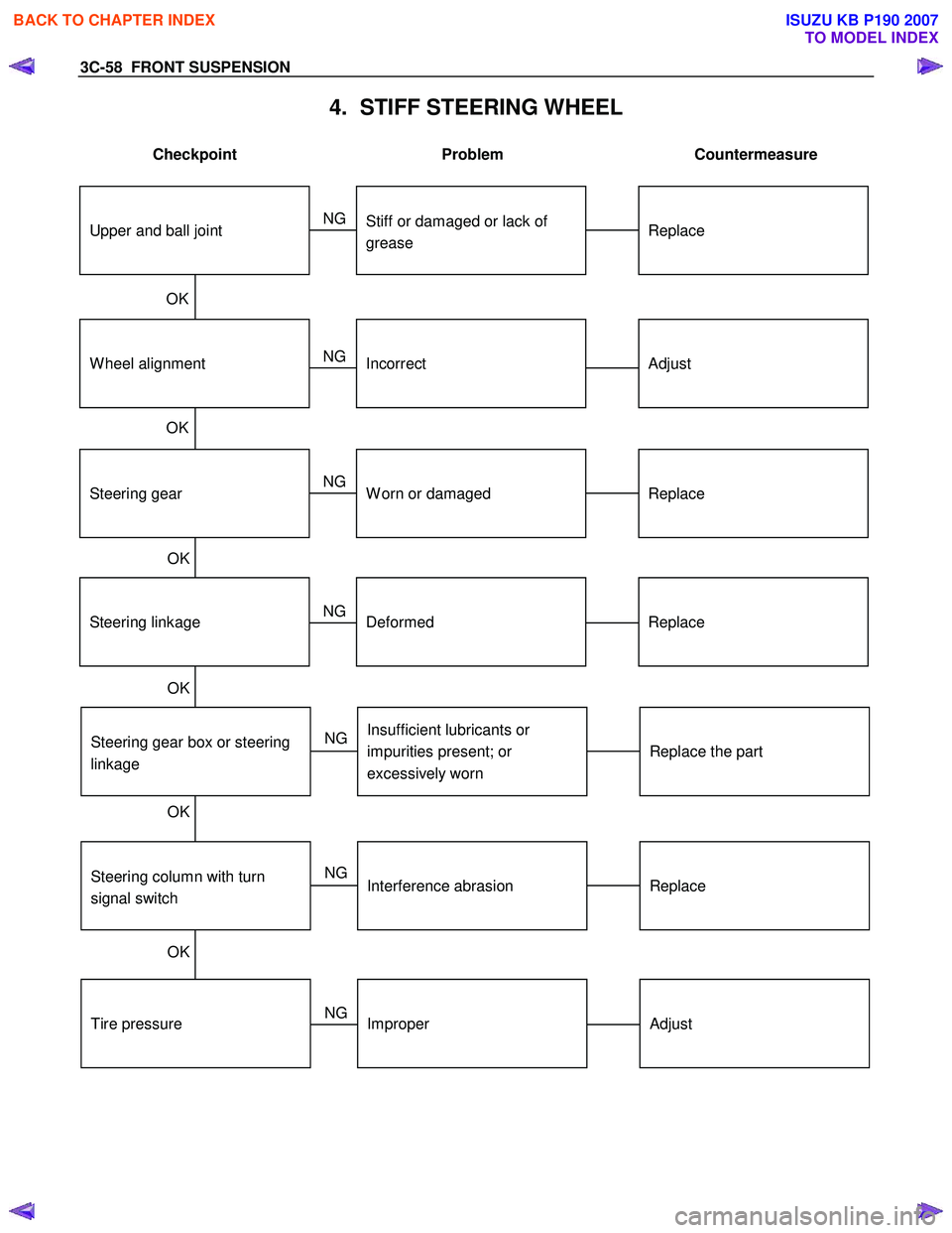
4. STIFF STEERING WHEEL
Checkpoint Problem Countermeasure
Steering gear box or steering
linkage
Steering linkage
Steering gear
W heel alignment
Replace the part
Replace
Replace
Adjust
Insufficient lubricants or
impurities present; or
excessively worn
Deformed
W orn or damaged
Incorrect
Replace
Stiff or damaged or lack of
grease
OK
OK
OK
OK
OK
NG
NG
NG
NG
NG
OK
Upper and ball joint
Steering column with turn
signal switch
Replace
Interference abrasion
NG
Tire pressure
Adjust
Improper
NG
BACK TO CHAPTER INDEX
TO MODEL INDEX
ISUZU KB P190 2007
Page 595 of 6020
BRAKE CON TROL SY STE M 5 A-2
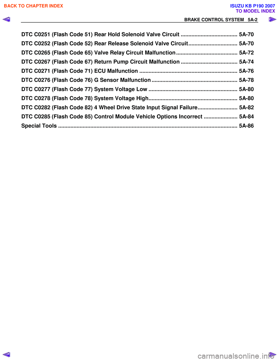
DTC C0251 (Flash Code 51) Rear Hold Solenoid Valve Circuit ..................................... 5A-70
DTC C0252 (Flash Code 52) Rear Release Solenoid Valve Circuit ................................ 5A-70
DTC C0265 (Flash Code 65) Valve Relay Circuit Malfunction ........................................ 5A-72
DTC C0267 (Flash Code 67) Return Pump Circuit Malfunction ..................................... 5A-74
DTC C0271 (Flash Code 71) ECU Malfunction ................................................................ 5A-76
DTC C0276 (Flash Code 76) G Sensor Malfunction ........................................................ 5A-78
DTC C0277 (Flash Code 77) System Voltage Low .......................................................... 5A-80
DTC C0278 (Flash Code 78) System Voltage High.......................................................... 5A-80
DTC C0282 (Flash Code 82) 4 Wheel Drive State Input Signal Failure.......................... 5A-82
DTC C0285 (Flash Code 85) Control Module Vehicle Options Incorrect ...................... 5A-84
Special Tools .................................................................................................................. ... 5A-86
BACK TO CHAPTER INDEX
TO MODEL INDEX
ISUZU KB P190 2007
Page 615 of 6020
5A-22 BRAKE CONTROL SYSTEM
System Components
Electronic Hydraulic Control Unit (EHCU), four W heel
Speed Sensors, two W arning Lamps, and G sensor.
Electronic Hydraulic Control Unit (EHCU)
The EHCU consists of ABS control circuits, fault
detector, and a fail-safe. It drives the EHCU according
to the signal from each sensor, cancelling ABS to return
to normal braking when a malfunction has occurred in
the ABS.
The EHCU has a self-diagnosing function which can
indicate faulty circuits during diagnosis.
The EHCU is mounted on the engine compartment rear
left side. It consists of a motor, solenoid valves and a
fail safe relay.
Solenoid Valves: Reduces or holds the caliper fluid
pressure for each front brake or both rear brakes
according to the signal sent from the EHCU.
Buffer chamber: Temporarily holds the brake fluid that
returns from the front and rear brake so that pressure of
front brake can be reduced smoothly.
Motor: Drives the pump according to the signal from
EHCU.
Fail safe Relay: W hen failure occurs in ABS.
The power supply to solenoid Valve is cut.
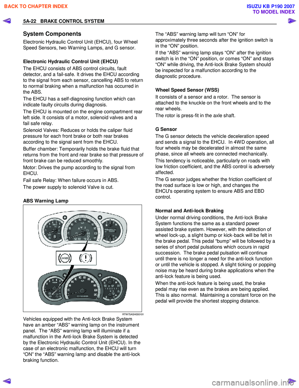
ABS Warning Lamp
RTW 75ASH000101
Vehicles equipped with the Anti-lock Brake System
have an amber “ABS” warning lamp on the instrument
panel. The “ABS” warning lamp will illuminate if a
malfunction in the Anti-lock Brake System is detected
by the Electronic Hydraulic Control Unit (EHCU). In the
case of an electronic malfunction, the EHCU will turn
“ON” the “ABS” warning lamp and disable the anti-lock
braking function.
The “ABS” warning lamp will turn “ON” for
approximately three seconds after the ignition switch is
in the “ON” position.
If the “ABS” warning lamp stays “ON” after the ignition
switch is in the “ON” position, or comes “ON” and stays
“ON” while driving, the Anti-lock Brake System should
be inspected for a malfunction according to the
diagnostic procedure.
Wheel Speed Sensor (WSS)
It consists of a sensor and a rotor. The sensor is
attached to the knuckle on the front wheels and to the
rear wheels.
The rotor is press-fit in the axle shaft.
G Sensor
The G sensor detects the vehicle deceleration speed
and sends a signal to the EHCU. In 4W D operation, all
four wheels may be decelerated in almost the same
phase, since all wheels are connected mechanically.
This tendency is noticeable, particularly on roads with
low friction coefficient, and the ABS control is adversely
affected.
The G sensor judges whether the friction coefficient of
the road surface is low or high, and changes the
EHCU's operating system to ensure ABS and EBD
control.
Normal and Anti-lock Braking
Under normal driving conditions, the Anti-lock Brake
System functions the same as a standard power
assisted brake system. However, with the detection of
wheel lock-up, a slight bump or kick-back will be felt in
the brake pedal. This pedal “bump” will be followed by a
series of short pedal pulsations which occurs in rapid
succession. The brake pedal pulsation will continue
until there is no longer a need for the anti-lock function
or until the vehicle is stopped. A slight ticking or popping
noise may be heard during brake applications when the
anti-lock feature is being used.
W hen the anti-lock feature is being used, the brake
pedal may rise even as the brakes are being applied.
This is also normal. Maintaining a constant force on the
pedal will provide the shortest stopping distance.
BACK TO CHAPTER INDEX
TO MODEL INDEX
ISUZU KB P190 2007
Page 626 of 6020
BRAKE CONTROL SYSTEM 5A-33
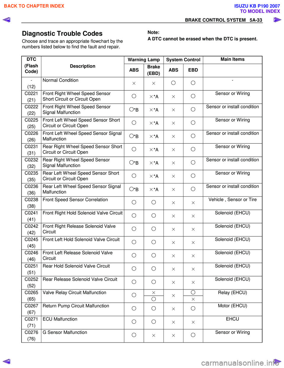
Diagnostic Trouble Codes
Choose and trace an appropriate flowchart by the
numbers listed below to find the fault and repair.
Note:
A DTC cannot be erased when the DTC is present.
Warning Lamp System Control Main Items
DTC
(Flash Code) Description
ABS Brake
(EBD) ABS EBD
-
(12) Normal Condition
× × -
C0221
(21) Front Right W heel Speed Sensor
Short Circuit or Circuit Open ×*A × Sensor or W iring
C0222
(22) Front Right W heel Speed Sensor
Signal Malfunction *B ×*A × Sensor or install condition
C0225
(25) Front Left W heel Speed Sensor Short
Circuit or Circuit Open ×*A × Sensor or W iring
C0226
(26) Front Left W heel Speed Sensor Signal
Malfunction *B ×*A × Sensor or install condition
C0231
(31) Rear Right W heel Speed Sensor Short
Circuit or Circuit Open ×*A × Sensor or W iring
C0232
(32) Rear Right W heel Speed Sensor
Signal Malfunction *B ×*A × Sensor or install condition
C0235
(35) Rear Left W heel Speed Sensor Short
Circuit or Circuit Open ×*A × Sensor or W iring
C0236
(36) Rear Left W heel Speed Sensor Signal
Malfunction *B ×*A × Sensor or install condition
C0238
(38) Front Speed Sensor Correlation
× × Vehicle , Sensor or Tire
C0241
(41) Front Right Hold Solenoid Valve Circuit
× × Solenoid (EHCU)
C0242
(42) Front Right Release Solenoid Valve
Circuit × × Solenoid (EHCU)
C0245
(45) Front Left Hold Solenoid Valve Circuit
× × Solenoid (EHCU)
C0246
(46) Front Left Release Solenoid Valve
Circuit × × Solenoid (EHCU)
C0251
(51) Rear Hold Solenoid Valve Circuit
× × Solenoid (EHCU)
C0252
(52) Rear Release Solenoid Valve Circuit
× × Solenoid (EHCU)
×
C0265
(65) Valve Relay Circuit Malfunction
×
× Relay (EHCU)
C0267
(67) Return Pump Circuit Malfunction
× Motor (EHCU)
C0271
(71) ECU Malfunction
× × EHCU
C0276
(76) G Sensor Malfunction
× × Sensor or W iring
BACK TO CHAPTER INDEX
TO MODEL INDEX
ISUZU KB P190 2007
Page 1071 of 6020
Engine Control System (4JH1) 6E-37
Scan Tool Parameter Units DisplayedTypical Data Value at
Engine Idle
Typical Data Value at 2000
RPM
Glow Relay Command On/Off Off Off
Glow Indicator Lamp Command On/Off Off Off
Malfunction Indicator Lamp (MIL) Command On/Off Off Off
A/C Request Signal On/Off Off Off
A/C Relay Command On/Off Off Off
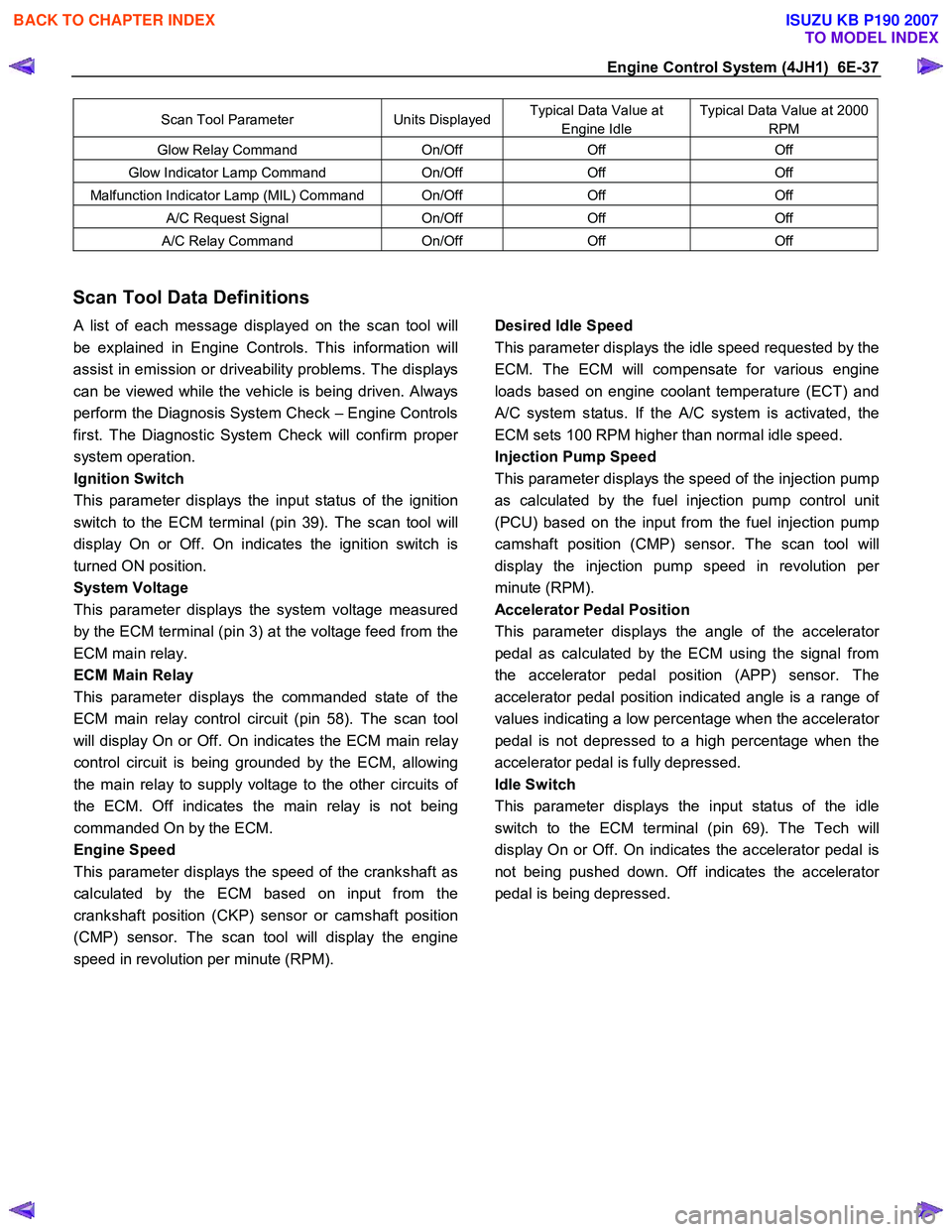
Scan Tool Data Definitions
A list of each message displayed on the scan tool will
be explained in Engine Controls. This information will
assist in emission or driveability problems. The displays
can be viewed while the vehicle is being driven. Always
perform the Diagnosis System Check – Engine Controls
first. The Diagnostic System Check will confirm prope
r
system operation.
Ignition Switch
This parameter displays the input status of the ignition
switch to the ECM terminal (pin 39). The scan tool will
display On or Off. On indicates the ignition switch is
turned ON position.
System Voltage
This parameter displays the system voltage measured
by the ECM terminal (pin 3) at the voltage feed from the
ECM main relay.
ECM Main Relay
This parameter displays the commanded state of the
ECM main relay control circuit (pin 58). The scan tool
will display On or Off. On indicates the ECM main rela
y
control circuit is being grounded by the ECM, allowing
the main relay to supply voltage to the other circuits o
f
the ECM. Off indicates the main relay is not being
commanded On by the ECM.
Engine Speed
This parameter displays the speed of the crankshaft as
calculated by the ECM based on input from the
crankshaft position (CKP) sensor or camshaft position
(CMP) sensor. The scan tool will display the engine
speed in revolution per minute (RPM).
Desired Idle Speed
This parameter displays the idle speed requested by the
ECM. The ECM will compensate for various engine
loads based on engine coolant temperature (ECT) and
A/C system status. If the A/C system is activated, the
ECM sets 100 RPM higher than normal idle speed.
Injection Pump Speed
This parameter displays the speed of the injection pump
as calculated by the fuel injection pump control unit
(PCU) based on the input from the fuel injection pump
camshaft position (CMP) sensor. The scan tool will
display the injection pump speed in revolution pe
r
minute (RPM).
Accelerator Pedal Position
This parameter displays the angle of the accelerato
r
pedal as calculated by the ECM using the signal from
the accelerator pedal position (APP) sensor. The
accelerator pedal position indicated angle is a range o
f
values indicating a low percentage when the accelerator
pedal is not depressed to a high percentage when the
accelerator pedal is fully depressed.
Idle Switch
This parameter displays the input status of the idle
switch to the ECM terminal (pin 69). The Tech will
display On or Off. On indicates the accelerator pedal is
not being pushed down. Off indicates the accelerato
r
pedal is being depressed.
BACK TO CHAPTER INDEX
TO MODEL INDEX
ISUZU KB P190 2007
Page 1072 of 6020
6E-38 Engine Control System (4JH1)
Intake Air Temperature
This parameter displays the temperature of the intake
air based on a voltage input from the intake ai
r
temperature (IAT) sensor to the ECM. The scan tool will
display a low temperature when signal voltage is high,
and high temperature when the signal voltage is low.
Note that the IAT sensor is internal to the mass air flo
w
(MAF) sensor and the MAF sensor is heated.
Engine Coolant Temperature
This parameter displays the temperature of the engine
coolant based on a voltage input from the engine
coolant temperature (ECT) sensor to the ECM. The
scan tool will display a low temperature when the signal
voltage is high, and a high temperature when the signal
voltage is low.
Fuel Temperature
This parameter displays the temperature of the fuel as
calculated by the fuel injection pump control unit (PCU)
using the signal from the fuel temperature sensor inside
of the PCU.
Barometric Pressure
This parameter displays the barometric pressure as
calculated by the ECM using the signal from the
barometric pressure (BARO) sensor inside of the ECM.
Vacuum Pressure Sensor (High altitude
specification only)
This parameter displays the amount of the vacuum
pressure to the turbocharger wastegate valve. W hen a
high vacuum pressure at a low vacuum pressure
amount to the turbocharger wastegate valve. The scan
tool will display doubled barometric pressure when the
ignition is ON with the engine OFF.
Turbocharger Solenoid Command (High altitude
specification only)
This parameter displays the turbocharger solenoid
valuve control duty ratio commanded by the ECM
terminal (pin 96) using the signal from various senso
r
inputs. W hen a low duty ratio, vacuum pressure to the
turbocharger wastegate valve is controlled to increase.
W hen a high duty ratio, vacuum pressure to the
turbochager wastegate valve is controlled to reduce.
EGR Solenoid Command
This parameter displays the EGR solenoid valve control
duty ratio commanded by the ECM terminal (pin 97)
using the signal from engine speed, and injection
volume and various sensor inputs. W hen a small dut
y
ratio, the EGR valve is controlled to close. W hen a large
duty ratio, the EGR valve is controlled to open.
Mass Air Flow Sensor
This parameter displays the air flow into the engine as
calculated by the ECM based on the mass air flo
w
(MAF) sensor input. The scan tool will display a high
value at higher engine speeds, and a low value at idle.
This can be compared to the Desired Mass Air Flow to
determine MAF sensor accuracy, EGR problem o
r
intake problem. Note that the MAF on the scan tool will
only update with the engine running.
Desired Mass Air Flow
This parameter displays a mass air flow desired by the
ECM based on current driving condition.
Actual Injection Quantity
This parameter displays the injection quantity calculated
by the PCU based on the fuel injection solenoid valve
On time which compensated from the timing device
position and fuel temperature inputs. This can be
compared to the Desired Injection Quantity to determine
fuel system problem.
Desired Injection Quantity
This parameter displays an injection quantity desired b
y
the ECM based on current driving condition using target
injection maps.
Actual Injection Timing
This parameter displays the injection timing calculated
by the PCU based on the timing device position which
determined from the crankshaft position sensor and
camshaft position sensor inputs. This can be compared
to the Desired Injection Timing to determine timing
device problem or fuel system problem.
Desired Injection Timing
This parameter displays injection timing desired by the
ECM based on current driving condition using target
injection timing maps. This timing is compensated b
y
engine coolant temperature, altitude and intake ai
r
temperature, etc.
Neutral Switch
This parameter displays the state of the neutral switch
as determined by the ECM terminal (pin 87) based on
an input from the neutral switch or inhibitor switch.
Brake Pedal 1 Switch
This parameter displays the state of the brake pedal as
determined by the ECM terminal (pin 30) based on an
input from the brake pedal 1 switch. This switch turns
On the stop lamps when the brake pedal is depressed.
The scan tool will display Applied when the brake pedal
is depressed.
BACK TO CHAPTER INDEX
TO MODEL INDEX
ISUZU KB P190 2007
Page 1075 of 6020
Engine Control System (4JH1) 6E-41
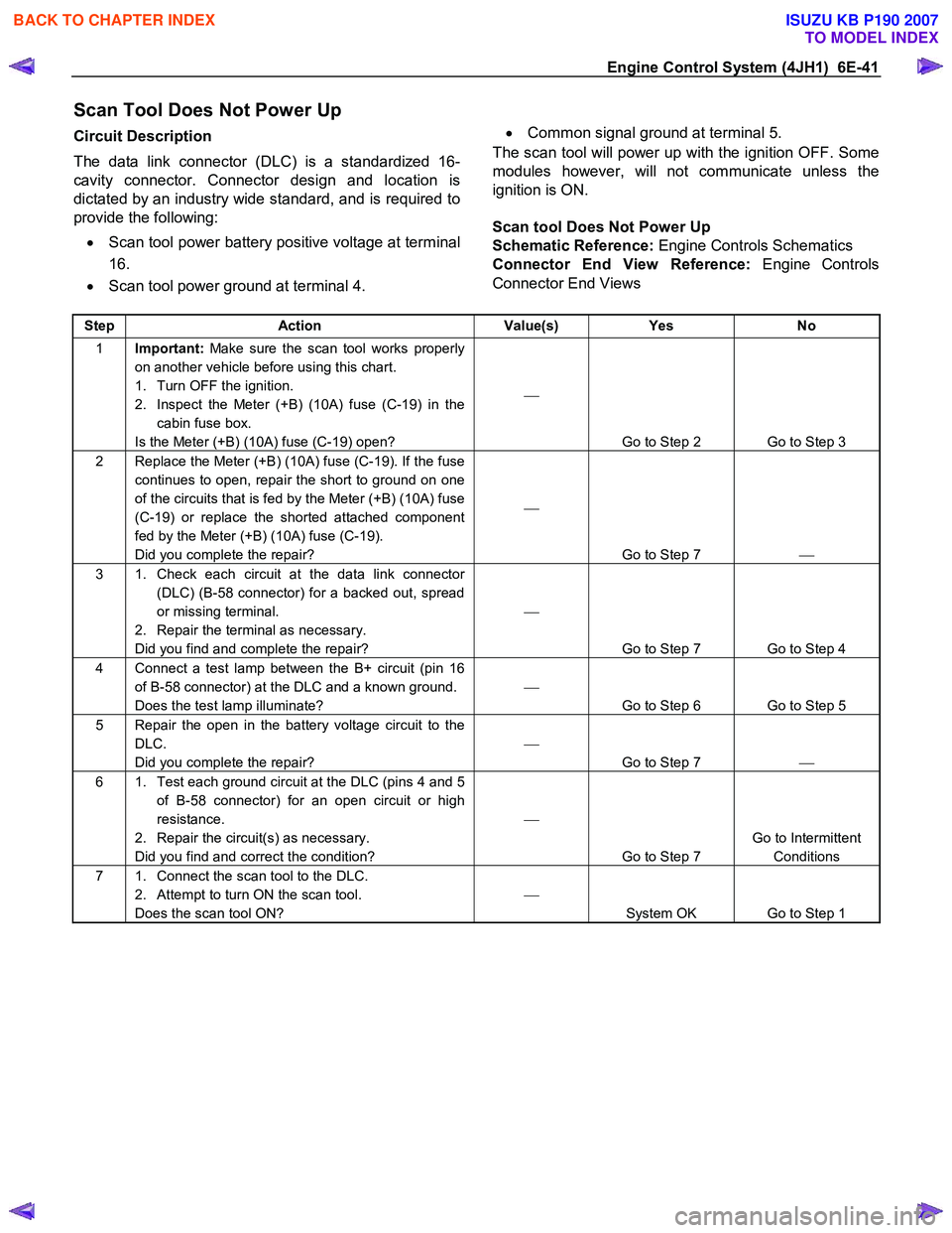
Scan Tool Does Not Power Up
Circuit Description
The data link connector (DLC) is a standardized 16-
cavity connector. Connector design and location is
dictated by an industry wide standard, and is required to
provide the following:
• Scan tool power battery positive voltage at terminal
16.
• Scan tool power ground at terminal 4.
•
Common signal ground at terminal 5.
The scan tool will power up with the ignition OFF. Some
modules however, will not communicate unless the
ignition is ON.
Scan tool Does Not Power Up
Schematic Reference: Engine Controls Schematics
Connector End View Reference: Engine Controls
Connector End Views
Step Action Value(s) Yes No
1 Important: Make sure the scan tool works properly
on another vehicle before using this chart.
1. Turn OFF the ignition.
2. Inspect the Meter (+B) (10A) fuse (C-19) in the cabin fuse box.
Is the Meter (+B) (10A) fuse (C-19) open?
Go to Step 2 Go to Step 3
2 Replace the Meter (+B) (10A) fuse (C-19). If the fuse continues to open, repair the short to ground on one
of the circuits that is fed by the Meter (+B) (10A) fuse
(C-19) or replace the shorted attached component
fed by the Meter (+B) (10A) fuse (C-19).
Did you complete the repair?
Go to Step 7
3 1. Check each circuit at the data link connector
(DLC) (B-58 connector) for a backed out, spread
or missing terminal.
2. Repair the terminal as necessary.
Did you find and complete the repair?
Go to Step 7 Go to Step 4
4 Connect a test lamp between the B+ circuit (pin 16 of B-58 connector) at the DLC and a known ground.
Does the test lamp illuminate?
Go to Step 6 Go to Step 5
5 Repair the open in the battery voltage circuit to the DLC.
Did you complete the repair?
Go to Step 7
6 1. Test each ground circuit at the DLC (pins 4 and 5
of B-58 connector) for an open circuit or high
resistance.
2. Repair the circuit(s) as necessary.
Did you find and correct the condition?
Go to Step 7 Go to Intermittent
Conditions
7 1. Connect the scan tool to the DLC. 2. Attempt to turn ON the scan tool.
Does the scan tool ON?
System OK Go to Step 1
BACK TO CHAPTER INDEX
TO MODEL INDEX
ISUZU KB P190 2007
Page 1097 of 6020
Engine Control System (4JH1) 6E-63
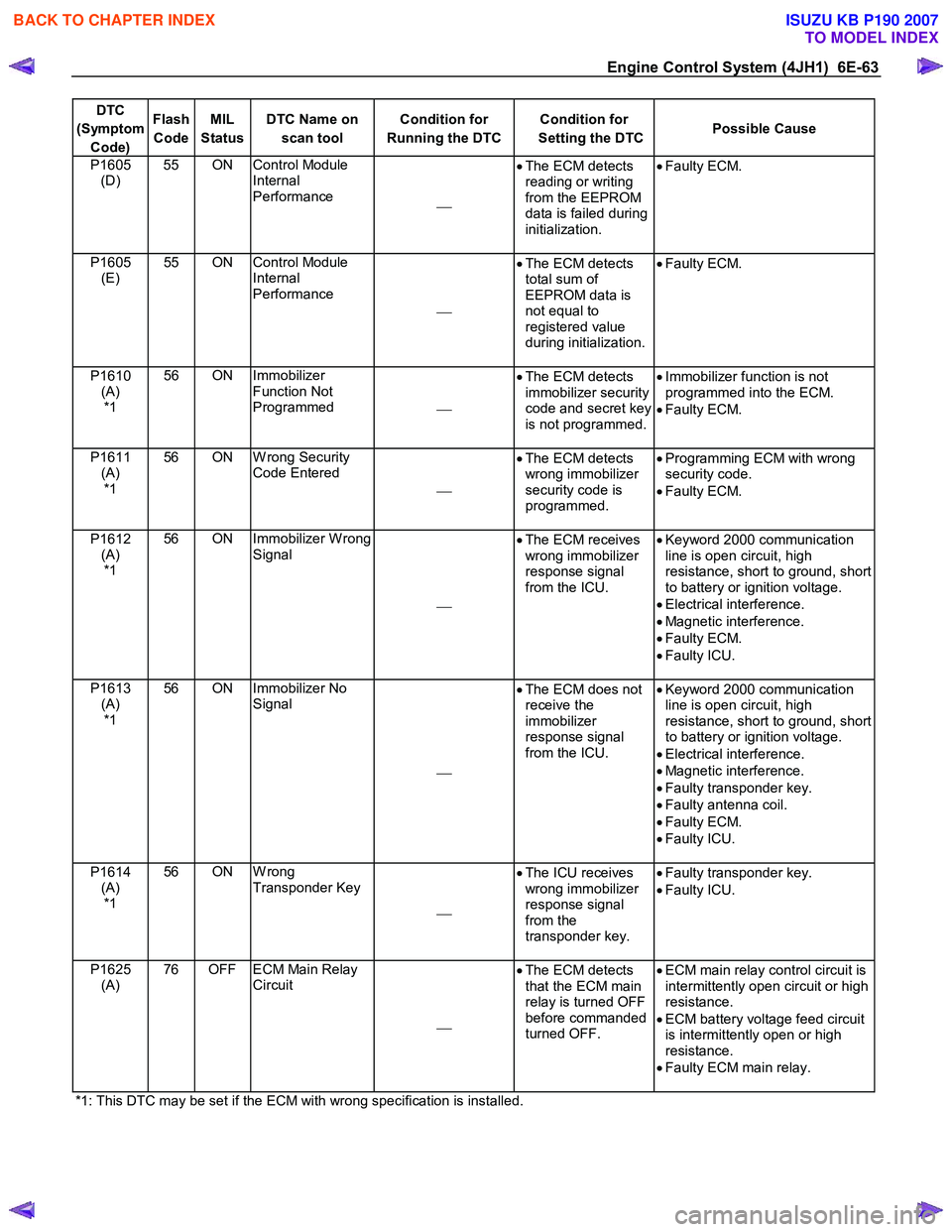
DTC
(Symptom Code) Flash
Code MIL
Status DTC Name on
scan tool Condition for
Running the DTC Condition for
Setting the DTC Possible Cause
P1605
(D) 55 ON Control Module
Internal
Performance •
The ECM detects
reading or writing
from the EEPROM
data is failed during
initialization.
•
Faulty ECM.
P1605
(E) 55 ON Control Module
Internal
Performance
•
The ECM detects
total sum of
EEPROM data is
not equal to
registered value
during initialization.
•
Faulty ECM.
P1610
(A) *1 56 ON Immobilizer
Function Not
Programmed •
The ECM detects
immobilizer security
code and secret key
is not programmed.
•
Immobilizer function is not
programmed into the ECM.
• Faulty ECM.
P1611 (A) *1 56 ON W rong Security
Code Entered
•
The ECM detects
wrong immobilizer
security code is
programmed.
•
Programming ECM with wrong
security code.
• Faulty ECM.
P1612 (A) *1 56 ON Immobilizer W rong
Signal
•
The ECM receives
wrong immobilizer
response signal
from the ICU.
•
Keyword 2000 communication
line is open circuit, high
resistance, short to ground, short
to battery or ignition voltage.
• Electrical interference.
• Magnetic interference.
• Faulty ECM.
• Faulty ICU.
P1613 (A) *1 56 ON Immobilizer No
Signal
•
The ECM does not
receive the
immobilizer
response signal
from the ICU.
•
Keyword 2000 communication
line is open circuit, high
resistance, short to ground, short
to battery or ignition voltage.
• Electrical interference.
• Magnetic interference.
• Faulty transponder key.
• Faulty antenna coil.
• Faulty ECM.
• Faulty ICU.
P1614 (A) *1 56 ON W rong
Transponder Key
•
The ICU receives
wrong immobilizer
response signal
from the
transponder key.
•
Faulty transponder key.
• Faulty ICU.
P1625 (A) 76 OFF ECM Main Relay
Circuit
•
The ECM detects
that the ECM main
relay is turned OFF
before commanded
turned OFF.
•
ECM main relay control circuit is
intermittently open circuit or high
resistance.
• ECM battery voltage feed circuit
is intermittently open or high
resistance.
• Faulty ECM main relay.
*1: This DTC may be set if the ECM with wrong specification is installed.
BACK TO CHAPTER INDEX
TO MODEL INDEX
ISUZU KB P190 2007