parking brake ISUZU KB P190 2007 Workshop Repair Manual
[x] Cancel search | Manufacturer: ISUZU, Model Year: 2007, Model line: KB P190, Model: ISUZU KB P190 2007Pages: 6020, PDF Size: 70.23 MB
Page 22 of 6020

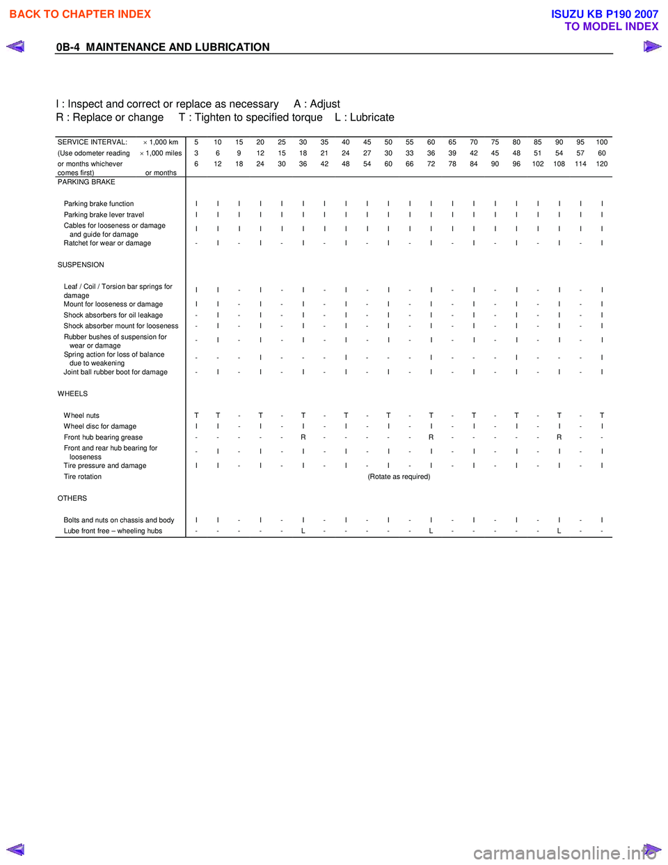
0B-4 MAINTENANCE AND LUBRICATION
I : Inspect and correct or replace as necessary A : Adjust
R : Replace or change T : Tighten to specified torque L : Lubricate
SERVICE INTERVAL: × 1,000 km 5 10 15 20 25 30 35 40 45 50 55 60 65 70 75 80 85 90 95 100(Use odometer reading × 1,000 miles 3 6 9 12 15 18 21 24 27 30 33 36 39 42 45 48 51 54 57 60or months whichever
comes first)
or months 6 12 18 24 30 36 42 48 54 60 66 72 78 84 90 96 102 108 114 120
PARKING BRAKE
Parking brake function I I I I I I I I I I I I I I I I I I I I Parking brake lever travel I I I I I I I I I I I I I I I I I I I I Cables for looseness or damage
and guide for damage I I I I I I I I I I I I I I I I I I I I
Ratchet for wear or damage - I - I - I - I - I - I - I - I - I - I
SUSPENSION Leaf / Coil / Torsion bar springs for
damage I I - I - I - I - I - I - I - I - I - I
Mount for looseness or damage I I - I - I - I - I - I - I - I - I - I Shock absorbers for oil leakage - I - I - I - I - I - I - I - I - I - I Shock absorber mount for looseness - I - I - I - I - I - I - I - I - I - I Rubber bushes of suspension for
wear or damage - I - I - I - I - I - I - I - I - I - I
Spring action for loss of balance
due to weakening - - - I - - - I - - - I - - - I - - - I
Joint ball rubber boot for damage - I - I - I - I - I - I - I - I - I - I
WHEELS W heel nuts T T - T - T - T - T - T - T - T - T - T W heel disc for damage I I - I - I - I - I - I - I - I - I - I Front hub bearing grease - - - - - R - - - - - R - - - - - R - - Front and rear hub bearing for
looseness - I - I - I - I - I - I - I - I - I - I
Tire pressure and damage I I - I - I - I - I - I - I - I - I - I Tire rotation
(Rotate as required) OTHERS Bolts and nuts on chassis and body I I - I - I - I - I - I - I - I - I - I Lube front free – wheeling hubs - - - - - L - - - - - L - - - - - L - -
BACK TO CHAPTER INDEX
TO MODEL INDEX
ISUZU KB P190 2007
Page 24 of 6020

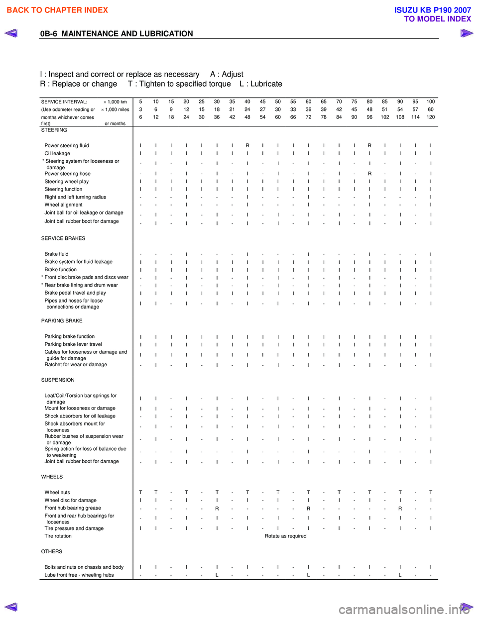
0B-6 MAINTENANCE AND LUBRICATION
I : Inspect and correct or replace as necessary A : Adjust
R : Replace or change T : Tighten to specified torque L : Lubricate
SERVICE INTERVAL: × 1,000 km 5 10 15 20 25 30 35 40 45 50 55 60 65 70 75 80 85 90 95 100
(Use odometer reading or × 1,000 miles 3 6 9 12 15 18 21 24 27 30 33 36 39 42 45 48 51 54 57 60
months whichever comes
first)
or months 6 12 18 24 30 36 42 48 54 60 66 72 78 84 90 96 102 108 114 120
STEERING Power steering fluid I I I I I I I R I I I I I I I R I I I I Oil leakage I I I I I I I I I I I I I I I I I I I I * Steering system for looseness or
damage - I - I - I - I - I - I - I - I - I - I
Power steering hose
- I - I - I - I - I - I - I - R - I - I Steering wheel play I I I I I I I I I I I I I I I I I I I I Steering function I I I I I I I I I I I I I I I I I I I I Right and left turning radius - - - I - - - I - - - I - - - I - - - I W heel alignment - - - I - - - I - - - I - - - I - - - I Joint ball for oil leakage or damage
- I - I - I - I - I - I - I - I - I - I
Joint ball rubber boot for damage - I - I - I - I - I - I - I - I - I - I
SERVICE BRAKES Brake fluid - - - I - - - I - - - I - - - I - - - I Brake system for fluid leakage I I I I I I I I I I I I I I I I I I I I Brake function I I I I I I I I I I I I I I I I I I I I * Front disc brake pads and discs wear - I - I - I - I - I - I - I - I - I - I * Rear brake lining and drum wear - I - I - I - I - I - I - I - I - I - I Brake pedal travel and play I I I I I I I I I I I I I I I I I I I I Pipes and hoses for loose
connections or damage I I - I - I - I - I - I - I - I - I - I
PARKING BRAKE Parking brake function I I I I I I I I I I I I I I I I I I I I Parking brake lever travel I I I I I I I I I I I I I I I I I I I I Cables for looseness or damage and
guide for damage I I I I I I I I I I I I I I I I I I I I
Ratchet for wear or damage
- I - I - I - I - I - I - I - I - I - I SUSPENSION Leaf/Coil/Torsion bar springs for
damage I I - I - I - I - I - I - I - I - I - I
Mount for looseness or damage
I I - I - I - I - I - I - I - I - I - I Shock absorbers for oil leakage - I - I - I - I - I - I - I - I - I - I Shock absorbers mount for
looseness - I - I - I - I - I - I - I - I - I - I
Rubber bushes of suspension wear
or damage - I - I - I - I - I - I - I - I - I - I
Spring action for loss of balance due
to weakening - - - I - - - I - - - I - - - I - - - I
Joint ball rubber boot for damage
- I - I - I - I - I - I - I - I - I - I WHEELS W heel nuts T T - T - T - T - T - T - T - T - T - T W heel disc for damage I I - I - I - I - I - I - I - I - I - I Front hub bearing grease
- - - - - R - - - - - R - - - - - R - - Front and rear hub bearings for
looseness - I - I - I - I - I - I - I - I - I - I
Tire pressure and damage I I - I - I - I - I - I - I - I - I - I Tire rotation
Rotate as required OTHERS Bolts and nuts on chassis and body I I - I - I - I - I - I - I - I - I - I Lube front free - wheeling hubs - - - - - L - - - - - L - - - - - L - -
BACK TO CHAPTER INDEX
TO MODEL INDEX
ISUZU KB P190 2007
Page 26 of 6020

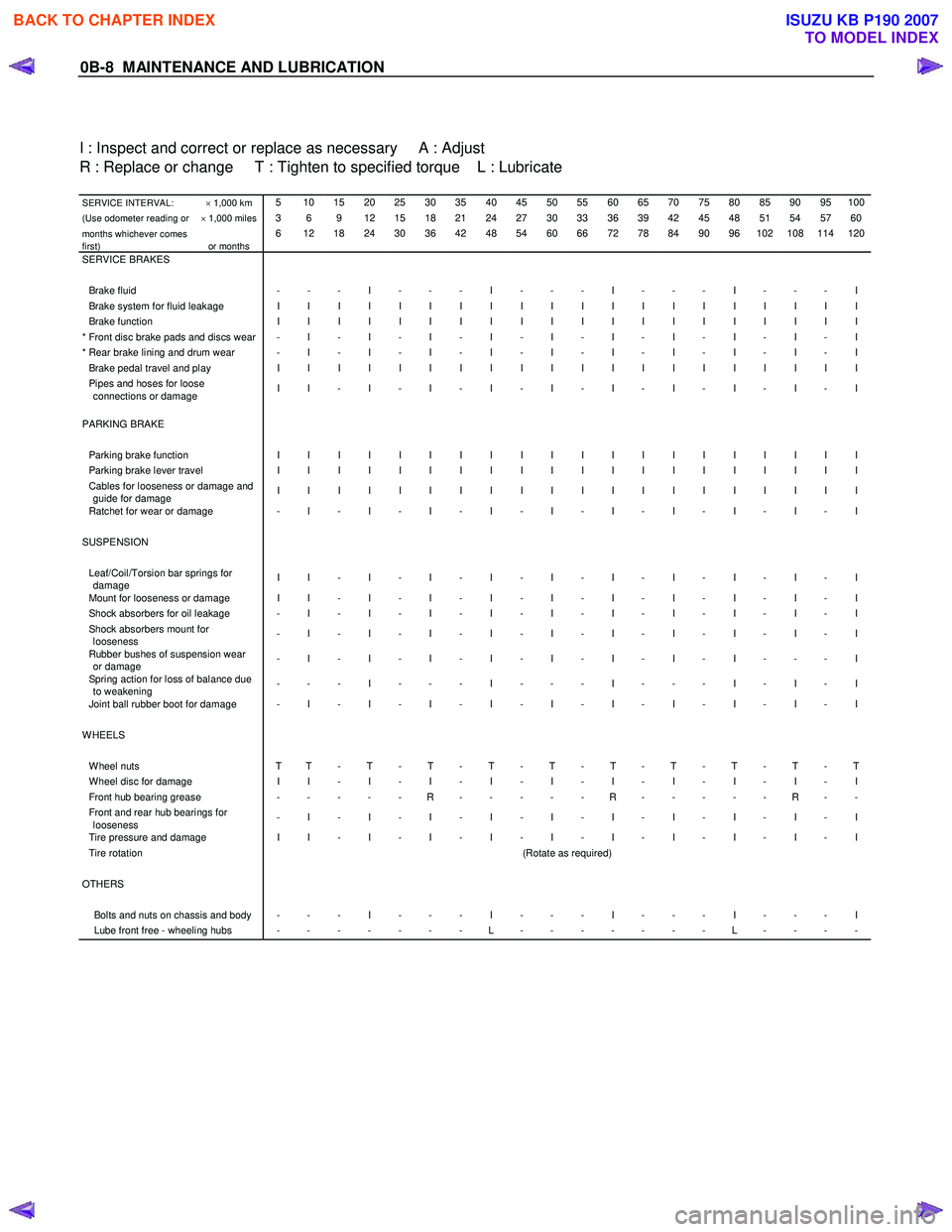
0B-8 MAINTENANCE AND LUBRICATION
I : Inspect and correct or replace as necessary A : Adjust
R : Replace or change T : Tighten to specified torque L : Lubricate
SERVICE INTERVAL: × 1,000 km 5 10 15 20 25 30 35 40 45 50 55 60 65 70 75 80 85 90 95 100
(Use odometer reading or × 1,000 miles 3 6 9 12 15 18 21 24 27 30 33 36 39 42 45 48 51 54 57 60
months whichever comes
first)
or months 6 12 18 24 30 36 42 48 54 60 66 72 78 84 90 96 102 108 114 120
SERVICE BRAKES Brake fluid - - - I - - - I - - - I - - - I - - - I Brake system for fluid leakage I I I I I I I I I I I I I I I I I I I I Brake function I I I I I I I I I I I I I I I I I I I I * Front disc brake pads and discs wear - I - I - I - I - I - I - I - I - I - I * Rear brake lining and drum wear - I - I - I - I - I - I - I - I - I - I Brake pedal travel and play I I I I I I I I I I I I I I I I I I I I Pipes and hoses for loose
connections or damage I I - I - I - I - I - I - I - I - I - I
PARKING BRAKE Parking brake function I I I I I I I I I I I I I I I I I I I I Parking brake lever travel I I I I I I I I I I I I I I I I I I I I Cables for looseness or damage and
guide for damage I I I I I I I I I I I I I I I I I I I I
Ratchet for wear or damage - I - I - I - I - I - I - I - I - I - I
SUSPENSION Leaf/Coil/Torsion bar springs for
damage I I - I - I - I - I - I - I - I - I - I
Mount for looseness or damage I I - I - I - I - I - I - I - I - I - I Shock absorbers for oil leakage - I - I - I - I - I - I - I - I - I - I Shock absorbers mount for
looseness - I - I - I - I - I - I - I - I - I - I
Rubber bushes of suspension wear
or damage - I - I - I - I - I - I - I - I - - - I
Spring action for loss of balance due
to weakening - - - I - - - I - - - I - - - I - I - I
Joint ball rubber boot for damage - I - I - I - I - I - I - I - I - I - I
WHEELS W heel nuts T T - T - T - T - T - T - T - T - T - T W heel disc for damage I I - I - I - I - I - I - I - I - I - I Front hub bearing grease - - - - - R - - - - - R - - - - - R - - Front and rear hub bearings for
looseness - I - I - I - I - I - I - I - I - I - I
Tire pressure and damage I I - I - I - I - I - I - I - I - I - I Tire rotation
(Rotate as required) OTHERS Bolts and nuts on chassis and body - - - I - - - I - - - I - - - I - - - I Lube front free - wheeling hubs - - - - - - - L - - - - - - - L - - - -
BACK TO CHAPTER INDEX
TO MODEL INDEX
ISUZU KB P190 2007
Page 390 of 6020

3D-6 REAR SUSPENSION
LEAF SPRING AND SHOCK ABSORBER
LEAF SPRING AND ASSOCIATED PARTS
460R300001
Legend
1. Parking Brake Cable Bracket
2. Nut and W asher
3. Nut and W asher
4. Shock Absorber
5. Nut
6. U Bolt and Seat
7. Lower Clamp
8. Nut
9. Shackle Plate
10. Shackle Pin
11. Rubber Bushing
12. Nut and Plain W asher
13. Spring Pin
14. Leaf Spring
15. Bump Rubber
BACK TO CHAPTER INDEX
TO MODEL INDEX
ISUZU KB P190 2007
Page 391 of 6020

REAR SUSPENSION 3D-7
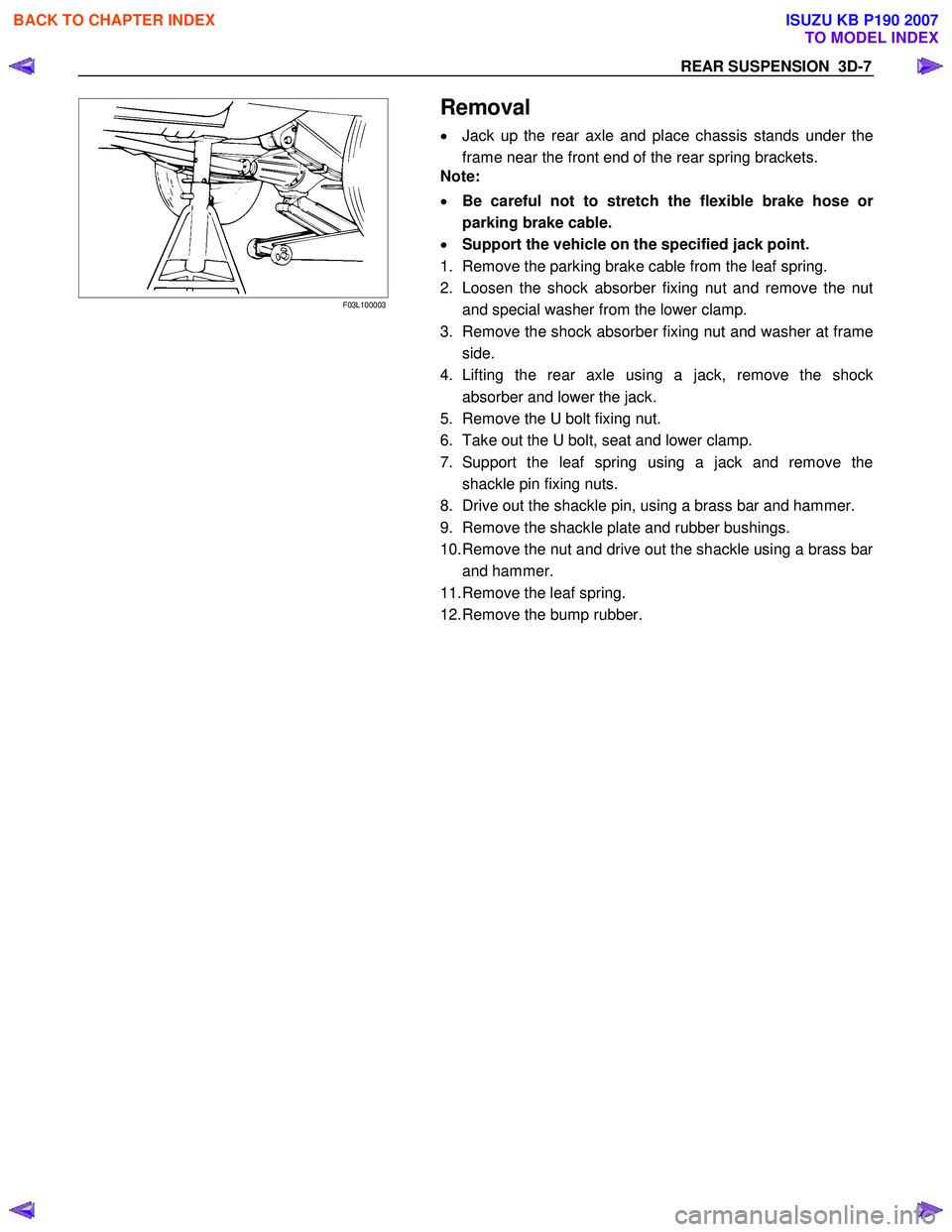
F03L100003
Removal
• Jack up the rear axle and place chassis stands under the
frame near the front end of the rear spring brackets.
Note:
• Be careful not to stretch the flexible brake hose o
r
parking brake cable.
• Support the vehicle on the specified jack point.
1. Remove the parking brake cable from the leaf spring.
2. Loosen the shock absorber fixing nut and remove the nut and special washer from the lower clamp.
3. Remove the shock absorber fixing nut and washer at frame
side.
4. Lifting the rear axle using a jack, remove the shock
absorber and lower the jack.
5. Remove the U bolt fixing nut.
6. Take out the U bolt, seat and lower clamp.
7. Support the leaf spring using a jack and remove the shackle pin fixing nuts.
8. Drive out the shackle pin, using a brass bar and hammer.
9. Remove the shackle plate and rubber bushings.
10. Remove the nut and drive out the shackle using a brass bar and hammer.
11. Remove the leaf spring.
12. Remove the bump rubber.
BACK TO CHAPTER INDEX
TO MODEL INDEX
ISUZU KB P190 2007
Page 394 of 6020

3D-10 REAR SUSPENSION
9. Install the parking brake cable on the leaf spring and
tighten the nut at its bracket.
Torque N ⋅m (kgf ⋅m/lb ⋅in)
7 (0.7/61)
BACK TO CHAPTER INDEX
TO MODEL INDEX
ISUZU KB P190 2007
Page 436 of 6020

4A-20 PROPELLER SHAFT
Front Propeller Shaft
Removal and Installation
RUW 54AMF000201
Legend
1. Bolt, Nut and W asher (Front Axle Side)
2. Front Propeller Shaft
3. Nut and W asher (Transfer Side)
401RS020
Removal
1. Jack up the vehicle and support it on the chassis stands.
2. Gear shift lever should be placed in neutral position and parking brake released.
3. Remove the exhaust and transfer protectors.
NOTE:
Apply alignment marks on the flange at the front propeller shaft
both front and rear side.
4. Remove bolt, nut and washer (Front axle side).
5. Remove bolt, nut and washer (Transfer side).
6. Remove front propeller shaft.
BACK TO CHAPTER INDEX
TO MODEL INDEX
ISUZU KB P190 2007
Page 455 of 6020

REAR AXLE 4B-11
305R30000
Legend
1. Tension Pin
2. Shoe Clamp Spring
3. Return Spring
4. Shoe Assembly with Parking Brake Lever
5. Shoe Assembly with Adjuster Lever
6. Spring
7. Parking Brake Cable
8. Adjuster
9. Parking Brake Lever
10. Adjuster Spring
11. Adjuster Lever
12. W heel Cylinder
13. Back plate
4. Remove tension pin and shoe clamp spring.
5. Remove return spring.
6. Remove shoe assembly with parking brake lever.
7. Remove shoe assembly with adjuster lever and spring.
8. Remove parking brake inner cable from parking
brake lever.
BACK TO CHAPTER INDEX
TO MODEL INDEX
ISUZU KB P190 2007
Page 456 of 6020

4B-12 REAR AXLE
9. Use offset box wrench to compress locking lugs
on the cable, then remove parking brake oute
r
cable from back plate.
311RS012
Legend
1. Offset Box W rench
10. Remove wheel cylinder.
11. Remove bearing holder fixing nuts.
12. Take out axle shaft assembly with back plate and
set it on a bench press as following illustration.
W hen axle shaft is extracted, since axle case oil
seal is damaged, replace the axle case oil seal.
13. Remove snap ring. Use snap ring pliers to
remove. Snap ring is prohibition of reuse.
14. Remove shim (If so equipped)
15. Grind the retainer surfaces using a grinder, then chisel them out with a chisel.
16. Position remover 5-8840-2831-0 on the bearing
holder with 4 nuts.
RTW 54BSH000801
BACK TO CHAPTER INDEX
TO MODEL INDEX
ISUZU KB P190 2007
Page 461 of 6020

REAR AXLE 4B-17
8. Certainly install new snap ring, use snap ring
pliers. W hen transform or damage, replace ne
w
one.
RTW 34BMH000101
Legend
1. Snap ring
2. Crevice
3. Retainer (with ABS)
Retainer (without ABS)
9. Insert a shim of sufficient thickness between
snap ring and end of retainer.
Standard 0 − 0.2 mm (0 − 0.008 in)
Crevice is measured using thickness gauge, and
when crevice exceeds 0.2 mm (0.008 in), it
adjusts so that is may become 0.2 mm (0.008 in)
or less using shim.
Shim Pats No. Thickness
1 9-41519110- ∗ 0.18 mm (0.0071 in)
2 8-97130387- ∗ 0.50 mm (0.0197 in)
Crevice No. of shim Total
mm (in)
1 2 mm (in)
1.0(0.0394) 2 1.00(0.0394)
0.9(0.0354) 2 1 0.86(0.0339)
0.8(0.0315) 1 1 0.68(0.0268)
0.7(0.0276) 1 1 0.68(0.0268)
0.6(0.0236) 1 0.50(0.0197)
0.5(0.0197) 1 0.50(0.0197)
0.4(0.0157) 2 0.36(0.0142)
0.3(0.0118) 1 0.18(0.0071)
0.2(0.0079) 1 0.18(0.0071)
10. Install axle shaft assembly in rear axle case
assembly.
a. Clean the mating surface of axle case and bearing holder.
b. Apply Three Bond 1215 (TB1215) o
r
equivalent on the surface of axle case
assembly.
Note:
When inserting an axle shaft, it inserts so that an
oil seal may not be damaged.
11. Install and tighten bearing holder fixing nut to the specified torque.
Torque : 84 N ⋅m (8.6 kgf ⋅m/62 lb ⋅ft)
12. Install wheel cylinder and tighten the bolt to the specified torque.
Torque : 9 N ⋅m (0.9 kgf ⋅m/78 lb ⋅in)
13. Install parking brake outer cable in back plate and inner cable in parking brake lever.
BACK TO CHAPTER INDEX
TO MODEL INDEX
ISUZU KB P190 2007