map ISUZU KB P190 2007 Workshop Repair Manual
[x] Cancel search | Manufacturer: ISUZU, Model Year: 2007, Model line: KB P190, Model: ISUZU KB P190 2007Pages: 6020, PDF Size: 70.23 MB
Page 1072 of 6020
6E-38 Engine Control System (4JH1)
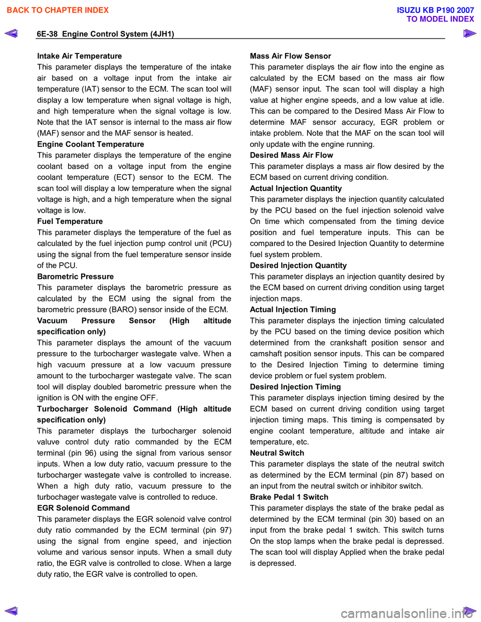
Intake Air Temperature
This parameter displays the temperature of the intake
air based on a voltage input from the intake ai
r
temperature (IAT) sensor to the ECM. The scan tool will
display a low temperature when signal voltage is high,
and high temperature when the signal voltage is low.
Note that the IAT sensor is internal to the mass air flo
w
(MAF) sensor and the MAF sensor is heated.
Engine Coolant Temperature
This parameter displays the temperature of the engine
coolant based on a voltage input from the engine
coolant temperature (ECT) sensor to the ECM. The
scan tool will display a low temperature when the signal
voltage is high, and a high temperature when the signal
voltage is low.
Fuel Temperature
This parameter displays the temperature of the fuel as
calculated by the fuel injection pump control unit (PCU)
using the signal from the fuel temperature sensor inside
of the PCU.
Barometric Pressure
This parameter displays the barometric pressure as
calculated by the ECM using the signal from the
barometric pressure (BARO) sensor inside of the ECM.
Vacuum Pressure Sensor (High altitude
specification only)
This parameter displays the amount of the vacuum
pressure to the turbocharger wastegate valve. W hen a
high vacuum pressure at a low vacuum pressure
amount to the turbocharger wastegate valve. The scan
tool will display doubled barometric pressure when the
ignition is ON with the engine OFF.
Turbocharger Solenoid Command (High altitude
specification only)
This parameter displays the turbocharger solenoid
valuve control duty ratio commanded by the ECM
terminal (pin 96) using the signal from various senso
r
inputs. W hen a low duty ratio, vacuum pressure to the
turbocharger wastegate valve is controlled to increase.
W hen a high duty ratio, vacuum pressure to the
turbochager wastegate valve is controlled to reduce.
EGR Solenoid Command
This parameter displays the EGR solenoid valve control
duty ratio commanded by the ECM terminal (pin 97)
using the signal from engine speed, and injection
volume and various sensor inputs. W hen a small dut
y
ratio, the EGR valve is controlled to close. W hen a large
duty ratio, the EGR valve is controlled to open.
Mass Air Flow Sensor
This parameter displays the air flow into the engine as
calculated by the ECM based on the mass air flo
w
(MAF) sensor input. The scan tool will display a high
value at higher engine speeds, and a low value at idle.
This can be compared to the Desired Mass Air Flow to
determine MAF sensor accuracy, EGR problem o
r
intake problem. Note that the MAF on the scan tool will
only update with the engine running.
Desired Mass Air Flow
This parameter displays a mass air flow desired by the
ECM based on current driving condition.
Actual Injection Quantity
This parameter displays the injection quantity calculated
by the PCU based on the fuel injection solenoid valve
On time which compensated from the timing device
position and fuel temperature inputs. This can be
compared to the Desired Injection Quantity to determine
fuel system problem.
Desired Injection Quantity
This parameter displays an injection quantity desired b
y
the ECM based on current driving condition using target
injection maps.
Actual Injection Timing
This parameter displays the injection timing calculated
by the PCU based on the timing device position which
determined from the crankshaft position sensor and
camshaft position sensor inputs. This can be compared
to the Desired Injection Timing to determine timing
device problem or fuel system problem.
Desired Injection Timing
This parameter displays injection timing desired by the
ECM based on current driving condition using target
injection timing maps. This timing is compensated b
y
engine coolant temperature, altitude and intake ai
r
temperature, etc.
Neutral Switch
This parameter displays the state of the neutral switch
as determined by the ECM terminal (pin 87) based on
an input from the neutral switch or inhibitor switch.
Brake Pedal 1 Switch
This parameter displays the state of the brake pedal as
determined by the ECM terminal (pin 30) based on an
input from the brake pedal 1 switch. This switch turns
On the stop lamps when the brake pedal is depressed.
The scan tool will display Applied when the brake pedal
is depressed.
BACK TO CHAPTER INDEX
TO MODEL INDEX
ISUZU KB P190 2007
Page 1088 of 6020

6E-54 Engine Control System (4JH1)
DTC
(Symptom Code) Flash
Code MIL
Status DTC Name on
scan tool Condition for
Running the DTC Condition for
Setting the DTC Possible Cause
P0243
(8) 64 ON Turbocharger
W aste gate
Solenoid Boost
Solenoid Circuit
High Voltage •
The ignition switch
is ON. •
The ECM detects
that the high
voltage condition on
the turbocharger
solenoid valve
control circuit for
longer than 3
seconds when the
solenoid valve is
commanded ON.
•
Turbocharger solenoid valve
control circuit is short to battery
or ignition voltage circuit.
• Faulty turbocharger solenoid
valve.
• Faulty ECM.
P0251 (6) 53 ON Injection Pump
Fuel Metering
Control •
The fuel injection
pump CMP sensor
signal is generated.
• The CAN
communication
between the ECM
and PCU is normal.
•
The PCU detects
that the fuel
injection solenoid
valve is operated
when the desired
fuel injection
quantity is
commanded 0
mg/strk.
•
Faulty fuel injection pump.
• Faulty PCU.
P0251 (7) 53 ON Injection Pump
Fuel Metering
Control •
The fuel injection
pump CMP sensor
signal is generated.
• The CKP sensor
signal is generated.
• The engine speed
is higher than 500
RPM.
•
The PCU detects
that the doubled
fuel injection pump
speed is lower than
engine speed by
690 RPM for longer
than 0.2 seconds.
•
Faulty CKP sensor signal.
• Faulty fuel injection pump CMP
sensor signal.
• Electrical interference.
• Magnetic interference.
• Faulty PCU.
P0251 (9) 53 ON Injection Pump
Fuel Metering
Control •
The ignition switch
is ON. •
The PCU detects
internal fuel
injection pump
control maps are
not programmed
during self-test.
•
Faulty PCU.
P0251 (A) 53 ON Injection Pump
Fuel Metering
Control •
The ignition switch
is ON. •
The PCU detects
internal EEPROM
or A/D converter is
failed during self-
test.
•
Faulty PCU.
P0251 (B) 53 ON Injection Pump
Fuel Metering
Control •
The ignition switch
is ON. •
The PCU detects
that the fuel
injection solenoid
valve drive circuit is
failed during self-
test.
•
Faulty fuel injection pump.
• Faulty PCU.
P0251 (D) 53 ON Injection Pump
Fuel Metering
Control •
The ignition switch
is ON. •
The PCU detects
that the fuel
injection solenoid
valve drive circuit
voltage level is
abnormal during
self-test.
•
Faulty fuel injection pump.
• Faulty PCU.
BACK TO CHAPTER INDEX
TO MODEL INDEX
ISUZU KB P190 2007
Page 1130 of 6020

6E-96 Engine Control System (4JH1)
DTC P0215 (Symptom Code A) (Flash Code 52)
Circuit Description
The engine control module (ECM) calculates the
desired fuel injection quantity and timing using data sent
from various sensors. These desired data are sent to
the fuel injection pump control unit (PCU) via a
controller area network (CAN) communication bus. The
PCU also receives signals from the internal inputs:
pump camshaft position (CMP) sensor that is located
inside the fuel injection pump to determine the cam ring
rotation angle and the fuel injection pump speed. The
fuel temperature (FT) sensor is internal the PCU. These
values are used to compare the desired values sent
from the ECM then PCU determines the injection time
r
piston position and fuel injection quantity, and actuates
timing control valve (TCV) & fuel injection solenoid
valve based on control maps in the PCU.
The fuel injection solenoid valve is installed to the fuel
injection pump rear side. The fuel injection event is
determined by this solenoid ON/OFF command. The
fuel injection solenoid valve cuts the fuel when the
engine shutoff (ESO) solenoid valve is commanded
shutoff from the PCU. (The fuel injection solenoid valve
and engine shutoff (ESO) solenoid valve is same part. It
calls ESO solenoid valve when fuel is shutoff.) W hen
the ignition switch is turned OFF or commanded from
fail-safe action, the ESO solenoid valve is commanded
shutoff to stop the engine running. If the ECM detects
that the engine is continuously run after the ignition
switch is OFF, this DTC will set.
Condition for Running the DTC
• The ignition switch is OFF.
• The engine speed is lower than 1500 RPM.
• The vehicle speed is lower than 1.5 km/h (1 MPH).
Condition for Setting the DTC
•
After the condition for running this DTC for 2
seconds, the engine speed is higher than 200
RPM when the ESO solenoid valve is commanded
shutoff from the CPU. This indicates the PCU
reacts to the command from the ECM but ESO
solenoid valve does not react to the command
from the PCU and fuel cannot shutoff.
Action Taken When the DTC Sets
• The ECM illuminates the malfunction indicato
r
lamp (MIL) at next ignition cycle.
• The ECM cuts fuel injection.
Condition for Clearing the MIL/DTC
• The ECM turns OFF the MIL when the diagnostic
runs and does not fail.
• A history DTC clears after 40 consecutive driving
cycles without a fault. Or clear with the scan tool.
Diagnostic Aids
• If an intermittent condition is suspected, refer to
Intermittent Conditions in this section.
Notice:
• Fuel injection solenoid valve is internal to the fuel
injection pump assembly.
• PCU is part of the fuel injection pump assembly.
DTC P0215 (Symptom Code A) (Flash Code 52)
Step Action Value(s) Yes No
1 Did you perform the Diagnostic System Check-
Engine Controls?
Go to Step 2 Go to Diagnostic
System Check-
Engine Controls
2 1. Install the scan tool. 2. Turn OFF the ignition for 30 seconds.
3. Start the engine and let idle for 30 seconds.
4. Monitor the Diagnostic Trouble Code (DTC) Information with the scan tool.
5. Turn OFF the engine.
Does the DTC fail this ignition before the engine
control module (ECM) turned OFF?
Go to Step 3 Go to Step 4
3 Important: The fuel injection pump must be timed to
the engine.
Replace the fuel injection pump. Refer to Fuel
Injection Pump Replacement in engine mechanical
section.
Did you complete the replacement?
Go to Step 4
BACK TO CHAPTER INDEX
TO MODEL INDEX
ISUZU KB P190 2007
Page 1132 of 6020

6E-98 Engine Control System (4JH1)
DTC P0215 (Symptom Code B) (Flash Code 52)
Circuit Description
The engine control module (ECM) calculates the
desired fuel injection quantity and timing using data sent
from various sensors. These desired data are sent to
the fuel injection pump control unit (PCU) via a
controller area network (CAN) communication bus. The
PCU also receives signals from the internal inputs:
pump camshaft position (CMP) sensor that is located
inside the fuel injection pump to determine the cam ring
rotation angle and the fuel injection pump speed. The
fuel temperature (FT) sensor is internal the PCU. These
values are used to compare the desired values sent
from the ECM then PCU determines the injection time
r
piston position and fuel injection quantity, and actuates
timing control valve (TCV) & fuel injection solenoid
valve based on control maps in the PCU.
The fuel injection solenoid valve is installed to the fuel
injection pump rear side. The fuel injection event is
determined by this solenoid ON/OFF command. The
fuel injection solenoid valve cuts the fuel when the
engine shutoff (ESO) solenoid valve is commanded
shutoff from the PCU. (The fuel injection solenoid valve
and engine shutoff (ESO) solenoid valve is same part. It
calls ESO solenoid valve when fuel is shutoff.) W hen
the ignition switch is turned OFF or commanded from
fail-safe action, the ESO solenoid valve is commanded
shutoff to stop the engine running. If the PCU detects
that the ESO solenoid valve control circuit voltage level
from the ECM to PCU is high, this DTC will set.
Condition for Running the DTC
• The ignition switch is ON.
Condition for Setting the DTC
• The PCU detects high voltage condition on the
ESO solenoid valve control circuit for longer than 1
second when the ECM does not command shutoff.
Action Taken When the DTC Sets
• The ECM illuminates the malfunction indicato
r
lamp (MIL) when the diagnostic runs and fails.
Condition for Clearing the MIL/DTC
• The ECM turns OFF the MIL when the diagnostic
runs and does not fail.
• A history DTC clears after 40 consecutive driving
cycles without a fault. Or clear with the scan tool.
Diagnostic Aids
• If an intermittent condition is suspected, refer to
Intermittent Conditions in this section.
Notice:
• Fuel injection solenoid valve is internal to the fuel
injection pump assembly.
• PCU is part of the fuel injection pump assembly.
• If this DTC is present, engine will not start.
DTC P0215 (Symptom Code B) (Flash Code 52)
Schematic Reference: Engine Controls Schematics
Connector End View Reference: Engine Controls
Connector End Views or Engine Control Module (ECM)
Connector End Views
Step Action Value(s) Yes No
1 Did you perform the Diagnostic System Check-
Engine Controls?
Go to Step 2 Go to Diagnostic
System Check-
Engine Controls
2 1. Install the scan tool. 2. Turn OFF the ignition for 30 seconds.
3. Start the engine. If the engine does not start, crank over the engine.
4. Monitor the Diagnostic Trouble Code (DTC) Information with the scan tool.
Does the DTC fail this ignition?
Go to Step 3 Go to Diagnostic
Aids
3 1. Turn OFF the ignition. 2. Disconnect the fuel injection pump control unit (PCU) harness connector.
3. Connect a test lamp between the engine shutoff (ESO) solenoid valve control signal circuit (pin 5
of E-6 connector) and a known good ground.
4. Turn ON the ignition, with the engine OFF.
Does the test lamp illuminate?
Go to Step 5 Go to Step 4
BACK TO CHAPTER INDEX
TO MODEL INDEX
ISUZU KB P190 2007
Page 1134 of 6020

6E-100 Engine Control System (4JH1)
DTC P0215 (Symptom Code C) (Flash Code 52)
Circuit Description
The engine control module (ECM) calculates the
desired fuel injection quantity and timing using data sent
from various sensors. These desired data are sent to
the fuel injection pump control unit (PCU) via a
controller area network (CAN) communication bus. The
PCU also receives signals from the internal inputs:
pump camshaft position (CMP) sensor that is located
inside the fuel injection pump to determine the cam ring
rotation angle and the fuel injection pump speed. The
fuel temperature (FT) sensor is internal the PCU. These
values are used to compare the desired values sent
from the ECM then PCU determines the injection time
r
piston position and fuel injection quantity, and actuates
timing control valve (TCV) & fuel injection solenoid
valve based on control maps in the PCU.
The fuel injection solenoid valve is installed to the fuel
injection pump rear side. The fuel injection event is
determined by this solenoid ON/OFF command. The
fuel injection solenoid valve cuts the fuel when the
engine shutoff (ESO) solenoid valve is commanded
shutoff from the PCU. (The fuel injection solenoid valve
and engine shutoff (ESO) solenoid valve is same part. It
calls ESO solenoid valve when fuel is shutoff.) W hen
the ignition switch is turned OFF or commanded from
fail-safe action, the ESO solenoid valve is commanded
shutoff to stop the engine running. If the ECM detects
that the engine is continuously run after the ignition
switch is OFF, this DTC will set.
Condition for Running the DTC
• The ignition switch is OFF.
• The engine speed is lower than 1500 RPM.
• The vehicle speed is lower than 1.5 km/h (1 MPH).
Condition for Setting the DTC
• The engine speed is higher than 200 RPM within 2
seconds after the condition for running the DTC
are met. This indicates the PCU does not react to
the command from the ECM and fuel cannot
shutoff.
Action Taken When the DTC Sets
• The ECM illuminates the malfunction indicato
r
lamp (MIL) when the diagnostic runs and fails.
• The ECM cuts fuel injection.
Condition for Clearing the MIL/DTC
• The ECM turns OFF the MIL when the diagnostic
runs and does not fail.
• A history DTC clears after 40 consecutive driving
cycles without a fault. Or clear with the scan tool.
Diagnostic Aids
• If an intermittent condition is suspected, refer to
Intermittent Conditions in this section.
Notice:
• Fuel injection solenoid valve is internal to the fuel
injection pump assembly.
• PCU is part of the fuel injection pump assembly.
DTC P0215 (Symptom Code C) (Flash Code 52)
Schematic Reference: Engine Controls Schematics
Connector End View Reference: Engine Controls
Connector End Views or Engine Control Module (ECM)
Connector End Views
Step Action Value(s) Yes No
1 Did you perform the Diagnostic System Check-
Engine Controls?
Go to Step 2 Go to Diagnostic
System Check-
Engine Controls
2 1. Install the scan tool. 2. Turn OFF the ignition for 30 seconds.
3. Start the engine and let idle for 30 seconds.
4. Monitor the Diagnostic Trouble Code (DTC) Information with the scan tool.
5. Turn OFF the engine.
Does the DTC fail this ignition before the engine
control module (ECM) turns OFF?
Go to Step 3 Go to Diagnostic
Aids
3 1. Turn OFF the ignition. 2. Disconnect the fuel injection pump control unit (PCU) harness connector.
3. Connect a test lamp between the engine shutoff (ESO) solenoid valve control signal circuit (pin 5
of E-6 connector) and battery voltage.
4. Turn ON the ignition, with the engine OFF.
Does the test lamp illuminate?
Go to Step 5 Go to Step 4
BACK TO CHAPTER INDEX
TO MODEL INDEX
ISUZU KB P190 2007
Page 1136 of 6020

6E-102 Engine Control System (4JH1)
DTC P0215 (Symptom Code D) (Flash Code 52)
Circuit Description
The engine control module (ECM) calculates the
desired fuel injection quantity and timing using data sent
from various sensors. These desired data are sent to
the fuel injection pump control unit (PCU) via a
controller area network (CAN) communication bus. The
PCU also receives signals from the internal inputs:
pump camshaft position (CMP) sensor that is located
inside the fuel injection pump to determine the cam ring
rotation angle and the fuel injection pump speed. The
fuel temperature (FT) sensor is internal the PCU. These
values are used to compare the desired values sent
from the ECM then PCU determines the injection time
r
piston position and fuel injection quantity, and actuates
timing control valve (TCV) & fuel injection solenoid
valve based on control maps in the PCU.
The ECM monitors CAN operational status by expecting
a constant flow of messages from the PCU. If the ECM
detects that the internal CAN controller does not Bus
OFF when the ignition switch is OFF, this DTC will set.
Condition for Running the DTC
• The ignition switch is OFF.
Condition for Setting the DTC
• The ECM detects internal CAN controller does not
Bus OFF mode.
Action Taken When the DTC Sets
• The ECM illuminates the malfunction indicato
r
lamp (MIL) when the diagnostic runs and fails.
Condition for Clearing the MIL/DTC
• The ECM turns OFF the MIL when the diagnostic
runs and does not fail.
• A history DTC clears after 40 consecutive driving
cycles without a fault. Or clear with the scan tool.
Diagnostic Aids
• If an intermittent condition is suspected, refer to
Intermittent Conditions in this section.
Notice:
• CAN controller is internal to the ECM.
DTC P0215 (Symptom Code D) (Flash Code 52)
Step Action Value(s) Yes No
1 Did you perform the Diagnostic System Check-
Engine Controls?
Go to Step 2 Go to Diagnostic
System Check-
Engine Controls
2 1. Install the scan tool. 2. Turn OFF the ignition for 30 seconds.
3. Start the engine and let idle for 30 seconds.
4. Monitor the Diagnostic Trouble Code (DTC) Information with the scan tool.
5. Turn OFF the engine.
Does the DTC fail this ignition before the engine
control module (ECM) turns OFF?
Go to Step 3 Go to Step 4
3 Important: Replacement ECM must be
programmed.
Replace the ECM. Refer to Engine Control Module
(ECM) Replacement in this section.
Did you complete the replacement?
Go to Step 4
4 1. Clear the DTCs with the scan tool.
2. Turn OFF the ignition for 30 seconds.
3. Start the engine and let idle for 30 seconds.
4. Monitor the DTC Information with the scan tool.
5. Turn OFF the engine.
Does the DTC fail this ignition before the ECM turns
OFF?
Go to Step 3 Go to Step 5
5 Observe the DTC Information with the scan tool. Are there any DTCs that you have not diagnosed? Go to Diagnostic
Trouble Code (DTC) List System OK
BACK TO CHAPTER INDEX
TO MODEL INDEX
ISUZU KB P190 2007
Page 1137 of 6020
Engine Control System (4JH1) 6E-103
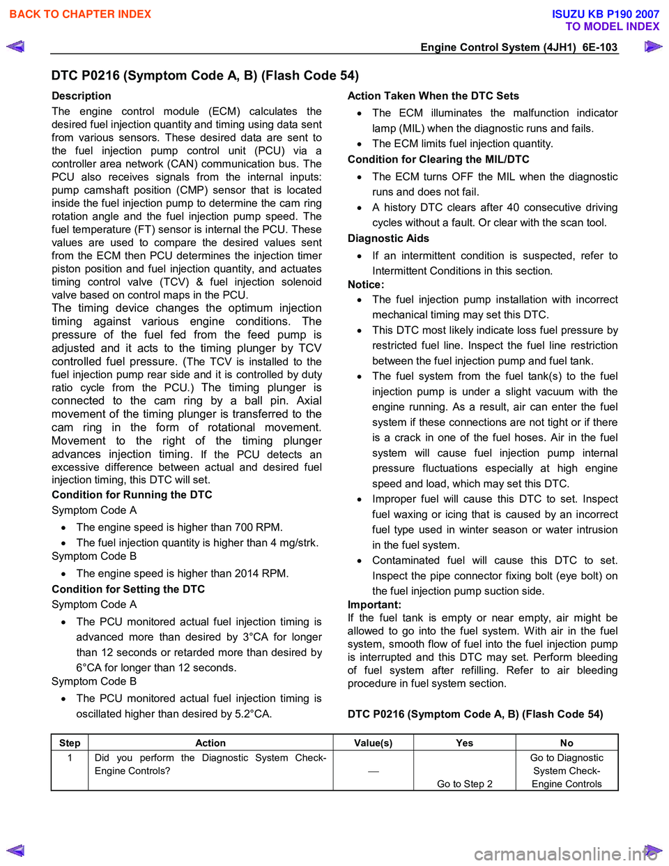
DTC P0216 (Symptom Code A, B) (Flash Code 54)
Description
The engine control module (ECM) calculates the
desired fuel injection quantity and timing using data sent
from various sensors. These desired data are sent to
the fuel injection pump control unit (PCU) via a
controller area network (CAN) communication bus. The
PCU also receives signals from the internal inputs:
pump camshaft position (CMP) sensor that is located
inside the fuel injection pump to determine the cam ring
rotation angle and the fuel injection pump speed. The
fuel temperature (FT) sensor is internal the PCU. These
values are used to compare the desired values sent
from the ECM then PCU determines the injection time
r
piston position and fuel injection quantity, and actuates
timing control valve (TCV) & fuel injection solenoid
valve based on control maps in the PCU.
The timing device changes the optimum injection
timing against various engine conditions. The
pressure of the fuel fed from the feed pump is
adjusted and it acts to the timing plunger by TCV
controlled fuel pressure. (
The TCV is installed to the
fuel injection pump rear side and it is controlled by dut
y
ratio cycle from the PCU.) The timing plunger is
connected to the cam ring by a ball pin. Axial
movement of the timing plunger is transferred to the
cam ring in the form of rotational movement.
Movement to the right of the timing plunge
r
advances injection timing.
If the PCU detects an
excessive difference between actual and desired fuel
injection timing, this DTC will set.
Condition for Running the DTC
Symptom Code A
• The engine speed is higher than 700 RPM.
• The fuel injection quantity is higher than 4 mg/strk.
Symptom Code B
• The engine speed is higher than 2014 RPM.
Condition for Setting the DTC
Symptom Code A
• The PCU monitored actual fuel injection timing is
advanced more than desired by 3°CA for longe
r
than 12 seconds or retarded more than desired by
6°CA for longer than 12 seconds.
Symptom Code B
• The PCU monitored actual fuel injection timing is
oscillated higher than desired by 5.2°CA.
Action Taken When the DTC Sets
• The ECM illuminates the malfunction indicato
r
lamp (MIL) when the diagnostic runs and fails.
• The ECM limits fuel injection quantity.
Condition for Clearing the MIL/DTC
• The ECM turns OFF the MIL when the diagnostic
runs and does not fail.
• A history DTC clears after 40 consecutive driving
cycles without a fault. Or clear with the scan tool.
Diagnostic Aids
• If an intermittent condition is suspected, refer to
Intermittent Conditions in this section.
Notice:
• The fuel injection pump installation with incorrect
mechanical timing may set this DTC.
• This DTC most likely indicate loss fuel pressure by
restricted fuel line. Inspect the fuel line restriction
between the fuel injection pump and fuel tank.
• The fuel system from the fuel tank(s) to the fuel
injection pump is under a slight vacuum with the
engine running. As a result, air can enter the fuel
system if these connections are not tight or if there
is a crack in one of the fuel hoses. Air in the fuel
system will cause fuel injection pump internal
pressure fluctuations especially at high engine
speed and load, which may set this DTC.
• Improper fuel will cause this DTC to set. Inspect
fuel waxing or icing that is caused by an incorrect
fuel type used in winter season or water intrusion
in the fuel system.
• Contaminated fuel will cause this DTC to set.
Inspect the pipe connector fixing bolt (eye bolt) on
the fuel injection pump suction side.
Important:
If the fuel tank is empty or near empty, air might be
allowed to go into the fuel system. W ith air in the fuel
system, smooth flow of fuel into the fuel injection pump
is interrupted and this DTC may set. Perform bleeding
of fuel system after refilling. Refer to air bleeding
procedure in fuel system section.
DTC P0216 (Symptom Code A, B) (Flash Code 54)
Step Action Value(s) Yes No
1 Did you perform the Diagnostic System Check-
Engine Controls?
Go to Step 2 Go to Diagnostic
System Check-
Engine Controls
BACK TO CHAPTER INDEX
TO MODEL INDEX
ISUZU KB P190 2007
Page 1157 of 6020

Engine Control System (4JH1) 6E-123
DTC P0251 (Symptom Code 6) (Flash Code 53)
Circuit Description
The engine control module (ECM) calculates the
desired fuel injection quantity and timing using data sent
from various sensors. These desired data are sent to
the fuel injection pump control unit (PCU) via a
controller area network (CAN) communication bus. The
PCU also receives signals from the internal inputs:
pump camshaft position (CMP) sensor that is located
inside the fuel injection pump to determine the cam ring
rotation angle and the fuel injection pump speed. The
fuel temperature (FT) sensor is internal the PCU. These
values are used to compare the desired values sent
from the ECM then PCU determines the injection time
r
piston position and fuel injection quantity, and actuates
timing control valve (TCV) & fuel injection solenoid
valve based on control maps in the PCU.
The fuel injection solenoid valve is installed to the fuel
injection pump rear side. The fuel injection event is
determined by this solenoid ON/OFF command. The
fuel injection solenoid valve cuts the fuel when the
engine shutoff (ESO) solenoid valve is commanded
shutoff from the PCU. (The fuel injection solenoid valve
and engine shutoff (ESO) solenoid valve is same part. It
calls ESO solenoid valve when fuel is shut off.) W hen
the ignition switch is turned OFF or commanded from
fail-safe action, the ESO solenoid valve is commanded
shutoff to stop the engine running. If the PCU detects
that the fuel injection solenoid valve is operated when
the desired injection quantity from the ECM is 0 mg/strk,
this DTC will set.
Condition for Running the DTC
• The fuel injection pump CMP sensor signal is
generated.
• The CAN communication between the ECM and
PCU is normal.
Condition for Setting the DTC
• The PCU detects that the fuel injection solenoid
valve is operated when the desired fuel injection
quantity is commanded 0 mg/strk.
Action Taken When the DTC Sets
• The ECM illuminates the malfunction indicator
lamp (MIL) when the diagnostic runs and fails.
• The ECM cuts fuel injection.
Condition for Clearing the MIL/DTC
• The ECM turns OFF the MIL when the diagnostic
runs and does not fail.
• A history DTC clears after 40 consecutive driving
cycles without a fault. Or clear with the scan tool.
Diagnostic Aids
• If an intermittent condition is suspected, refer to
Intermittent Conditions in this section.
Notice:
• Fuel injection solenoid valve is internal to the fuel
injection pump assembly.
• PCU is part of the fuel injection pump assembly.
DTC P0251 (Symptom Code 6) (Flash Code 53)
Step Action Value(s) Yes No
1 Did you perform the Diagnostic System Check-
Engine Controls?
Go to Step 2 Go to Diagnostic
System Check-
Engine Controls
2 1. Install the scan tool. 2. Turn OFF the ignition for 30 seconds.
3. Start the engine and let idle for 30 seconds.
4. Accelerate the engine between idle and W .O.T. (accelerator pedal full travel) many times while
observing the Diagnostic Trouble Code (DTC)
Information with the scan tool.
Does the DTC fail this ignition?
Go to Step 3 Go to Step 4
3 Important: The fuel injection pump must be timed to
the engine.
Replace the fuel injection pump. Refer to Fuel
Injection Pump Replacement in engine mechanical
section.
Did you complete the replacement?
Go to Step 4
BACK TO CHAPTER INDEX
TO MODEL INDEX
ISUZU KB P190 2007
Page 1159 of 6020

Engine Control System (4JH1) 6E-125
DTC P0251 (Symptom Code 7) (Flash Code 53)
Circuit Description
The engine control module (ECM) calculates the
desired fuel injection quantity and timing using data sent
from various sensors. These desired data are sent to
the fuel injection pump control unit (PCU) via a
controller area network (CAN) communication bus. The
PCU also receives signals from the internal inputs:
pump camshaft position (CMP) sensor that is located
inside the fuel injection pump to determine the cam ring
rotation angle and the fuel injection pump speed. The
fuel temperature (FT) sensor is internal the PCU. These
values are used to compare the desired values sent
from the ECM then PCU determines the injection time
r
piston position and fuel injection quantity, and actuates
timing control valve (TCV) & fuel injection solenoid
valve based on control maps in the PCU. The PCU also
compares the engine speed signal sent from the ECM
and the fuel injection pump speed. If the PCU detects
that the doubled fuel injection pump speed is
excessively lower than engine speed, this DTC will set.
Condition for Running the DTC
• The fuel injection pump CMP sensor signal is
generated.
• The crankshaft position (CKP) sensor signal is
generated.
• The engine speed is higher than 500 RPM.
Condition for Setting the DTC
• The PCU detects that the doubled fuel injection
pump speed is lower than engine speed by 690
RPM for longer than 0.2 seconds.
Action Taken When the DTC Sets
• The ECM illuminates the malfunction indicato
r
lamp (MIL) when the diagnostic runs and fails.
• The ECM cuts fuel injection.
Condition for Clearing the MIL/DTC
• The ECM turns OFF the MIL when the diagnostic
runs and does not fail.
• A history DTC clears after 40 consecutive driving
cycles without a fault. Or clear with the scan tool.
Diagnostic Aids
• Electrical or magnetic interference may affect
intermittent condition.
• If an intermittent condition is suspected, refer to
Intermittent Conditions in this section.
Notice:
• Fuel injection pump CMP sensor is internal to the
fuel injection pump assembly.
• PCU is part of the fuel injection pump assembly.
DTC P0251 (Symptom Code 7) (Flash Code 53)
Schematic Reference: Engine Controls Schematics
Connector End View Reference: Engine Controls
Connector End Views or Engine Control Module (ECM)
Connector End Views
Step Action Value(s) Yes No
1 Did you perform the Diagnostic System Check-
Engine Controls?
Go to Step 2 Go to Diagnostic
System Check-
Engine Controls
2 1. Install the scan tool. 2. Turn OFF the ignition for 30 seconds.
3. Start the engine. If the engine does not start, crank over the engine.
4. Monitor the Diagnostic Trouble Code (DTC) Information with the scan tool.
Is DTC P0335 (Symptom Code B, D or E), P1335
(Symptom Code A) or P1345 (Symptom Code A)
set?
Go to Applicable DTC Go to Step 3
3 1. Start the engine. 2. Monitor the DTC Information with the scan tool.
3. Accelerate the engine between idle and W .O.T. (accelerator pedal full travel) many times.
Does the DTC fail this ignition?
Go to Step 4 Go to Diagnostic
Aids
BACK TO CHAPTER INDEX
TO MODEL INDEX
ISUZU KB P190 2007
Page 1161 of 6020

Engine Control System (4JH1) 6E-127
DTC P0251 (Symptom Code 9, A, B, C) (Flash Code 53)
Circuit Description
The engine control module (ECM) calculates the
desired fuel injection quantity and timing using data sent
from various sensors. These desired data are sent to
the fuel injection pump control unit (PCU) via a
controller area network (CAN) communication bus. The
PCU also receives signals from the internal inputs:
pump camshaft position (CMP) sensor that is located
inside the fuel injection pump to determine the cam ring
rotation angle and the fuel injection pump speed. The
fuel temperature (FT) sensor is internal the PCU. These
values are used to compare the desired values sent
from the ECM then PCU determines the injection time
r
piston position and fuel injection quantity, and actuates
timing control valve (TCV) & fuel injection solenoid
valve based on control maps in the PCU.
The fuel injection solenoid valve is installed to the fuel
injection pump rear side. The fuel injection event is
determined by this solenoid ON/OFF command. The
fuel injection solenoid valve cuts the fuel when the
engine shutoff (ESO) solenoid valve is commanded
shutoff from the PCU. (The fuel injection solenoid valve
and engine shutoff (ESO) solenoid valve is same part. It
calls ESO solenoid valve when fuel is shutoff.) W hen
the ignition switch is turned OFF or commanded from
fail-safe action, the ESO solenoid valve is commanded
shutoff to stop the engine running.
Condition for Running the DTC
• The ignition switch is ON.
Condition for Setting the DTC
• The PCU detects internal fuel injection pump
control maps are not programmed during self-test.
(Symptom Code 9)
• The PCU detects internal EEPROM or A/D
converter is failed during self-test. (Symptom Code
A)
• The PCU detects that the fuel injection solenoid
valve drive circuit is failed during self-test.
(Symptom Code B)
• The PCU detects that the fuel injection solenoid
valve drive circuit voltage level is abnormal during
self-test. (Symptom Code D)
Action Taken When the DTC Sets
• The ECM illuminates the malfunction indicato
r
lamp (MIL) when the diagnostic runs and fails.
• The ECM cuts fuel injection. (Symptom Code 9)
• The ECM limits fuel injection quantity. (Symptom
Code A)
Condition for Clearing the MIL/DTC
• The ECM turns OFF the MIL when the diagnostic
runs and does not fail.
• A history DTC clears after 40 consecutive driving
cycles without a fault. Or clear with the scan tool.
Diagnostic Aids
• If an intermittent condition is suspected, refer to
Intermittent Conditions in this section.
Notice:
• Fuel injection solenoid valve is internal to the fuel
injection pump assembly.
• PCU is part of the fuel injection pump assembly.
DTC P0251 (Symptom Code 9, A, B, D) (Flash Code
53)
Step Action Value(s) Yes No
1 Did you perform the Diagnostic System Check-
Engine Controls?
Go to Step 2 Go to Diagnostic
System Check-
Engine Controls
2 1. Install the scan tool. 2. Turn OFF the ignition for 30 seconds.
3. Turn ON the ignition, with the engine OFF.
4. Monitor the Diagnostic Trouble Code (DTC) Information with the scan tool.
Does the DTC fail this ignition?
Go to Step 3 Go to Step 4
3 Important: The fuel injection pump must be timed to
the engine.
Replace the fuel injection pump. Refer to Fuel
Injection Pump Replacement in engine mechanical
section.
Did you complete the replacement?
Go to Step 4
BACK TO CHAPTER INDEX
TO MODEL INDEX
ISUZU KB P190 2007