engine overheat ISUZU KB P190 2007 Workshop Repair Manual
[x] Cancel search | Manufacturer: ISUZU, Model Year: 2007, Model line: KB P190, Model: ISUZU KB P190 2007Pages: 6020, PDF Size: 70.23 MB
Page 786 of 6020
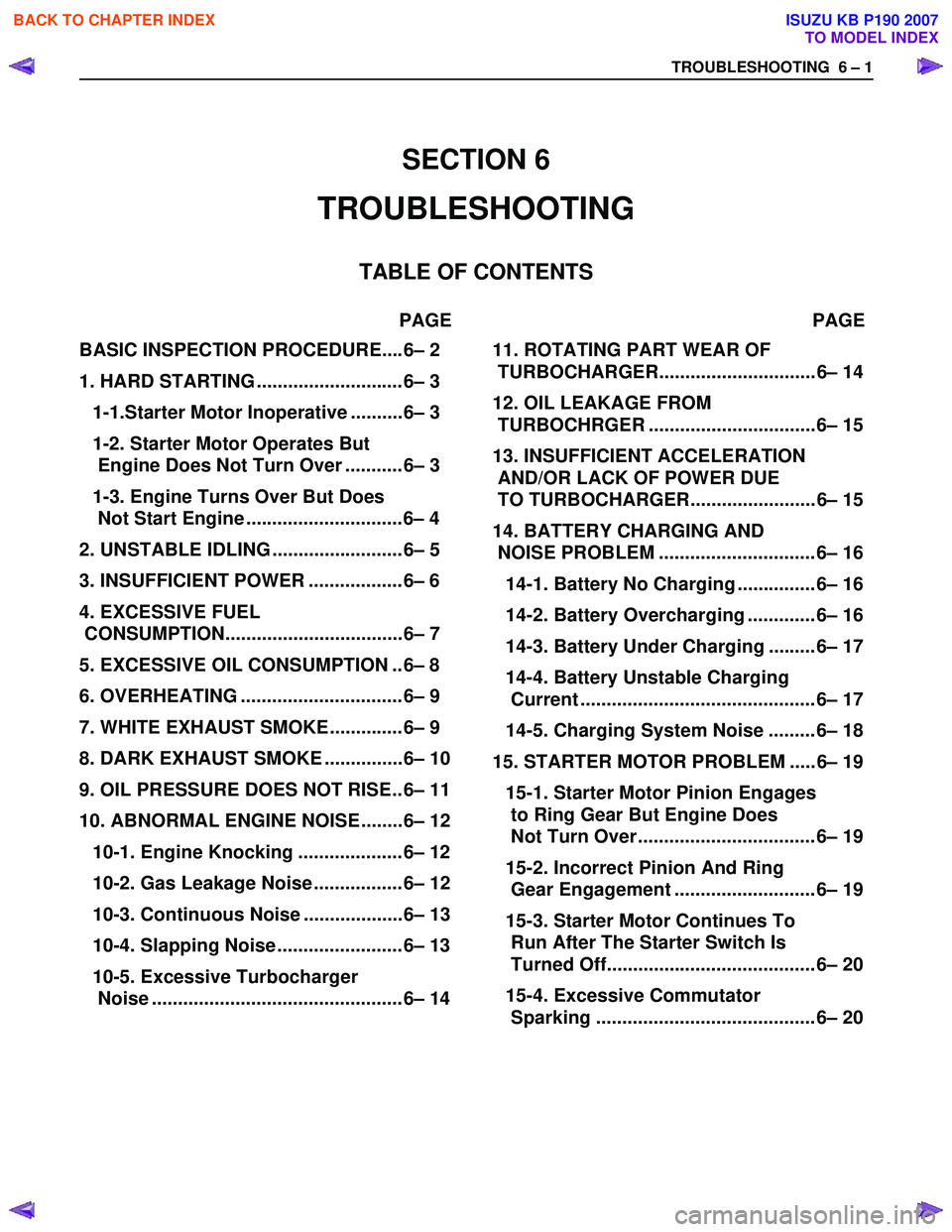
TROUBLESHOOTING 6 – 1
BASIC INSPECTION PROCEDURE....6– 2
1. HARD STARTING ............................6– 3
1-1.Starter Motor Inoperative ..........6– 3
1-2. Starter Motor Operates But
Engine Does Not Turn Over ...........6– 3
1-3. Engine Turns Over But Does
Not Start Engine ..............................6– 4
2. UNSTABLE IDLING .........................6– 5
3. INSUFFICIENT POWER ..................6– 6
4. EXCESSIVE FUEL
CONSUMPTION..................................6– 7
5. EXCESSIVE OIL CONSUMPTION ..6– 8
6. OVERHEATING ...............................6– 9
7. WHITE EXHAUST SMOKE..............6– 9
8. DARK EXHAUST SMOKE ...............6– 10
9. OIL PRESSURE DOES NOT RISE..6– 11
10. ABNORMAL ENGINE NOISE ........6– 12
10-1. Engine Knocking ....................6– 12
10-2. Gas Leakage Noise .................6– 12
10-3. Continuous Noise ...................6– 13
10-4. Slapping Noise ........................6– 13
10-5. Excessive Turbocharger
Noise ................................................6– 14
11. ROTATING PART WEAR OF
TURBOCHARGER.............................. 6– 14
12. OIL LEAKAGE FROM
TURBOCHRGER ................................ 6– 15
13. INSUFFICIENT ACCELERATION
AND/OR LACK OF POWER DUE
TO TURBOCHARGER........................ 6– 15
14. BATTERY CHARGING AND
NOISE PROBLEM .............................. 6– 16
14-1. Battery No Charging ............... 6– 16
14-2. Battery Overcharging ............. 6– 16
14-3. Battery Under Charging ......... 6– 17
14-4. Battery Unstable Charging
Current ............................................. 6– 17
14-5. Charging System Noise ......... 6– 18
15. STARTER MOTOR PROBLEM ..... 6– 19
15-1. Starter Motor Pinion Engages
to Ring Gear But Engine Does
Not Turn Over .................................. 6– 19
15-2. Incorrect Pinion And Ring
Gear Engagement ........................... 6– 19
15-3. Starter Motor Continues To
Run After The Starter Switch Is
Turned Off........................................ 6– 20
15-4. Excessive Commutator
Sparking .......................................... 6– 20
SECTION 6
TROUBLESHOOTING
TABLE OF CONTENTS
PAGE PAGE
BACK TO CHAPTER INDEX
TO MODEL INDEX
ISUZU KB P190 2007
Page 794 of 6020

TROUBLESHOOTING 6 – 9
6. Overheating
Step Action Value(s) Yes No
1 Was the engine coolant level OK? —
Go to Step 2 Replenish the
coolant
2 Was the water leakage or the radiator restriction found? (Include radiator cap) —
Repair or
replace the
leakage part. Go to Step 3
3 Was the fan belt slippage found? — Tension or
replace the fan belt. Go to Step 4
4 Was the fan clutch working completely? —
Go to Step 5 Replace the fan
clutch
assembly.
5 Was the oil leakage found from fan clutch? — Replace the fan
clutch
assembly Go to Step 6
6 Was the thermostat working normally? —
Go to Step 7 Replace the
thermostat.
7 Was the water pump working OK? —
Go to Step 8 Replace the
water pump assembly.
8 Was the restriction by the foreign materials in the cooling system found? For example, clog the water
hose between the cylinder body and radiator etc.. —
Clean or
replace the clog part. Go to Step 9
9 Was the water leakage found from the sealing cap
on the cylinder body? —
Replace the
sealing cap or replace the
cylinder body. Go to Step 10
10 Are any DTC stored? — Go to indicated
DTC. Solved
7. White Exhaust Smoke
Step Action Value(s) Yes No
1 Was the compression pressure OK? 3.0 MPa
(31.0 kg/cm2,
441 psi) at 200 rpm
Go to Step 2 Readjust the
valve clearance or replace the cylinder head gasket or
cylinder liner or
piston or piston ring or valve and relation parts.
2 Was the PCV (Positive Crankcase Ventilation) valve working completely? —
Go to Step 3 Repair or
replace the
PCV valve.
3 Was the turbocharger working completely? —
Go to Step 4 Replace the
turbocharger.
4 Are any DTC stored? — Go to indicated
DTC Solved
BACK TO CHAPTER INDEX
TO MODEL INDEX
ISUZU KB P190 2007
Page 951 of 6020
ENGINE COOLING 6B – 7
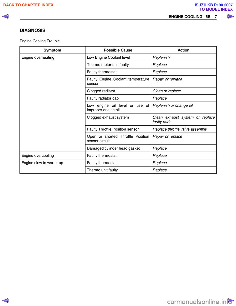
DIAGNOSIS
Engine Cooling Trouble
Symptom Possible Cause Action
Low Engine Coolant level Replenish
Thermo meter unit faulty Replace
Faulty thermostat Replace
Faulty Engine Coolant temperature
sensor Repair or replace
Clogged radiator
Clean or replace
Faulty radiator cap Replace
Low engine oil level or use of
improper engine oil Replenish or change oil
Clogged exhaust system
Clean exhaust system or replace
faulty parts
Faulty Throttle Position sensor Replace throttle valve assembly
Open or shorted Throttle Position
sensor circuit Repair or replace
Engine overheating
Damaged cylinder head gasket Replace
Engine overcooling Faulty thermostat Replace
Faulty thermostat Replace Engine slow to warm–up
Thermo unit faulty Replace
BACK TO CHAPTER INDEX
TO MODEL INDEX
ISUZU KB P190 2007
Page 961 of 6020
ENGINE COOLING 6B – 17
Inspection and Repair
Make the necessary adjustments, repairs, and part
replacements if excessive wear or damage is discovered
during inspection.
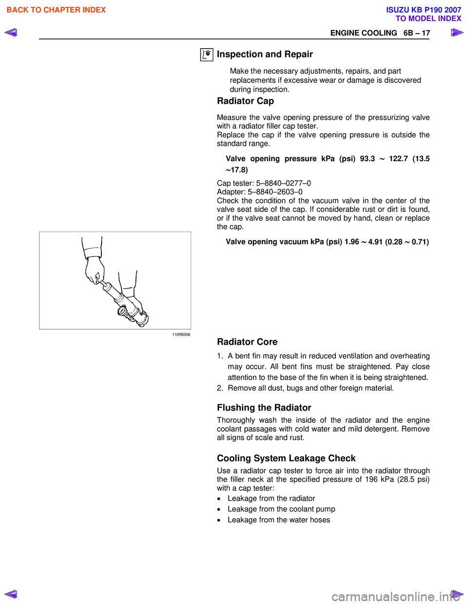
Radiator Cap
Measure the valve opening pressure of the pressurizing valve
with a radiator filler cap tester.
Replace the cap if the valve opening pressure is outside the
standard range.
Valve opening pressure kPa (psi) 93.3
∼
∼∼
∼122.7 (13.5
∼
∼∼
∼17.8)
Cap tester: 5–8840–0277–0
Adapter: 5–8840–2603–0
Check the condition of the vacuum valve in the center of the
valve seat side of the cap. If considerable rust or dirt is found,
or if the valve seat cannot be moved by hand, clean or replace
the cap.
110RS006
Valve opening vacuum kPa (psi) 1.96 ∼
∼∼
∼ 4.91 (0.28 ∼
∼∼
∼ 0.71)
Radiator Core
1. A bent fin may result in reduced ventilation and overheating
may occur. All bent fins must be straightened. Pay close
attention to the base of the fin when it is being straightened.
2. Remove all dust, bugs and other foreign material.
Flushing the Radiator
Thoroughly wash the inside of the radiator and the engine
coolant passages with cold water and mild detergent. Remove
all signs of scale and rust.
Cooling System Leakage Check
Use a radiator cap tester to force air into the radiator through
the filler neck at the specified pressure of 196 kPa (28.5 psi)
with a cap tester:
• Leakage from the radiator
• Leakage from the coolant pump
• Leakage from the water hoses
BACK TO CHAPTER INDEX
TO MODEL INDEX
ISUZU KB P190 2007
Page 1096 of 6020
6E-62 Engine Control System (4JH1)
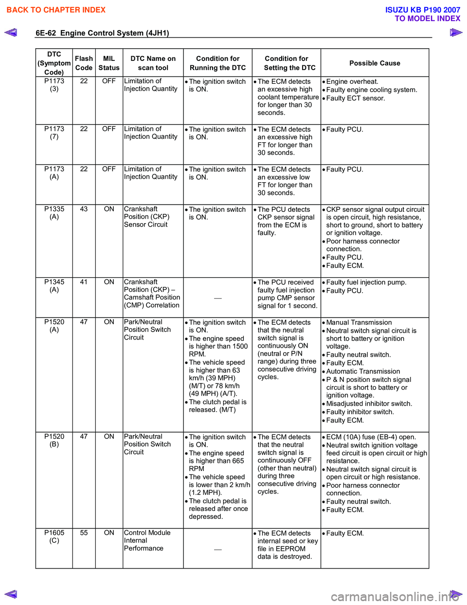
DTC
(Symptom Code) Flash
Code MIL
Status DTC Name on
scan tool Condition for
Running the DTC Condition for
Setting the DTC Possible Cause
P1173
(3) 22 OFF Limitation of
Injection Quantity •
The ignition switch
is ON. •
The ECM detects
an excessive high
coolant temperature
for longer than 30
seconds.
•
Engine overheat.
• Faulty engine cooling system.
• Faulty ECT sensor.
P1173 (7) 22 OFF Limitation of
Injection Quantity
•
The ignition switch
is ON. •
The ECM detects
an excessive high
FT for longer than
30 seconds.
•
Faulty PCU.
P1173 (A) 22 OFF Limitation of
Injection Quantity
•
The ignition switch
is ON. •
The ECM detects
an excessive low
FT for longer than
30 seconds.
•
Faulty PCU.
P1335 (A) 43 ON Crankshaft
Position (CKP)
Sensor Circuit •
The ignition switch
is ON. •
The PCU detects
CKP sensor signal
from the ECM is
faulty.
•
CKP sensor signal output circuit
is open circuit, high resistance,
short to ground, short to battery
or ignition voltage.
• Poor harness connector
connection.
• Faulty PCU.
• Faulty ECM.
P1345 (A) 41 ON Crankshaft
Position (CKP) –
Camshaft Position
(CMP) Correlation
•
The PCU received
faulty fuel injection
pump CMP sensor
signal for 1 second.
•
Faulty fuel injection pump.
• Faulty PCU.
P1520 (A) 47 ON Park/Neutral
Position Switch
Circuit •
The ignition switch
is ON.
• The engine speed
is higher than 1500
RPM.
• The vehicle speed
is higher than 63
km/h (39 MPH)
(M/T) or 78 km/h
(49 MPH) (A/T).
• The clutch pedal is
released. (M/T)
•
The ECM detects
that the neutral
switch signal is
continuously ON
(neutral or P/N
range) during three
consecutive driving
cycles.
•
Manual Transmission
• Neutral switch signal circuit is
short to battery or ignition
voltage.
• Faulty neutral switch.
• Faulty ECM.
• Automatic Transmission
• P & N position switch signal
circuit is short to battery or
ignition voltage.
• Misadjusted inhibitor switch.
• Faulty inhibitor switch.
• Faulty ECM.
P1520 (B) 47 ON Park/Neutral
Position Switch
Circuit •
The ignition switch
is ON.
• The engine speed
is higher than 665
RPM
• The vehicle speed
is lower than 2 km/h
(1.2 MPH).
• The clutch pedal is
released after once
depressed.
•
The ECM detects
that the neutral
switch signal is
continuously OFF
(other than neutral)
during three
consecutive driving
cycles.
•
ECM (10A) fuse (EB-4) open.
• Neutral switch ignition voltage
feed circuit is open circuit or high
resistance.
• Neutral switch signal circuit is
open circuit or high resistance.
• Poor harness connector
connection.
• Faulty neutral switch.
• Faulty ECM.
P1605 (C) 55 ON Control Module
Internal
Performance •
The ECM detects
internal seed or key
file in EEPROM
data is destroyed.
•
Faulty ECM.
BACK TO CHAPTER INDEX
TO MODEL INDEX
ISUZU KB P190 2007
Page 1238 of 6020

6E-204 Engine Control System (4JH1)
DTC P1173 (Symptom Code 3) (Flash Code 22)
Circuit Description
The engine coolant temperature (ECT) sensor is
installed to the thermostat housing. The ECT sensor is
a variable resistor. The ECT sensor has a signal circuit
and a low reference circuit. The ECT sensor measures
the temperature of the engine coolant. The engine
control module (ECM) supplies 5 volts to the ECT signal
circuit and a ground for the ECT low reference circuit.
W hen the ECT sensor is cold, the sensor resistance is
high. W hen the engine coolant temperature increases,
the sensor resistance decreases. W ith high senso
r
resistance, the ECM detects a high voltage on the ECT
signal circuit. W ith lower sensor resistance, the ECM
detects a lower voltage on the ECT signal circuit. If the
ECM detects an excessive high coolant temperature,
this DTC will set.
Condition for Running the DTC
• The ignition switch is ON.
Condition for Setting the DTC • The ECM detects an excessive high coolant
temperature for longer than 30 seconds.
Action Taken When the DTC Sets • The ECM does not illuminate the malfunction
indicator lamp (MIL) when the diagnostic runs and
fails.
Condition for Clearing the DTC
• A history DTC clears after 40 consecutive driving
cycles without a fault. Or clear with the scan tool.
Diagnostic Aids
• If an intermittent condition is suspected, refer to
Intermittent Conditions in this section.
•
After starting the engine, the ECT should rise
steadily to about 80°C – 85°C (176°F – 185°F)
then stabilize when the thermostat opens.
• Use the Temperature vs. Resistance table to test
the ECT sensor at various temperature levels to
evaluate the possibility of a skewed sensor.
A
skewed sensor could result in poor driveabilit
y
concerns.
Notice: • This DTC is caused by an engine overheat
condition (i.e. low engine coolant level). Since this
DTC does not illuminate any lamps, clear the DTC
and ensure there are no signs of engine damage.
Excessive engine overheat may damage internal
engine components.
DTC P1173 (Symptom Code 3) (Flash Code 22)
Step Action Value(s) Yes No
1 Did you perform the Diagnostic System Check-
Engine Controls?
Go to Step 2 Go to Diagnostic
System Check-
Engine Controls
2 1. Install the scan tool. 2. Turn OFF the ignition for 30 seconds.
3. Start the engine and wait until engine is fully warms upped.
4. Observe the Engine Coolant Temperature (ECT) parameter with the scan tool.
Is the ECT parameter more than the specified
value? 100°C (212°F)
Go to Step 4 Go to Step 3
3 Ask the driver if overheat is caused by low engine coolant level, etc.
If engine overheat has experienced, the engine must
be inspected and repaired as necessary.
Did you complete the action?
Go to Step 6
4 1. Test the ECT sensor at various temperature
levels to evaluate the possibility if a skewed
sensor.
2. Replace the ECT sensor as necessary.
Did you find and correct the condition?
Go to Step 6 Go to Step 5
BACK TO CHAPTER INDEX
TO MODEL INDEX
ISUZU KB P190 2007
Page 1302 of 6020

6E-268 Engine Control System (4JH1)
Checks Action
Engine Mechanical Check Inspect the engine mechanical for the following conditions. Refer to the Engine
Mechanical section.
• Inspect for poor cylinder compression. Proper compression is more than 2100 kPa
(309 psi).
• Improper mechanical timing
• Improper valve gap
• Broken or weak valve springs
• W orn camshaft lobes
Additional Checks •
Inspect the generator output voltage. Repair if less than 9 volts or more than 16
volts.
• Inspect the EGR system operating correctly.
• Inspect the engine overheat condition. Refer to the Engine Cooling section.
• Inspect the A/C operation.
• Inspect the torque converter clutch (TCC) operation (A/T only).
Hesitation, Sag, Stumble
Checks Action
DEFINITION:The vehicle has a momentary lack of response when pushing down on the accelerator. The condition can occur
at any vehicle speed. The condition is usually most severe when trying to make the vehicle move from a stop. If severe
enough, the condition may cause the engine to stall.
Preliminary Checks • Diagnostic System Check - Engine Controls.
• Compare the vehicle with a similar unit. Ensure the vehicle has an actual problem.
• Remove the air cleaner and check for dirt, or for air ducts being plugged or
restricted. Replace as necessary.
• Inspect for a proper transmission shift pattern and down shift operation.
• Inspect the fuel quality (cetane index).
• Inspect the engine oil level and quality.
• Inspect the scan tool Data List in this section.
• Inspect the engine control module (ECM) and fuel injection pump control unit (PCU)
grounds for being clean, tight, and in their proper locations.
• Inspect the Service Bulletins for ECM software updates.
Sensor Checks Inspect the engine control sensors for the following conditions. Refer to the scan tool
Data List in this section.
• Use the scan tool to compare the Engine Coolant Temperature (ECT) with the Intake
Air Temperature (IAT) and Fuel Temperature (FT) on a cold engine condition. If the
difference among temperature reading is more than 5°C (9°F) on a cold engine,
check for high resistance on the low reference circuit and signal circuit or for a
skewed sensor.
Notice: The mass air flow (MAF) sensor is heated and as a result the IAT sensor may
indicate a higher than normal intake air temperature if the ignition switch is being ON.
FT sensor is internal to the PCU and it is part of the fuel injection pump assembly.
• Use the scan tool to compare the MAF Sensor parameter with the Desired MAF
parameter. Start the engine and warm up (allow engine coolant temperature to reach
at least 60°C [140°F]). The MAF Sensor parameter must follow the Desired MAF
parameter within 100 mg/strk. If not, inspect the air intake system, EGR system
components and contaminated, skewed or slow MAF sensor.
• Use the scan tool to observe the Accelerator Pedal Position Accelerator Pedal
Position. Accelerator Pedal Position parameter should change linearly from 0% to
100% according to the accelerator pedal operation.
BACK TO CHAPTER INDEX
TO MODEL INDEX
ISUZU KB P190 2007
Page 1529 of 6020
6B-6 ENGINE COOLING (4JK1/4JJ1)
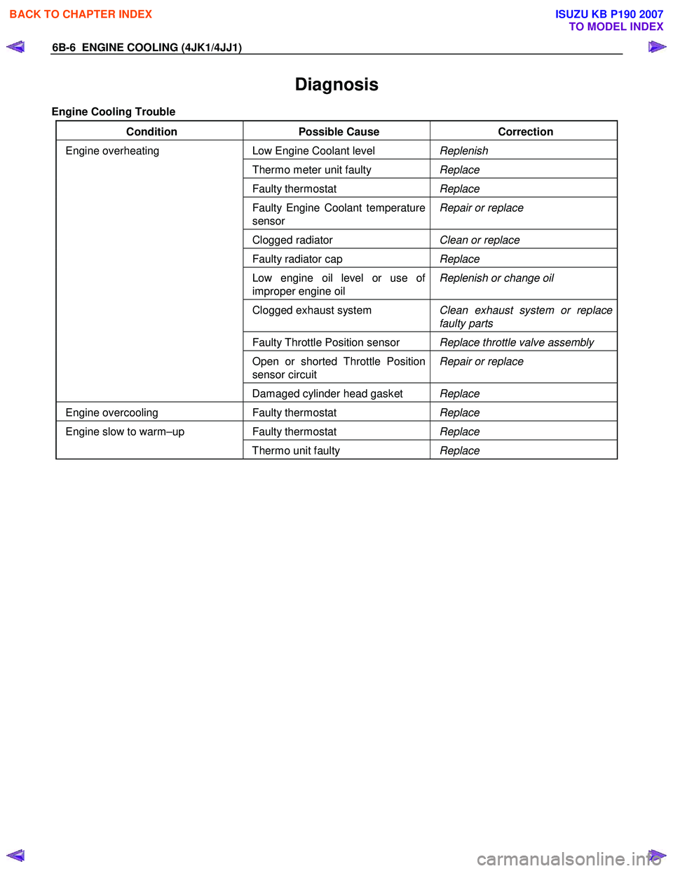
Diagnosis
Engine Cooling Trouble
Condition Possible Cause Correction
Low Engine Coolant level Replenish
Thermo meter unit faulty Replace
Faulty thermostat Replace
Faulty Engine Coolant temperature
sensor Repair or replace
Clogged radiator
Clean or replace
Faulty radiator cap Replace
Low engine oil level or use of
improper engine oil Replenish or change oil
Clogged exhaust system
Clean exhaust system or replace
faulty parts
Faulty Throttle Position sensor Replace throttle valve assembly
Open or shorted Throttle Position
sensor circuit Repair or replace
Engine overheating
Damaged cylinder head gasket Replace
Engine overcooling Faulty thermostat Replace
Faulty thermostat Replace Engine slow to warm–up
Thermo unit faulty Replace
BACK TO CHAPTER INDEX
TO MODEL INDEX
ISUZU KB P190 2007
Page 1538 of 6020
ENGINE COOLING (4JK1/4JJ1) 6B-15
Inspection and Repair
Make the necessary adjustments, repairs, and part
replacements if excessive wear or damage is
discovered during inspection.
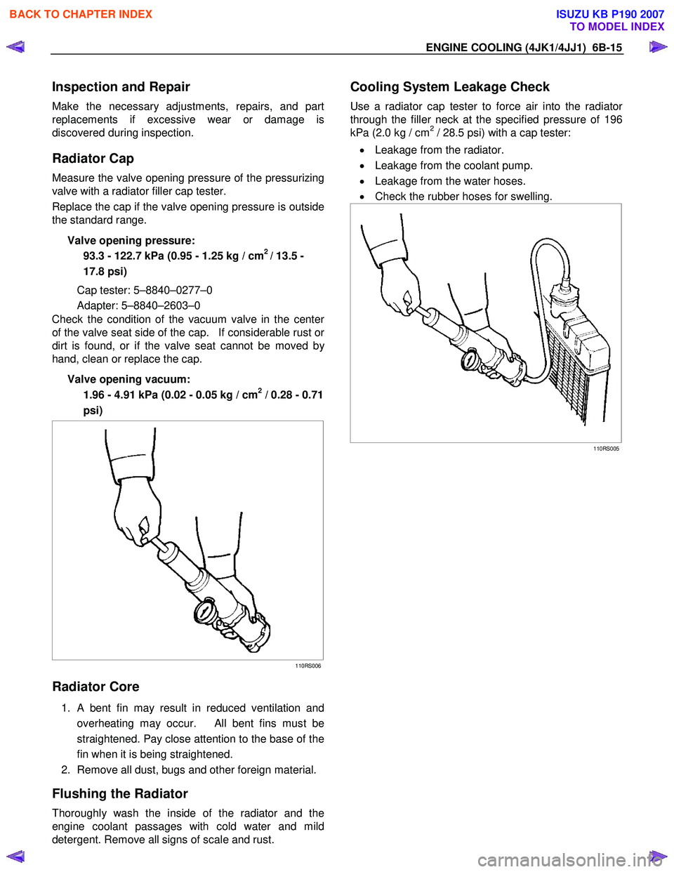
Radiator Cap
Measure the valve opening pressure of the pressurizing
valve with a radiator filler cap tester.
Replace the cap if the valve opening pressure is outside
the standard range.
Valve opening pressure: 93.3 - 122.7 kPa (0.95 - 1.25 kg / cm
2 / 13.5 -
17.8 psi)
Cap tester: 5–8840–0277–0
Adapter: 5–8840–2603–0
Check the condition of the vacuum valve in the cente
r
of the valve seat side of the cap. If considerable rust or
dirt is found, or if the valve seat cannot be moved by
hand, clean or replace the cap.
Valve opening vacuum: 1.96 - 4.91 kPa (0.02 - 0.05 kg / cm
2 / 0.28 - 0.71
psi)
110RS006
Radiator Core
1. A bent fin may result in reduced ventilation and
overheating may occur. All bent fins must be
straightened. Pay close attention to the base of the
fin when it is being straightened.
2. Remove all dust, bugs and other foreign material.
Flushing the Radiator
Thoroughly wash the inside of the radiator and the
engine coolant passages with cold water and mild
detergent. Remove all signs of scale and rust.
Cooling System Leakage Check
Use a radiator cap tester to force air into the radiator
through the filler neck at the specified pressure of 196
kPa (2.0 kg / cm2 / 28.5 psi) with a cap tester:
• Leakage from the radiator.
• Leakage from the coolant pump.
• Leakage from the water hoses.
• Check the rubber hoses for swelling.
110RS005
BACK TO CHAPTER INDEX
TO MODEL INDEX
ISUZU KB P190 2007
Page 1671 of 6020
6E-54 ENGINE CONTROL SYSTEM (4JK1/4JJ1)
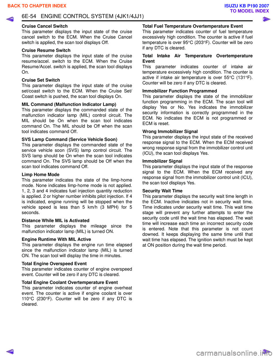
Cruise Cancel Switch
This parameter displays the input state of the cruise
cancel switch to the ECM. When the Cruise Cancel
switch is applied, the scan tool displays Off.
Cruise Resume Switch
This parameter displays the input state of the cruise
resume/accel. switch to the ECM. When the Cruise
Resume/Accel. switch is applied, the scan tool displays
On.
Cruise Set Switch
This parameter displays the input state of the cruise
set/coast switch to the ECM. When the Cruise Set/
Coast switch is pushed, the scan tool displays On.
MIL Command (Malfunction Indicator Lamp)
This parameter displays the commanded state of the
malfunction indicator lamp (MIL) control circuit. The
MIL should be On when the scan tool indicates
command On. The MIL should be Off when the scan
tool indicates command Off.
SVS Lamp Command (Service Vehicle Soon)
This parameter displays the commanded state of the
service vehicle soon (SVS) lamp control circuit. The
SVS lamp should be On when the scan tool indicates
command On. The SVS lamp should be Off when the
scan tool indicates command Off.
Limp Home Mode
This parameter indicates the state of the limp-home
mode. None indicates limp-home mode is not applied.
1, 2, 3 and 4 indicates fuel injection quantity reduction
is applied. 2 or higher number inhibits pilot injection. If 4
is indicated, engine running will be stopped when the
vehicle speed is less than 5 km/h (3 MPH) for 5
seconds.
Distance While MIL is Activated
This parameter displays the mileage since the
malfunction indicator lamp (MIL) is turned ON.
Engine Runtime With MIL Active
This parameter displays the engine run time elapsed
since the malfunction indicator lamp (MIL) is turned
ON. The scan tool will display the time in minutes.
Total Engine Overspeed Event
This parameter indicates counter of engine overspeed
event. Counter will be zero if any DTC is cleared.
Total Engine Coolant Overtemperature Event
This parameter indicates counter of engine overheat
event. The counter is active if engine coolant is over
11 0 °C (230 °F). Counter will be zero if any DTC is
cleared. Total Fuel Temperature Overtemperature Event
This parameter indicates counter of fuel temperature
excessively high condition. The counter is active if fuel
temperature is over 95 °C (203 °F). Counter will be zero
if any DTC is cleared.
Total Intake Air Temperature Overtemperature
Event
This parameter indicates counter of intake air
temperature excessively high condition. The counter is
active if intake air temperature is over 55 °C (131 °F).
Counter will be zero if any DTC is cleared.
Immobilizer Function Programmed
This parameter displays the state of the immobilizer
function programming in the ECM. The scan tool will
display Yes or No. Yes indicates the immobilizer
security information is correctly programmed in the
ECM. No indicates the ECM is not programmed or
ECM is reset.
Wrong Immobilizer Signal
This parameter displays the input state of the received
response signal to the ECM. When the ECM received
wrong response signal from the immobilizer control unit
(ICU), the scan tool displays Yes.
Immobilizer Signal
This parameter displays the input state of the response
signal to the ECM. When the ECM received any
response signal from the immobilizer control unit (ICU),
the scan tool displays Yes.
Security Wait Time
This parameter displays the security wait time length in
the ECM. Inactive indicates not in security wait time.
Time indicates under security wait time. This wait time
stage will prevent any further attempts to enter the
security code until the wait time has elapsed. The wait
time will increase each time an incorrect security code
is entered. Note that this parameter is not count
downed. It keeps displaying the same time until that
wait time has elapsed. The ignition switch must be kept
at ON position during the wait time period.
BACK TO CHAPTER INDEX
TO MODEL INDEX
ISUZU KB P190 2007