park assist ISUZU KB P190 2007 Workshop Repair Manual
[x] Cancel search | Manufacturer: ISUZU, Model Year: 2007, Model line: KB P190, Model: ISUZU KB P190 2007Pages: 6020, PDF Size: 70.23 MB
Page 618 of 6020
BRAKE CONTROL SYSTEM 5A-25
“ABS” Warning Lamp
W hen ABS and problems occur that actuate the “ABS”
warning lamp, the code corresponding to the problem is
stored in the EHCU. Only ordinary braking is available
when the ABS is deactivated. Even when the “ABS”
warning lamp is actuated, if the starter switch is set ON
after setting it OFF once, the EHCU checks up on the
entire system. If there is no abnormality, the EHCU
judges ABS to work correctly and the warning lamp is lit
normally, even though the problem code is stored.
NOTE: Illumination of the “ABS” warning lamp indicates
that anti-lock braking is no longer available. Power
assisted braking without anti-lock control is still
available.
Normal Operation
“ABS ” Warning Lamp
W hen the ignition is first moved from “OFF” to “RUN”,
the amber “ABS” warning lamp will turn “ON”. The
“ABS” warning lamp will turn “ON” during engine
starting and will usually stay “ON” for approximately
three seconds after the ignition switch is returned to the
“ON” position. The warning lamp should remain “OFF”
at all other times.
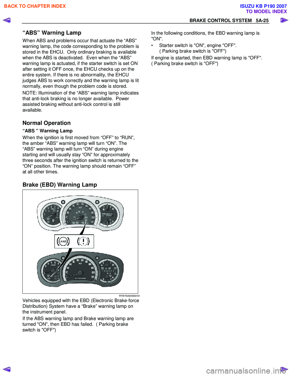
Brake (EBD) Warning Lamp
RTW 75ASH000101
Vehicles equipped with the EBD (Electronic Brake-force
Distribution) System have a “Brake” warning lamp on
the instrument panel.
If the ABS warning lamp and Brake warning lamp are
turned "ON", then EBD has failed. ( Parking brake
switch is "OFF")
In the following conditions, the EBD warning lamp is
"ON".
• Starter switch is "ON", engine "OFF". ( Parking brake switch is "OFF")
If engine is started, then EBD warning lamp is "OFF".
( Parking brake switch is "OFF")
BACK TO CHAPTER INDEX
TO MODEL INDEX
ISUZU KB P190 2007
Page 2519 of 6020
Engine Mechanical – V6 Page 6A1–40
Cause Correction
W orn valve guides and or valve stems. Inspect and repair valves and valve guides as required,
refer to 3.22 Cylinder Head Assembly.
W orn or damaged valve stem oil seal. Replace valve stem oil seals as required, refer to 3.22
Cylinder Head Assembly.
Piston rings broken, worn or not seated correctly. Allowing adequate time for the piston rings to seat correctly,
replace piston rings as required, refer to 4.5 Pistons, Pins,
Rings, Connecting Rods and Big-end Bearings.
Piston rings incorrectly installed or not matched to cylinder
bore oversize. Replace piston rings as required, refer to 4.5 Pistons, Pins,
Rings, Connecting Rods and Big-end Bearings.
2.18 Engine Oil Leak Diagnosis
Introduction
It is important to correctly identify the source of an engine oil leak. For example, a power steering fluid leak or spillage
during servicing can travel across the valley area of the engine and run-out the weep hole, which is located at the back of
the cylinder block. Failure to correctly identify the source of an engine oil leak can lead to unnecessary replacement of
engine components.
Most fluid leaks can be repaired by repairing or replacing the faulty component or resealing the gasket surface. However,
once a leak is identified it is important to determine and repair the cause as well as the leak itself.
Locating and Identifying the Leak
Inspect the leaking fluid and determine whether it is engine oil, transmission fluid, power steering fluid, brake fluid or
some other fluid. If unsure of the source of the leaking lubricant, a quick check of fluid levels should indicate where the
fluid is coming from, as one or more fluid level should be low.
Visual Inspection
Once the type of leaking fluid has been determined, a visual inspection of the affected system should be performed.
W hen performing the visual inspection:
1 Bring the vehicle to the normal operating temperature.
2 Park the vehicle over a large sheet of paper or other clean surface.
3 Leave the vehicle idling for 2-3 minutes, then check for dripping fluid.
4 If required, identify the type of fluid leaking and the approximate location of the leak.
5 Visually inspect the suspected area. A small mirror may assist viewing areas that are difficult to see normally.
6 Check for leaks at all sealing surfaces and fittings.
7 Check for any cracked or damaged components.
8 If the leak cannot be located, completely clean the entire engine and surrounding components, drive the vehicle at normal operating temperature for several kilometres and then repeat Steps 3 to 8.
9 If the leak still cannot be located, proceed with either the Powder Method or Black Light and Dye Method as outlined below.
Powder Method
1 Completely clean the entire engine and surrounding components.
2 Apply an aerosol type powder (e.g. foot powder) to the suspected area.
3 Operate the vehicle at normal operating temperature and at varying speeds for several kilometres.
4 Identify the source of the leak from the discoloration of the powder around the suspect components.
5 If required, use a small mirror to assist in viewing areas that are difficult to see normally.
6 Refer to Possible Causes for Engine Oil Leaks in this Section, and repair or replace components as required.
Black Light and Dye Method
A black light and die kit Tool No. J28428-E or a commercially available equivalent is available to technicians to aid in
engine oil leak diagnosis. W hen using a black light and die kit for the first time, it is recommended the technician read the
manufacturers instructions prior to using the kit.
1 Add the specified amount of dye, as per manufacturers instructions, into the engine or suspected source of the oil leak.
2 Operate the vehicle at normal operating temperature and at varying speeds for several kilometres.
BACK TO CHAPTER INDEX
TO MODEL INDEX
ISUZU KB P190 2007
Page 2825 of 6020
Engine Mechanical – V6 Page 6A1–48
Page 6A1–48
2.18 Engine Oil Leak Diagnosis
Introduction
It is important to correctly identify the source of an engine oil leak. For example, a power steering fluid leak or spillage
during servicing can travel across the va lley area of the engine and run-out the weep hole, which is located at the back of
the cylinder block. Failure to correctly identify the source of an engine oil leak can lead to unnecessary replacement of
engine components.
Most fluid leaks can be repaired by repairi ng or replacing the faulty component or resealing the gasket surface. However,
once a leak is identified it is im portant to determine and repair the c ause as well as the leak itself.
Locating and Identifying the Leak
Inspect the leaking fluid and determine whet her it is engine oil, transmission fluid, power steering fluid, brake fluid or
some other fluid. If unsure of the source of the leaking lubricant, a quick check of fluid levels should indicate where the
fluid is coming from, as one or more fluid level should be low.
Visual Inspection
Once the type of leaking fluid has been determined, a visual inspection of the affected system should be performed.
When performing the visual inspection:
1 Bring the vehicle to the normal operating temperature.
2 Park the vehicle over a large s heet of paper or other clean surface.
3 Leave the vehicle idling for 2-3 minut es, then check for dripping fluid.
4 If required, identify the type of fluid leak ing and the approximate location of the leak.
5 Visually inspect the suspected area. A small mirror may assist viewing areas that are difficult to see normally.
6 Check for leaks at all sealing surfaces and fittings.
7 Check for any cracked or damaged components.
8 If the leak cannot be located, completely clean the entire engine and surrounding components, drive the vehicle at
normal operating temperature for several k ilometres and then repeat Steps 3 to 8.
9 If the leak still cannot be located, proceed with either the Powder Method or Black Light and Dye Method as
outlined below.
Powder Method
1 Completely clean the entir e engine and surrounding components.
2 Apply an aerosol type powder (e.g. f oot powder) to the suspected area.
3 Operate the vehicle at normal operating temperature and at varying speeds for several kilometres.
4 Identify the source of the leak from the discoloration of the powder around the suspect components.
5 If required, use a small mirror to assist in vi ewing areas that are difficult to see normally.
6 Refer to Possible Causes for Engine Oil Leaks in this Section, and repair or replace components as required.
Black Light and Dye Method
A black light and die kit Tool No. J28428-E or a commercially av ailable equivalent is available to technicians to aid in
engine oil leak diagnosis. When using a black light and die kit fo r the first time, it is recommended the technician read the
manufacturers instructions prior to using the kit.
1 Add the specified amount of dye, as per manufacturers instructions, into the engine or suspected source of the oil
leak.
2 Operate the vehicle at normal operating temperature and at varying speeds for several kilometres.
3 With the vehicle parked on a flat leve l surface, aim the black light at the suspected component/s. The dyed fluid will
appear as a yellow path leading to the oil leak source
4 Refer to Possible Causes for Engine Oil Leaks in this Section, and repair or replace components as required.
BACK TO CHAPTER INDEX
TO MODEL INDEX
ISUZU KB P190 2007
Page 3254 of 6020
Engine Management – V6 – General Information Page 6C1-1–12
Battery Voltage Correction Mode
The ECM monitors the battery voltage circuit to ensure the voltage available to the engine management system stays
within the specified range. A low system voltage changes the voltage across the fuel injectors, which affects the fuel
injector flow rate. In addition, a low system voltage fault condition may cause other engine management system
components to malfunction.
The ECM switches to battery voltage correction mode when the ECM detects a low battery voltage fault condition. W hile
in battery voltage correction mode, the ECM performs the following functions to compensate for the low system voltage:
• Increases the injector on-time to maintain the correct amount of fuel being delivered, and
• Increases the idle speed to increase the generator output.
Limp Mode
The programming in the ECM software allows the engine to run in a back-up fuel strategy or limp mode when the ECM
fails to receive signal inputs from critical sensors or when a critical engine management fault condition exists.
The ECM switches to limp mode to enable the vehicle to be driven until service operations can be performed.
Engine Protection Mode
Engine protection mode is engaged to protect engine components from friction damage in the event of an engine over-
temperature condition being detected by the ECM.
W hen the ECM is in engine protection mode, fuel injectors are systematically disabled and re-activated. The injectors
that have been shut down allow the air being drawn into the engine to assist with engine cooling.
Clear Flood Mode
If the engine is flooded with fuel during starting and will not start, the clear flood mode can be manually selected by
depressing the accelerator pedal to wide open throttle (W OT). In this mode, the ECM will completely disable the fuel
injectors, and will maintain this state during engine cranking as long as the ECM detects a W OT condition with engine
speed less than 1,000 rpm.
3.3 Ignition Control System
The electronic ignition system provides a spark to ignite the compressed air / fuel mixture at the correct time. The ECM
maintains correct spark timing and dwell for all engine operating conditions. The ECM calculates the optimum spark
parameters from information received from the various sensors and triggers the appropriate ignition module / coil to fire
the spark plug.
3.4 Starter Motor Operation
The engine control module controls the activation of the start relay in response to inputs from:
• Ignition switch,
• Battery,
• Immobiliser system, and
• Automatic transmission gear selector position / clutch pedal position switch for vehicles with manual transmissions.
3.5 Throttle Actuator Control System
Description
The throttle actuator control (TAC) system is used to improve emissions, fuel economy and driveability. The TAC system
eliminates the mechanical link between the accelerator pedal and the throttle plate and eliminates the need for a cruise
control module and idle air control motor. The TAC system comprises of:
BACK TO CHAPTER INDEX
TO MODEL INDEX
ISUZU KB P190 2007
Page 3384 of 6020
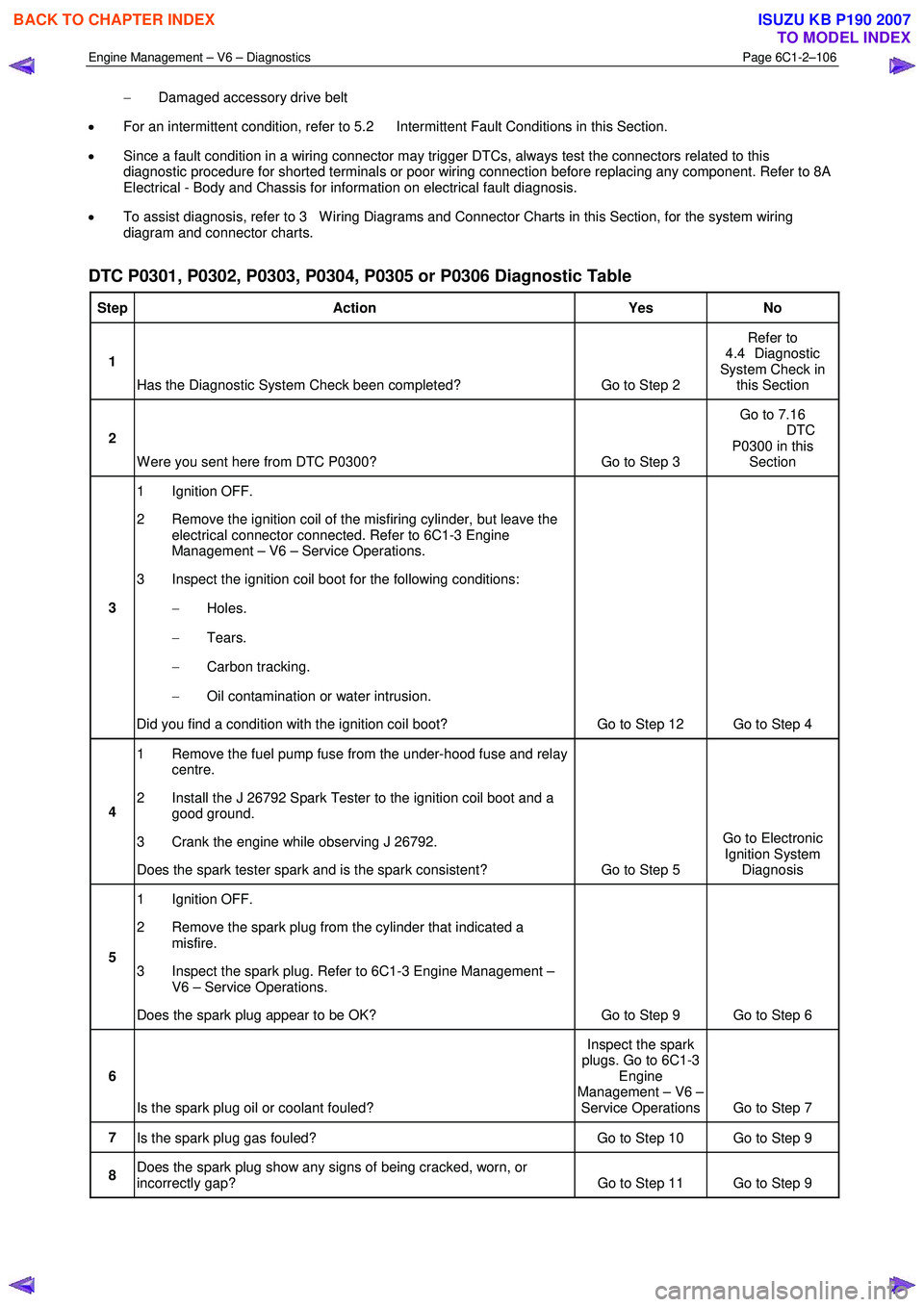
Engine Management – V6 – Diagnostics Page 6C1-2–106
− Damaged accessory drive belt
• For an intermittent condition, refer to 5.2 Intermittent Fault Conditions in this Section.
• Since a fault condition in a wiring connector may trigger DTCs, always test the connectors related to this
diagnostic procedure for shorted terminals or poor wiring connection before replacing any component. Refer to 8A
Electrical - Body and Chassis for information on electrical fault diagnosis.
• To assist diagnosis, refer to 3 W iring Diagrams and Connector Charts in this Section, for the system wiring
diagram and connector charts.
DTC P0301, P0302, P0303, P0304, P0305 or P0306 Diagnostic Table
Step Action Yes No
1
Has the Diagnostic System Check been completed? Go to Step 2 Refer to
4.4 Diagnostic
System Check in this Section
2
W ere you sent here from DTC P0300? Go to Step 3 Go to 7.16
DTC P0300 in this Section
3 1 Ignition OFF.
2 Remove the ignition coil of the misfiring cylinder, but leave the electrical connector connected. Refer to 6C1-3 Engine
Management – V6 – Service Operations.
3 Inspect the ignition coil boot for the following conditions:
− Holes.
− Tears.
− Carbon tracking.
− Oil contamination or water intrusion.
Did you find a condition with the ignition coil boot? Go to Step 12 Go to Step 4
4 1 Remove the fuel pump fuse from the under-hood fuse and relay
centre.
2 Install the J 26792 Spark Tester to the ignition coil boot and a good ground.
3 Crank the engine while observing J 26792.
Does the spark tester spark and is the spark consistent? Go to Step 5 Go to Electronic
Ignition System Diagnosis
5 1 Ignition OFF.
2 Remove the spark plug from the cylinder that indicated a misfire.
3 Inspect the spark plug. Refer to 6C1-3 Engine Management – V6 – Service Operations.
Does the spark plug appear to be OK? Go to Step 9 Go to Step 6
6
Is the spark plug oil or coolant fouled? Inspect the spark
plugs. Go to 6C1-3 Engine
Management – V6 – Service Operations Go to Step 7
7 Is the spark plug gas fouled? Go to Step 10 Go to Step 9
8 Does the spark plug show any signs of being cracked, worn, or
incorrectly gap? Go to Step 11 Go to Step 9
BACK TO CHAPTER INDEX
TO MODEL INDEX
ISUZU KB P190 2007
Page 3397 of 6020
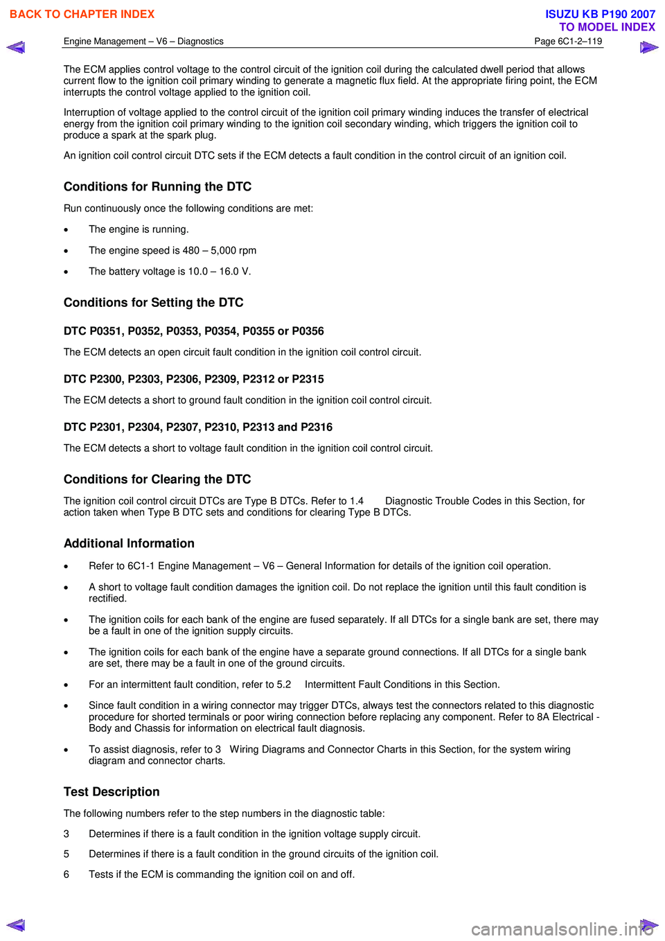
Engine Management – V6 – Diagnostics Page 6C1-2–119
The ECM applies control voltage to the control circuit of the ignition coil during the calculated dwell period that allows
current flow to the ignition coil primary winding to generate a magnetic flux field. At the appropriate firing point, the ECM
interrupts the control voltage applied to the ignition coil.
Interruption of voltage applied to the control circuit of the ignition coil primary winding induces the transfer of electrical
energy from the ignition coil primary winding to the ignition coil secondary winding, which triggers the ignition coil to
produce a spark at the spark plug.
An ignition coil control circuit DTC sets if the ECM detects a fault condition in the control circuit of an ignition coil.
Conditions for Running the DTC
Run continuously once the following conditions are met:
• The engine is running.
• The engine speed is 480 – 5,000 rpm
• The battery voltage is 10.0 – 16.0 V.
Conditions for Setting the DTC
DTC P0351, P0352, P0353, P0354, P0355 or P0356
The ECM detects an open circuit fault condition in the ignition coil control circuit.
DTC P2300, P2303, P2306, P2309, P2312 or P2315
The ECM detects a short to ground fault condition in the ignition coil control circuit.
DTC P2301, P2304, P2307, P2310, P2313 and P2316
The ECM detects a short to voltage fault condition in the ignition coil control circuit.
Conditions for Clearing the DTC
The ignition coil control circuit DTCs are Type B DTCs. Refer to 1.4 Diagnostic Trouble Codes in this Section, for
action taken when Type B DTC sets and conditions for clearing Type B DTCs.
Additional Information
• Refer to 6C1-1 Engine Management – V6 – General Information for details of the ignition coil operation.
• A short to voltage fault condition damages the ignition coil. Do not replace the ignition until this fault condition is
rectified.
• The ignition coils for each bank of the engine are fused separately. If all DTCs for a single bank are set, there may
be a fault in one of the ignition supply circuits.
• The ignition coils for each bank of the engine have a separate ground connections. If all DTCs for a single bank
are set, there may be a fault in one of the ground circuits.
• For an intermittent fault condition, refer to 5.2 Intermittent Fault Conditions in this Section.
• Since fault condition in a wiring connector may trigger DTCs, always test the connectors related to this diagnostic
procedure for shorted terminals or poor wiring connection before replacing any component. Refer to 8A Electrical -
Body and Chassis for information on electrical fault diagnosis.
• To assist diagnosis, refer to 3 W iring Diagrams and Connector Charts in this Section, for the system wiring
diagram and connector charts.
Test Description
The following numbers refer to the step numbers in the diagnostic table:
3 Determines if there is a fault condition in the ignition voltage supply circuit.
5 Determines if there is a fault condition in the ground circuits of the ignition coil.
6 Tests if the ECM is commanding the ignition coil on and off.
BACK TO CHAPTER INDEX
TO MODEL INDEX
ISUZU KB P190 2007
Page 3442 of 6020
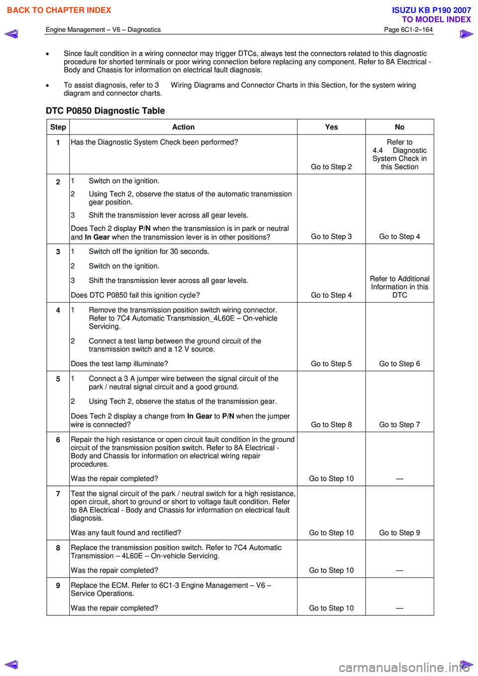
Engine Management – V6 – Diagnostics Page 6C1-2–164
• Since fault condition in a wiring connector may trigger DTCs, always test the connectors related to this diagnostic
procedure for shorted terminals or poor wiring connection before replacing any component. Refer to 8A Electrical -
Body and Chassis for information on electrical fault diagnosis.
• To assist diagnosis, refer to 3 W iring Diagrams and Connector Charts in this Section, for the system wiring
diagram and connector charts.
DTC P0850 Diagnostic Table
Step Action Yes No
1 Has the Diagnostic System Check been performed?
Go to Step 2 Refer to
4.4 Diagnostic
System Check in this Section
2 1 Switch on the ignition.
2 Using Tech 2, observe the status of the automatic transmission gear position.
3 Shift the transmission lever across all gear levels.
Does Tech 2 display P/N when the transmission is in park or neutral
and In Gear when the transmission lever is in other positions? Go to Step 3 Go to Step 4
3
1 Switch off the ignition for 30 seconds.
2 Switch on the ignition.
3 Shift the transmission lever across all gear levels.
Does DTC P0850 fail this ignition cycle? Go to Step 4 Refer to Additional
Information in this DTC
4 1 Remove the transmission position switch wiring connector.
Refer to 7C4 Automatic Transmission_4L60E – On-vehicle
Servicing.
2 Connect a test lamp between the ground circuit of the transmission switch and a 12 V source.
Does the test lamp illuminate? Go to Step 5 Go to Step 6
5 1 Connect a 3 A jumper wire between the signal circuit of the
park / neutral signal circuit and a good ground.
2 Using Tech 2, observe the status of the transmission gear.
Does Tech 2 display a change from In Gear to P/N when the jumper
wire is connected? Go to Step 8 Go to Step 7
6 Repair the high resistance or open circuit fault condition in the ground
circuit of the transmission position switch. Refer to 8A Electrical -
Body and Chassis for information on electrical wiring repair
procedures.
W as the repair completed? Go to Step 10 —
7 Test the signal circuit of the park / neutral switch for a high resistance,
open circuit, short to ground or short to voltage fault condition. Refer
to 8A Electrical - Body and Chassis for information on electrical fault
diagnosis.
W as any fault found and rectified? Go to Step 10 Go to Step 9
8 Replace the transmission position switch. Refer to 7C4 Automatic
Transmission – 4L60E – On-vehicle Servicing.
W as the repair completed? Go to Step 10 —
9 Replace the ECM. Refer to 6C1-3 Engine Management – V6 –
Service Operations.
W as the repair completed? Go to Step 10 —
BACK TO CHAPTER INDEX
TO MODEL INDEX
ISUZU KB P190 2007
Page 3502 of 6020
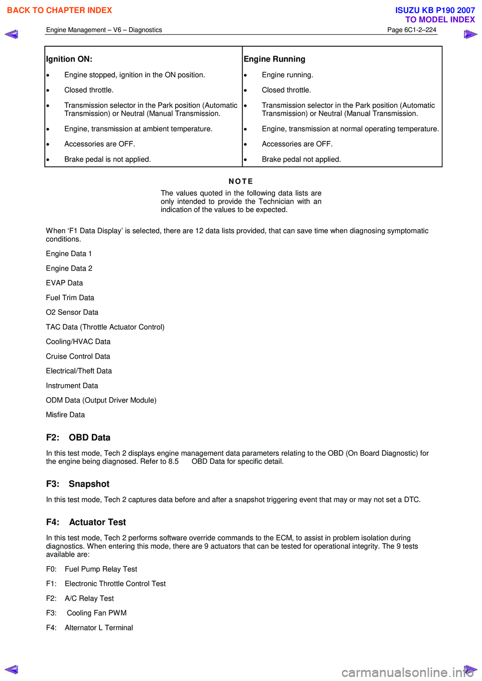
Engine Management – V6 – Diagnostics Page 6C1-2–224
Ignition ON:
• Engine stopped, ignition in the ON position.
• Closed throttle.
• Transmission selector in the Park position (Automatic
Transmission) or Neutral (Manual Transmission.
• Engine, transmission at ambient temperature.
• Accessories are OFF.
• Brake pedal is not applied.
Engine Running
• Engine running.
• Closed throttle.
• Transmission selector in the Park position (Automatic
Transmission) or Neutral (Manual Transmission.
• Engine, transmission at normal operating temperature.
• Accessories are OFF.
• Brake pedal not applied.
NOTE
The values quoted in the following data lists are
only intended to provide the Technician with an
indication of the values to be expected.
W hen ‘F1 Data Display’ is selected, there are 12 data lists provided, that can save time when diagnosing symptomatic
conditions.
Engine Data 1
Engine Data 2
EVAP Data
Fuel Trim Data
O2 Sensor Data
TAC Data (Throttle Actuator Control)
Cooling/HVAC Data
Cruise Control Data
Electrical/Theft Data
Instrument Data
ODM Data (Output Driver Module)
Misfire Data
F2: OBD Data
In this test mode, Tech 2 displays engine management data parameters relating to the OBD (On Board Diagnostic) for
the engine being diagnosed. Refer to 8.5 OBD Data for specific detail.
F3: Snapshot
In this test mode, Tech 2 captures data before and after a snapshot triggering event that may or may not set a DTC.
F4: Actuator Test
In this test mode, Tech 2 performs software override commands to the ECM, to assist in problem isolation during
diagnostics. W hen entering this mode, there are 9 actuators that can be tested for operational integrity. The 9 tests
available are:
F0: Fuel Pump Relay Test
F1: Electronic Throttle Control Test
F2: A/C Relay Test
F3: Cooling Fan PW M
F4: Alternator L Terminal
BACK TO CHAPTER INDEX
TO MODEL INDEX
ISUZU KB P190 2007
Page 3618 of 6020
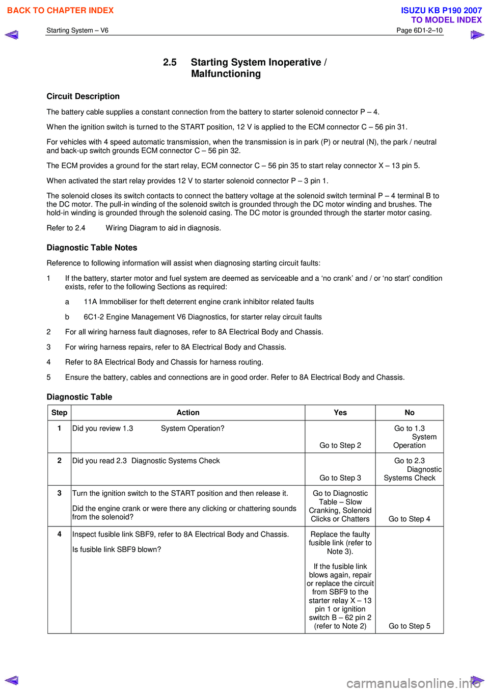
Starting System – V6 Page 6D1-2–10
2.5 Starting System Inoperative /
Malfunctioning
Circuit Description
The battery cable supplies a constant connection from the battery to starter solenoid connector P – 4.
W hen the ignition switch is turned to the START position, 12 V is applied to the ECM connector C – 56 pin 31.
For vehicles with 4 speed automatic transmission, when the transmission is in park (P) or neutral (N), the park / neutral
and back-up switch grounds ECM connector C – 56 pin 32.
The ECM provides a ground for the start relay, ECM connector C – 56 pin 35 to start relay connector X – 13 pin 5.
W hen activated the start relay provides 12 V to starter solenoid connector P – 3 pin 1.
The solenoid closes its switch contacts to connect the battery voltage at the solenoid switch terminal P – 4 terminal B to
the DC motor. The pull-in winding of the solenoid switch is grounded through the DC motor winding and brushes. The
hold-in winding is grounded through the solenoid casing. The DC motor is grounded through the starter motor casing.
Refer to 2.4 W iring Diagram to aid in diagnosis.
Diagnostic Table Notes
Reference to following information will assist when diagnosing starting circuit faults:
1 If the battery, starter motor and fuel system are deemed as serviceable and a ‘no crank’ and / or ‘no start’ condition exists, refer to the following Sections as required:
a 11A Immobiliser for theft deterrent engine crank inhibitor related faults
b 6C1-2 Engine Management V6 Diagnostics, for starter relay circuit faults
2 For all wiring harness fault diagnoses, refer to 8A Electrical Body and Chassis.
3 For wiring harness repairs, refer to 8A Electrical Body and Chassis.
4 Refer to 8A Electrical Body and Chassis for harness routing.
5 Ensure the battery, cables and connections are in good order. Refer to 8A Electrical Body and Chassis.
Diagnostic Table
Step Action Yes No
1
Did you review 1.3 System Operation?
Go to Step 2 Go to 1.3
System
Operation
2 Did you read 2.3 Diagnostic Systems Check
Go to Step 3 Go to 2.3
Diagnostic Systems Check
3 Turn the ignition switch to the START position and then release it.
Did the engine crank or were there any clicking or chattering sounds
from the solenoid? Go to Diagnostic
Table – Slow
Cranking, Solenoid Clicks or Chatters Go to Step 4
4 Inspect fusible link SBF9, refer to 8A Electrical Body and Chassis.
Is fusible link SBF9 blown? Replace the faulty
fusible link (refer to
Note 3).
If the fusible link
blows again, repair
or replace the circuit from SBF9 to the
starter relay X – 13 pin 1 or ignition
switch B – 62 pin 2 (refer to Note 2) Go to Step 5
BACK TO CHAPTER INDEX
TO MODEL INDEX
ISUZU KB P190 2007
Page 3621 of 6020
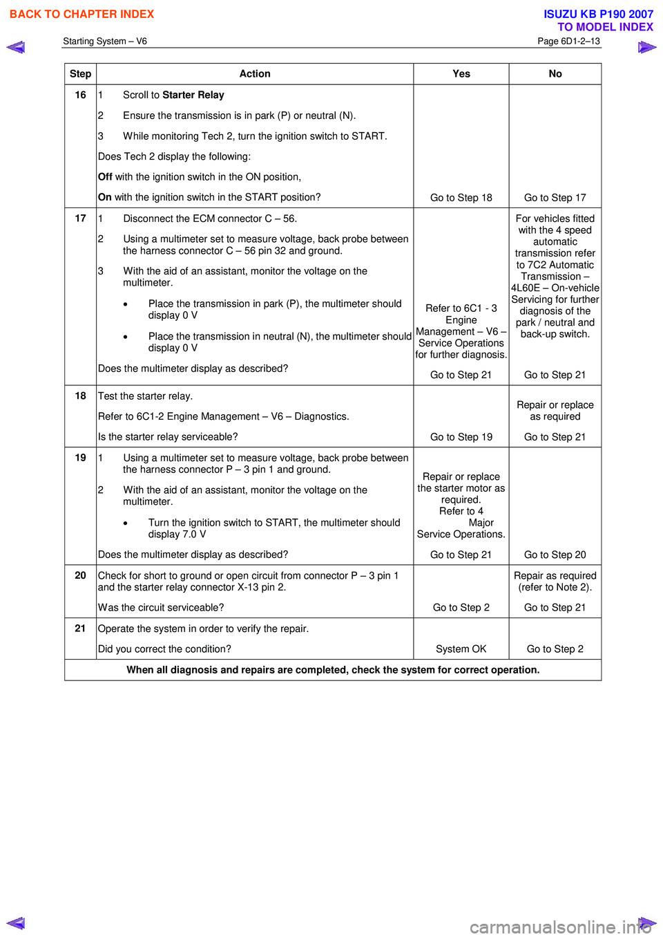
Starting System – V6 Page 6D1-2–13
Step Action Yes No
16 1 Scroll to Starter Relay
2 Ensure the transmission is in park (P) or neutral (N).
3 W hile monitoring Tech 2, turn the ignition switch to START.
Does Tech 2 display the following:
Off with the ignition switch in the ON position,
On with the ignition switch in the START position?
Go to Step 18 Go to Step 17
17 1 Disconnect the ECM connector C – 56.
2 Using a multimeter set to measure voltage, back probe between the harness connector C – 56 pin 32 and ground.
3 W ith the aid of an assistant, monitor the voltage on the multimeter.
• Place the transmission in park (P), the multimeter should
display 0 V
• Place the transmission in neutral (N), the multimeter should
display 0 V
Does the multimeter display as described? Refer to 6C1 - 3
Engine
Management – V6 – Service Operations
for further diagnosis.
Go to Step 21 For vehicles fitted
with the 4 speed automatic
transmission refer
to 7C2 Automatic Transmission –
4L60E – On-vehicle Servicing for further
diagnosis of the
park / neutral and back-up switch.
Go to Step 21
18 Test the starter relay.
Refer to 6C1-2 Engine Management – V6 – Diagnostics.
Is the starter relay serviceable? Go to Step 19 Repair or replace
as required
Go to Step 21
19 1 Using a multimeter set to measure voltage, back probe between
the harness connector P – 3 pin 1 and ground.
2 W ith the aid of an assistant, monitor the voltage on the multimeter.
• Turn the ignition switch to START, the multimeter should
display 7.0 V
Does the multimeter display as described? Repair or replace
the starter motor as required.
Refer to 4
Major
Service Operations.
Go to Step 21 Go to Step 20
20 Check for short to ground or open circuit from connector P – 3 pin 1
and the starter relay connector X-13 pin 2.
W as the circuit serviceable? Go to Step 2 Repair as required
(refer to Note 2).
Go to Step 21
21 Operate the system in order to verify the repair.
Did you correct the condition? System OK Go to Step 2
When all diagnosis and repairs are completed, check the system for correct operation.
BACK TO CHAPTER INDEX
TO MODEL INDEX
ISUZU KB P190 2007