weight ISUZU KB P190 2007 Workshop Repair Manual
[x] Cancel search | Manufacturer: ISUZU, Model Year: 2007, Model line: KB P190, Model: ISUZU KB P190 2007Pages: 6020, PDF Size: 70.23 MB
Page 256 of 6020
3A-8 FRONT ALIGNMENT
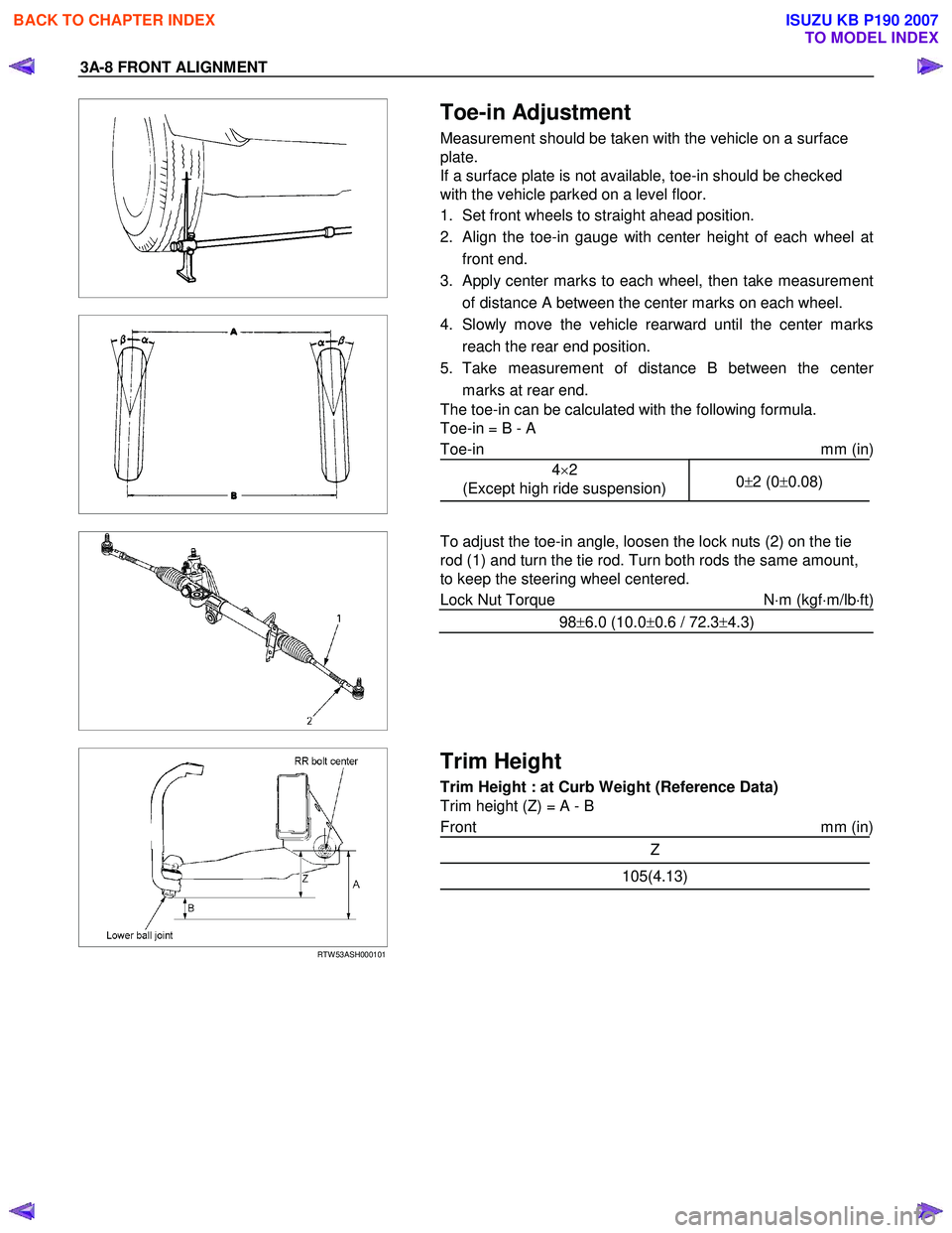
Toe-in Adjustment
Measurement should be taken with the vehicle on a surface
plate.
If a surface plate is not available, toe-in should be checked
with the vehicle parked on a level floor.
1. Set front wheels to straight ahead position.
2. Align the toe-in gauge with center height of each wheel at front end.
3.
Apply center marks to each wheel, then take measurement
of distance A between the center marks on each wheel.
4. Slowly move the vehicle rearward until the center marks reach the rear end position.
5. Take measurement of distance B between the cente
r
marks at rear end.
The toe-in can be calculated with the following formula.
Toe-in = B - A
Toe-in mm (in)
4×2
(Except high ride suspension) 0
±2 (0 ±0.08)
To adjust the toe-in angle, loosen the lock nuts (2) on the tie
rod (1) and turn the tie rod. Turn both rods the same amount,
to keep the steering wheel centered.
Lock Nut Torque N⋅m (kgf ⋅m/lb ⋅ft)
98 ±6.0 (10.0 ±0.6 / 72.3 ±4.3)
RTW 53ASH000101
Trim Height
Trim Height : at Curb Weight (Reference Data)
Trim height (Z) = A - B
Front mm (in)
Z
105(4.13)
BACK TO CHAPTER INDEX
TO MODEL INDEX
ISUZU KB P190 2007
Page 260 of 6020
3A-12 FRONT ALIGNMENT
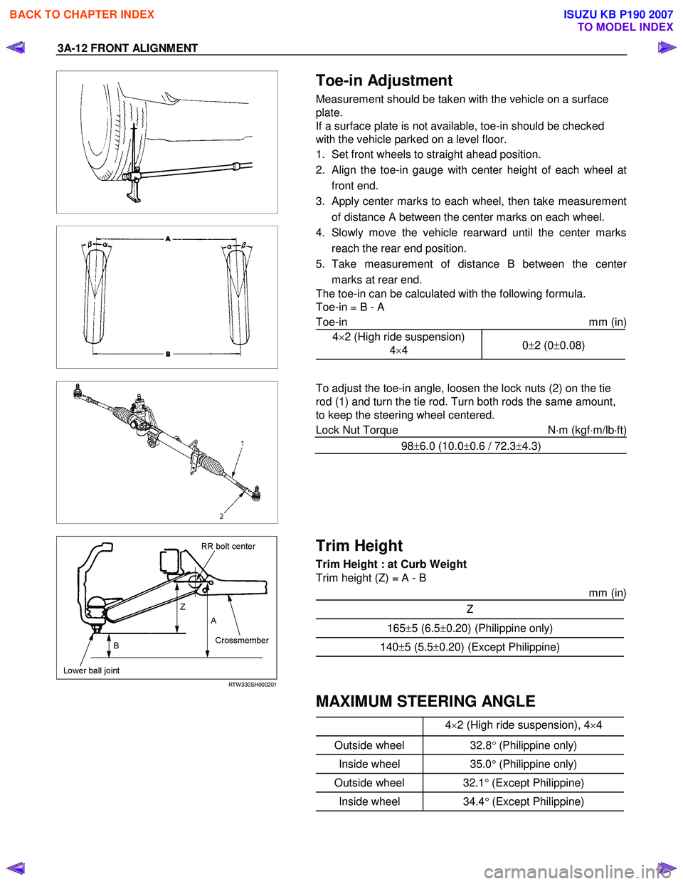
Toe-in Adjustment
Measurement should be taken with the vehicle on a surface
plate.
If a surface plate is not available, toe-in should be checked
with the vehicle parked on a level floor.
1. Set front wheels to straight ahead position.
2. Align the toe-in gauge with center height of each wheel at front end.
3.
Apply center marks to each wheel, then take measurement
of distance A between the center marks on each wheel.
4. Slowly move the vehicle rearward until the center marks reach the rear end position.
5. Take measurement of distance B between the cente
r
marks at rear end.
The toe-in can be calculated with the following formula.
Toe-in = B - A
Toe-in mm (in)
4×2 (High ride suspension)
4×4 0
±2 (0 ±0.08)
To adjust the toe-in angle, loosen the lock nuts (2) on the tie
rod (1) and turn the tie rod. Turn both rods the same amount,
to keep the steering wheel centered.
Lock Nut Torque N⋅m (kgf ⋅m/lb ⋅ft)
98 ±6.0 (10.0 ±0.6 / 72.3 ±4.3)
RTW 330SH000201
Trim Height
Trim Height : at Curb Weight
Trim height (Z) = A - B
mm (in)
Z
165±5 (6.5 ±0.20) (Philippine only)
140 ±5 (5.5 ±0.20) (Except Philippine)
MAXIMUM STEERING ANGLE
4
×2 (High ride suspension), 4 ×4
Outside wheel 32.8° (Philippine only)
Inside wheel 35.0° (Philippine only)
Outside wheel 32.1° (Except Philippine)
Inside wheel 34.4° (Except Philippine)
BACK TO CHAPTER INDEX
TO MODEL INDEX
ISUZU KB P190 2007
Page 451 of 6020
REAR AXLE 4B-7
REAR AXLE ASSEMBLY
General Description
A03R300001
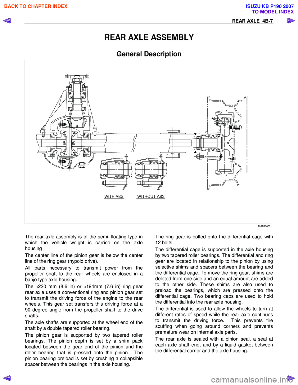
The rear axle assembly is of the semi–floating type in
which the vehicle weight is carried on the axle
housing .
The center line of the pinion gear is below the cente
r
line of the ring gear (hypoid drive).
All parts necessary to transmit power from the
propeller shaft to the rear wheels are enclosed in a
banjo type axle housing.
The φ220 mm (8.6 in) or φ194mm (7.6 in) ring gea
r
rear axle uses a conventional ring and pinion gear set
to transmit the driving force of the engine to the rea
r
wheels. This gear set transfers this driving force at a
90 degree angle from the propeller shaft to the drive
shafts.
The axle shafts are supported at the wheel end of the
shaft by a double tapered roller bearing.
The pinion gear is supported by two tapered rolle
r
bearings. The pinion depth is set by a shim pack
located between the gear end of the pinion and the
roller bearing that is pressed onto the pinion. The
pinion bearing preload is set by crushing a collapsible
spacer between the bearings in the axle housing.
The ring gear is bolted onto the differential cage with
12 bolts.
The differential cage is supported in the axle housing
by two tapered roller bearings. The differential and ring
gear are located in relationship to the pinion by using
selective shims and spacers between the bearing and
the differential cage. To move the ring gear, shims are
deleted from one side and an equal amount are added
to the other side. These shims are also used to
preload the bearings, which are pressed onto the
differential cage. Two bearing caps are used to hold
the differential into the rear axle housing.
The differential is used to allow the wheels to turn at
different rates of speed while the rear axle continues
to transmit the driving force. This prevents tire
scuffing when going around corners and prevents
premature wear on internal axle parts.
The rear axle is sealed with a pinion seal, a seal at
each axle shaft end, and by a liquid gasket between
the differential carrier and the axle housing.
BACK TO CHAPTER INDEX
TO MODEL INDEX
ISUZU KB P190 2007
Page 721 of 6020

5C-22 BRAKES
RTW 35CSH001001
•
••
•
Operation
1) Outline
W hen the LSPV (Load Sensing Proportioning Valve) detects a change in load weight, the load sensing spring
stretches.
Its reaction force is transmitted to the bottom of the load sensing valve to secure an optimum rear wheel cylinde
r
fluid pressure break point in proportion to the actual load
weight.
Besides, if the front brake system should fail, the device is designed to prevent the master cylinder fluid pressure from
decreasing and to apply it directly to the rear wheel cylinde
r
to obtain a sufficient braking performance.
RTW 35CSH001101
2) Bellow cutting point.
The Force (F) keeps the main piston (1) the rest position. The inlet pressure (A) and outlet pressure (B) are the same
as well as the inlet pressure (C) from front master cylinder.
The bypass piston (2) is kept on rest position by equilibrium
of the pressures (A) and (C) and the bypass spring load (3).
RTW 35CSH001201
3) Cutting point.
The cutting point is given by relation between force (F), that is the load applied by suspension of the vehicle and the
main piston area (1). The cutting point is achieved when the
force generated by hydraulic pressure is upper than the
force (F) given by the load suspension. The main piston (1)
moves from the rest position closing the valve. In this
moment the inlet pressure (A) is upper than the outlet
pressure (B). The bypass piston (2) continues on the rest
position by equilibrium of (A) and (C) pressure.
BACK TO CHAPTER INDEX
TO MODEL INDEX
ISUZU KB P190 2007
Page 722 of 6020
BRAKES 5C-23
RTW 35CSH001301
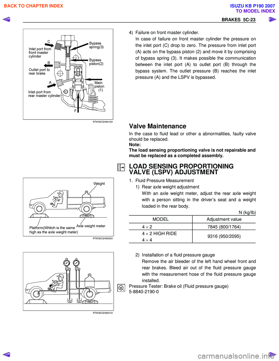
4) Failure on front master cylinder.
In case of failure on front master cylinder the pressure on the inlet port (C) drop to zero. The pressure from inlet port
(A) acts on the bypass piston (2) and move it by comprising
of bypass spring (3). It makes possible the communication
between the inlet port (A) to outlet port (B) through the
bypass system. The outlet pressure (B) reaches the inlet
pressure (A) and the LSPV is bypassed.
Valve Maintenance
In the case to fluid lead or other a abnormalities, faulty valve
should be replaced.
Note:
The load sensing proportioning valve is not repairable and
must be replaced as a completed assembly.
LOAD SENSING PROPORTIONING
VALVE (LSPV) ADJUSTMENT
RTW 35CSH000301
1. Fluid Pressure Measurement
1) Rear axle weight adjustment
W ith an axle weight meter, adjust the rear axle weight with a person sitting in the driver’s seat and a weight
loaded in the rear body. N (kg/lb)
MODEL Adjustment value
4 × 2 7845 (800/1764)
4 × 2 HIGH RIDE
4 × 4 9316 (950/2095)
RTW 35CSH000101
2) Installation of a fluid pressure gauge
Remove the air bleeder of the left hand wheel front and rear brakes. Bleed air out of the fluid pressure gauge
with the measurement hose of the fluid pressure gauge
installed.
Pressure Tester: Brake oil (Fluid pressure gauge)
5-8840-2190-0
BACK TO CHAPTER INDEX
TO MODEL INDEX
ISUZU KB P190 2007
Page 809 of 6020
6A – 4 ENGINE MECHANICAL
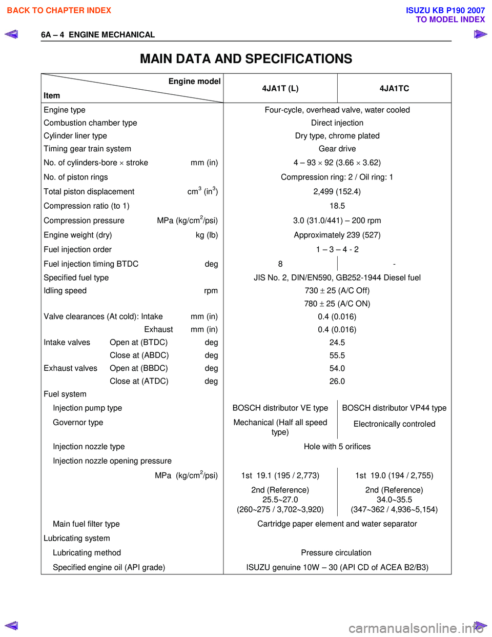
MAIN DATA AND SPECIFICATIONS
Engine model
Item 4JA1T (L)
4JA1TC
Engine type
Combustion chamber type
Cylinder liner type
Timing gear train system Four-cycle, overhead valve, water cooled
Direct injection
Dry type, chrome plated Gear drive
No. of cylinders-bore × stroke mm (in) 4 – 93 × 92 (3.66 × 3.62)
No. of piston rings Compression ring: 2 / Oil ring: 1
Total piston displacement cm3 (in3)
Compression ratio (to 1) 2,499 (152.4)
18.5
Compression pressure MPa (kg/cm2/psi) 3.0 (31.0/441) – 200 rpm
Engine weight (dry) kg (lb)Approximately 239 (527)
Fuel injection order 1 – 3 – 4 - 2
Fuel injection timing BTDC deg8 -
Specified fuel type
Idling speed rpm
Valve clearances (At cold): Intake mm (in)
Exhaust mm (in)
Intake valves Open at (BTDC) deg
Close at (ABDC) deg
Exhaust valves Open at (BBDC) deg
Close at (ATDC) deg
Fuel system JIS No. 2, DIN/EN590, GB252-1944 Diesel fuel
730 ± 25 (A/C Off)
780 ± 25 (A/C ON)
0.4 (0.016)
0.4 (0.016) 24.5
55.5
54.0
26.0
Injection pump type BOSCH distributor VE type BOSCH distributor VP44 type
Governor type Mechanical (Half all speed
type) Electronically controled
Injection nozzle type
Injection nozzle opening pressure Hole with 5 orifices
MPa (kg/cm2/psi) 1st 19.1 (195 / 2,773) 1st 19.0 (194 / 2,755)
2nd (Reference)
25.5 ∼27.0
(260 ∼275 / 3,702 ∼3,920) 2nd (Reference)
34.0 ∼35.5
(347 ∼362 / 4,936 ∼5,154)
Main fuel filter type
Lubricating system
Lubricating method Cartridge paper element and water separator
Pressure circulation
Specified engine oil (API grade) ISUZU genuine 10W – 30 (API CD of ACEA B2/B3)
BACK TO CHAPTER INDEX
TO MODEL INDEX
ISUZU KB P190 2007
Page 811 of 6020
6A – 6 ENGINE MECHANICAL
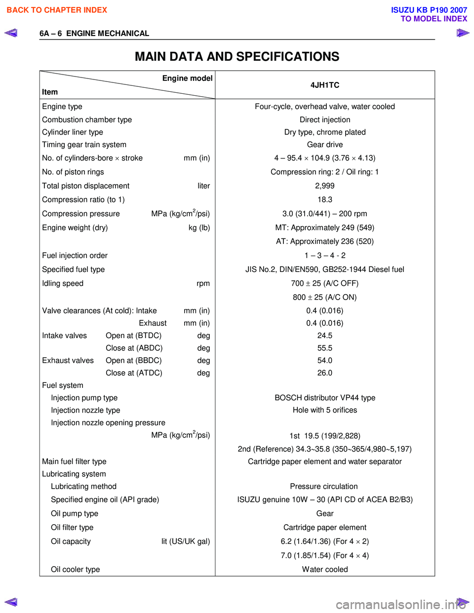
MAIN DATA AND SPECIFICATIONS
Engine model
Item 4JH1TC
Engine type
Four-cycle, overhead valve, water cooled
Combustion chamber type Direct injection
Cylinder liner type
Timing gear train system Dry type, chrome plated
Gear drive
No. of cylinders-bore × stroke mm (in) 4 – 95.4 × 104.9 (3.76 × 4.13)
No. of piston rings Compression ring: 2 / Oil ring: 1
Total piston displacement liter
Compression ratio (to 1) 2,999
18.3
Compression pressure MPa (kg/cm2/psi) 3.0 (31.0/441) – 200 rpm
Engine weight (dry) kg (lb)MT: Approximately 249 (549)
AT: Approximately 236 (520)
Fuel injection order 1 – 3 – 4 - 2
Specified fuel type JIS No.2, DIN/EN590, GB252-1944 Diesel fuel
Idling speed rpm
700 ± 25 (A/C OFF)
800 ± 25 (A/C ON)
Valve clearances (At cold): Intake mm (in)
Exhaust mm (in)
Intake valves Open at (BTDC) deg
Close at (ABDC) deg
Exhaust valves Open at (BBDC) deg
Close at (ATDC) deg
Fuel system
Injection pump type 0.4 (0.016)
0.4 (0.016) 24.5
55.5
54.0
26.0
BOSCH distributor VP44 type
Injection nozzle type
Injection nozzle opening pressure
MPa (kg/cm
2/psi) Hole with 5 orifices
1st 19.5 (199/2,828)
2nd (Reference) 34.3 ∼35.8 (350 ∼365/4,980 ∼5,197)
Main fuel filter type
Lubricating system
Lubricating method Cartridge paper element and water separator
Pressure circulation
Specified engine oil (API grade) ISUZU genuine 10W – 30 (API CD of ACEA B2/B3)
Oil pump type
Oil filter type Gear
Cartridge paper element
Oil capacity lit (US/UK gal)
6.2 (1.64/1.36) (For 4
× 2)
7.0 (1.85/1.54) (For 4 × 4)
Oil cooler type W ater cooled
BACK TO CHAPTER INDEX
TO MODEL INDEX
ISUZU KB P190 2007
Page 947 of 6020
ENGINE COOLING 6B – 3
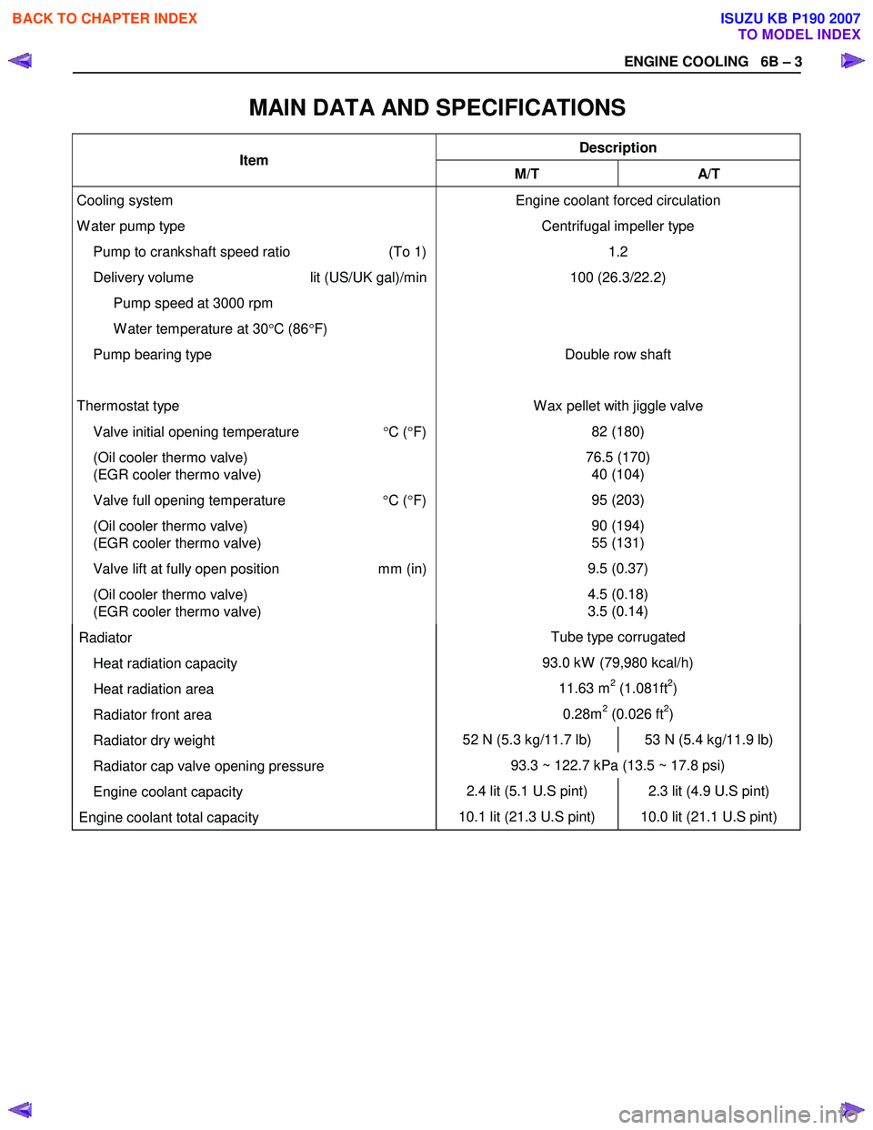
MAIN DATA AND SPECIFICATIONS
Description Item M/T A/T
Cooling system
W ater pump type
Pump to crankshaft speed ratio (To 1)
Delivery volume lit (US/UK gal)/min
Pump speed at 3000 rpm
W ater temperature at 30 °C (86 °F)
Pump bearing type
Thermostat type
Valve initial opening temperature °C ( °F)
(Oil cooler thermo valve)
(EGR cooler thermo valve)
Valve full opening temperature °C ( °F)
(Oil cooler thermo valve)
(EGR cooler thermo valve)
Valve lift at fully open position mm (in)
(Oil cooler thermo valve)
(EGR cooler thermo valve) Engine coolant forced circulation
Centrifugal impeller type 1.2
100 (26.3/22.2)
Double row shaft
W ax pellet with jiggle valve 82 (180)
76.5 (170) 40 (104)
95 (203)
90 (194)
55 (131)
9.5 (0.37)
4.5 (0.18)
3.5 (0.14)
Radiator Tube type corrugated
Heat radiation capacity 93.0 kW (79,980 kcal/h)
Heat radiation area 11.63 m2 (1.081ft2)
Radiator front area 0.28m2 (0.026 ft2)
Radiator dry weight 52 N (5.3 kg/11.7 lb) 53 N (5.4 kg/11.9 lb)
Radiator cap valve opening pressure 93.3 ~ 122.7 kPa (13.5 ~ 17.8 psi)
Engine coolant capacity 2.4 lit (5.1 U.S pint) 2.3 lit (4.9 U.S pint)
Engine coolant total capacity 10.1 lit (21.3 U.S pint) 10.0 lit (21.1 U.S pint)
BACK TO CHAPTER INDEX
TO MODEL INDEX
ISUZU KB P190 2007
Page 970 of 6020
6C – 6 FUEL SYSTEM
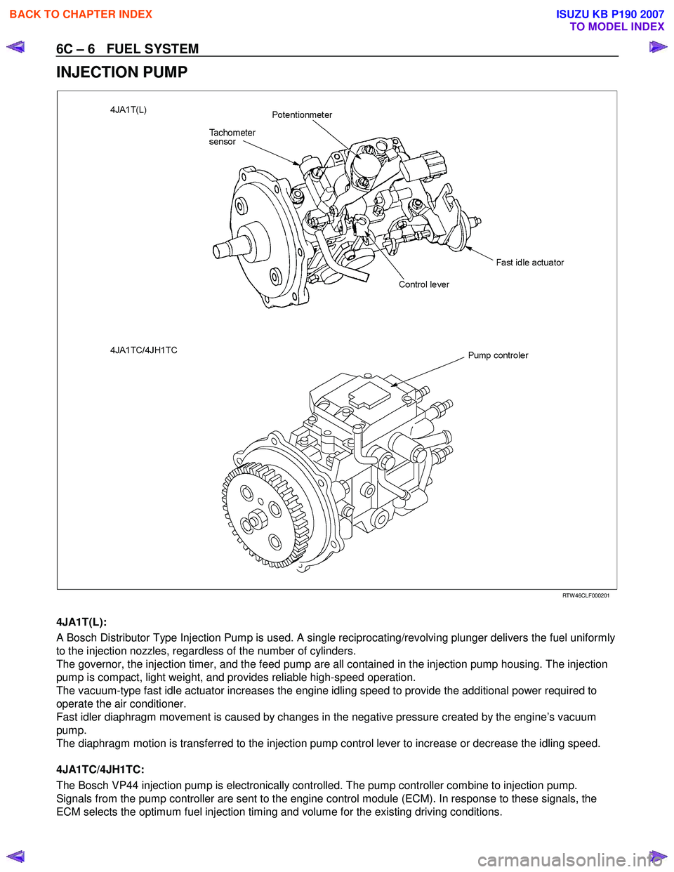
INJECTION PUMP
RTW 46CLF000201
4JA1T(L):
A Bosch Distributor Type Injection Pump is used. A single reciprocating/revolving plunger delivers the fuel uniformly
to the injection nozzles, regardless of the number of cylinders.
The governor, the injection timer, and the feed pump are all contained in the injection pump housing. The injection
pump is compact, light weight, and provides reliable high-speed operation.
The vacuum-type fast idle actuator increases the engine idling speed to provide the additional power required to
operate the air conditioner.
Fast idler diaphragm movement is caused by changes in the negative pressure created by the engine’s vacuum
pump.
The diaphragm motion is transferred to the injection pump control lever to increase or decrease the idling speed.
4JA1TC/4JH1TC:
The Bosch VP44 injection pump is electronically controlled. The pump controller combine to injection pump.
Signals from the pump controller are sent to the engine control module (ECM). In response to these signals, the
ECM selects the optimum fuel injection timing and volume for the existing driving conditions.
BACK TO CHAPTER INDEX
TO MODEL INDEX
ISUZU KB P190 2007
Page 1003 of 6020
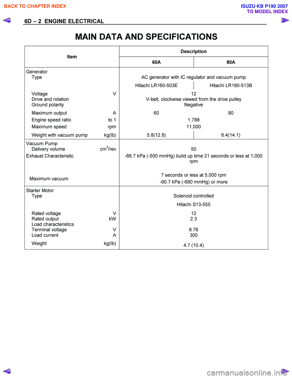
6D – 2 ENGINE ELECTRICAL
MAIN DATA AND SPECIFICATIONS
Description
Item
60A 80A
Generator
Type
AC generator with IC regulator and vacuum pump
Hitachi LR160-503E Hitachi LR180-513B
Voltage V
Drive and rotation
Ground polarity 12
V-belt, clockwise viewed from the drive pulley Negative
Maximum output A 60 80
Engine speed ratio to 1 1.788
Maximum speed rpm 11,000
Weight with vacuum pump kg(lb) 5.8(12.8) 6.4(14.1)
Vacuum Pump
Delivery volume cm3/rev
Exhaust Characteristic
Maximum vacuum
50
-66.7 kPa (-500 mmHg) bulid up time 21 seconds or less at 1,000 rpm
7 seconds or less at 5,000 rpm
-90.7 kPa (-680 mmHg) or more
Starter Motor
Type
Solenoid controlled
Hitachi S13-555
12
2.3
8.76 300 Rated voltage V
Rated output kW
Load characteristics
Terminal voltage V
Load current A
Weight kg(Ib) 4.7 (10.4)
BACK TO CHAPTER INDEX
TO MODEL INDEX
ISUZU KB P190 2007