engine remove ISUZU TF SERIES 2004 Workshop Manual
[x] Cancel search | Manufacturer: ISUZU, Model Year: 2004, Model line: TF SERIES, Model: ISUZU TF SERIES 2004Pages: 4264, PDF Size: 72.63 MB
Page 1776 of 4264

6E–404 4JA1/4JH1 ENGINE DRIVEABILITY AND EMISSIONS
20 Substitute a known good MAF & IAT sensor assembly
and recheck.
Was the problem solved?—Go to Step 21Go to Step 31
21 Replace the MAF & IAT sensor assembly.
Is the action complete?—Veri fy repai r—
22 1. Using the Tech 2, ignition “On” and engine “Off”.
2. Monitor the “Pedal/Throttle Position” and “Idle
Switch” in the data display.
Does the Tech 2 indicate correct “Pedal/Throttle
Position” from 0% to 100% and correct “Idle Switch”
status depending on accelerator pedal operation?—Go to Step 27Go to Step 23
23 1. Using the Tech 2, ignition “On” and engine “Off”.
2. Monitor the “Pedal/Throttle Position” and “Idle
Switch” in the data display.
3. Adjust the accelerator cable or TPS within 0% to
100%.
Was the problem solved?—Verify repair Go to Step 24
24 Check the TPS harness for the following conditions.
Check for poor connector connection.
Check for misrouted harness.
Check for any accessory parts which may cause
electric interference.
If a problem is found, repair as necessary.
Was a problem found? —Verify repair Go to Step 25
25 Substitute a known good TPS and recheck.
Was the problem solved?—Go to Step 26Go to Step 31
26 Replace the TPS.
Is the action complete?—Veri fy repai r—
27 Remove the injection nozzles from the engine and
check for the following conditions.
Improper splay condition.
Operating pressure is incorrect.
If a problem is found, repair as necessary.
Was the problem found?
—Replace the
injection nozzle
and verify repair Go to Step 28 Step Action Value(s) Yes No
1st Stage 2nd Sta ge
4JA1-TCApproximatly
19.0 MpaApprox ima tly
33.5 Mpa
4JH1-TCApproximatly
19.5 MpaApprox ima tly
33.8 Mpa
Page 1779 of 4264

4JA1/4JH1 ENGINE DRIVEABILITY AND EMISSIONS 6E–407
EXCESSIVE WHITE SMOKE
Step Action Value(s) Yes No
1Was the “On-Board Diagnostic (OBD) System Check”
performed?
—Go to Step 2Go to On Board
Diagnostic
(OBD) System
Check
2 1. Perform a bulletin search.
2. If a bulletin that addresses the symptom is found,
correct the condition as instructed in the bulletin.
Was a bulletin found that addresses the symptom?—Verify repair Go to Step 3
3 Was a visually/physical check performed?
—Go to Step 4Go to Visual /
physical Check
4 Is the customer using the incorrect fuel type? Diesel fuel
onlyReplace with
diesel fuel Go to Step 5
5 Check the engine coolant consumption to verify that it
leaks to combustion chamber or ex haust through the
gasket.
Was a problem found?—Verify repair Go to Step 6
6 Check the ECM & PSG grounds to verify that they are
clean and tight. Refer to the ECM wiring diagrams.
Was a problem found?—Verify repair Go to Step 7
7 1. Using the Tech 2, display the ECT sensor and IAT
sensor value.
2. Check the displayed value.
Does the Tech 2 indicate correct temperature
depending on engine condition?
If a problem is found, repair as necessary.
Was the problem found?—Verify repair Go to Step 8
8 1. Using the Tech 2, display the FT sensor value.
2. Check the displayed value.
Does the Tech 2 indicate correct temperature
depending on engine condition?
If a problem is found, repair as necessary.
Was the problem found?—Go to Step 30Go to Step 9
9 1. Using the Tech 2, ignition “On” and engine “Run”.
2. Monitor the “Mass Air Flow” in the data display.
Does the Tech 2 indicate correct “Mass Air Flow”
depending on accelerator pedal operation? —Go to Step 14Go to Step 10
10 Remove the MAF & IAT sensor assembly and check
for the following conditions.
Objects blocking at the MAF sensor element.
If a problem is found, repair as necessary.
Was the problem found?—Verify repair Go to Step 11
11 Check the MAF sensor harness for the following
conditions.
Check for poor connector connection.
Check for misrouted harness.
Check for any accessory parts which may cause
electric interference.
If a problem is found, repair as necessary.
Was a problem found? —Verify repair Go to Step 12
Page 1780 of 4264

6E–408 4JA1/4JH1 ENGINE DRIVEABILITY AND EMISSIONS
12 Substitute a known good MAF & IAT sensor assembly
and recheck.
Was the problem solved?—Go to Step 13Go to Step 30
13 Replace the MAF & IAT sensor assembly.
Is the action complete?—Veri fy repai r—
14 1. Using the Tech 2, ignition “On” and engine “Run”.
2. Monitor the “Glow Time Relay” in the data display.
Does the Tech 2 indicate correct “Glow Time Relay”
status depending on the time from engine “Run”?
If a problem is found, repair as necessary.
Was the problem found?—Go to Step 30Go to Step 15
15 1. Using the Tech 2, ignition “On” and engine “Run”.
2. Monitor the “Glow Time Relay” in the data display
and then, does the supply voltage correctly supply
to the glow plug?
—Go to Step 16Repair voltage
supply circuit
and verify repair
16 Check the glow plugs for continuity.
If a problem is found, repair as necessary.
Was a problem found?
—Verify repair Go to Step 17
17 Remove the CKP sensor from the flywheel housing
and check for the following conditions.
Objects sticking the CKP sensor.
Objects sticking the CKP sensor pulser.
If a problem is found, repair as necessary.
Was the problem found? —Verify repair Go to Step 18
18 Check the CKP sensor harness for the following
conditions.
Check for poor connector connection.
Check for misrouted harness.
Check for any accessory parts which may cause
electric interference.
If a problem is found, repair as necessary.
Was a problem found? —Verify repair Go to Step 19 Step Action Value(s) Yes No
Page 1782 of 4264

6E–410 4JA1/4JH1 ENGINE DRIVEABILITY AND EMISSIONS
25 Remove the eye bolt with gauze filter from the
injection pump and check for the following conditions.
Objects blocking at the gauze filter. Check for a
condition that causes contaminated fuel, such as
the customer is using an aftermarket fuel filter or
ex tended maintenance interval.
Check for a condition that causes fuel wax ing or
icing, such as the customer is using an incorrect
fuel type in winter season or water mix ed with the
fuel.
If a problem is found, repair as necessary.
Was the problem found?
—Replace the
eye bolt with
gauze filter and
verify repair Go to Step 26
26 Remove the injection nozzles from the engine and
check for the following conditions.
Improper splay condition.
Operating pressure is incorrect.
If a problem is found, repair as necessary.
Was the problem found?
—Replace the
injection nozzle
and verify repair Go to Step 27 Step Action Value(s) Yes No
1st Stage 2nd Sta ge
4JA1-TCApproximatly
19.0 MpaApprox ima tly
33.5 Mpa
4JH1-TCApproximatly
19.5 MpaApprox ima tly
33.8 Mpa
Page 1786 of 4264
6E–414 4JA1/4JH1 ENGINE DRIVEABILITY AND EMISSIONS
10 Remove the MAF & IAT sensor assembly and check
for the following conditions.
Objects blocking at the MAF sensor element.
If a problem is found, repair as necessary.
Was the problem found?—Verify repair Go to Step 11
11 Check the MAF sensor harness for the following
conditions.
Check for poor connector connection.
Check for misrouted harness.
Check for any accessory parts which may cause
electric interference.
If a problem is found, repair as necessary.
Was a problem found? —Verify repair Go to Step 12
12 Substitute a known good MAF & IAT sensor assembly
and recheck.
Was the problem solved?—Go to Step 13Go to Step 21
13 Replace the MAF & IAT sensor assembly.
Is the action complete?—Veri fy repai r—
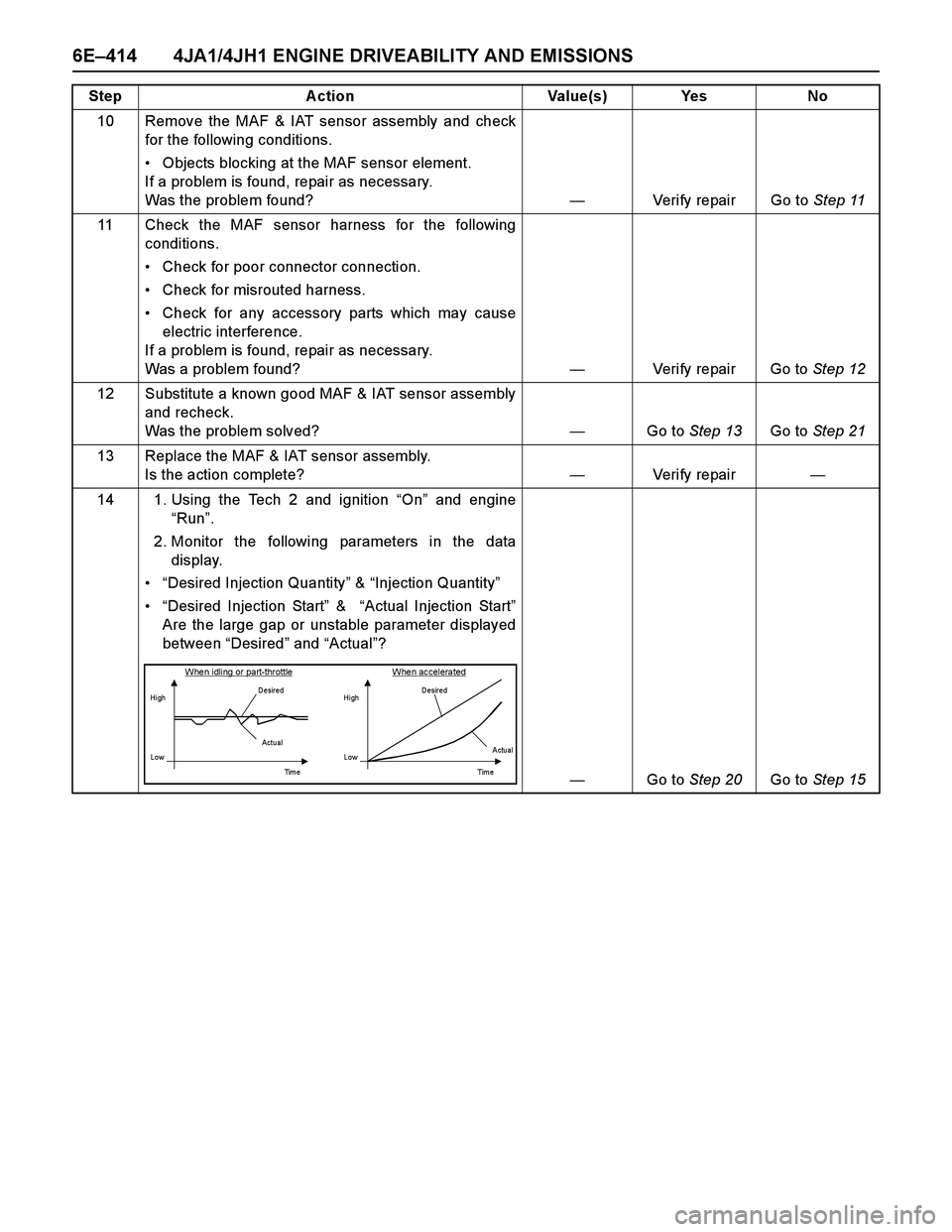
14 1. Using the Tech 2 and ignition “On” and engine
“Run”.
2. Monitor the following parameters in the data
display.
“Desired Injection Quantity” & “Injection Quantity”
“Desired Injection Start” & “Actual Injection Start”
Are the large gap or unstable parameter displayed
between “Desired” and “Actual”?
—Go to Step 20Go to Step 15 Step Action Value(s) Yes No
When idling or part-throttle When accelerated
HighD esired
Low
Ti m e Actu al
High
LowD esired
Actual
Tim e
Page 1788 of 4264
6E–416 4JA1/4JH1 ENGINE DRIVEABILITY AND EMISSIONS
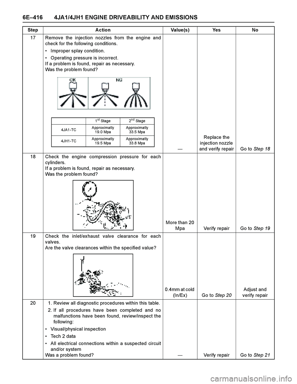
17 Remove the injection nozzles from the engine and
check for the following conditions.
Improper splay condition.
Operating pressure is incorrect.
If a problem is found, repair as necessary.
Was the problem found?
—Replace the
injection nozzle
and verify repair Go to Step 18
18 Check the engine compression pressure for each
cylinders.
If a problem is found, repair as necessary.
Was the problem found?
More than 20
Mpa Verify repair Go to Step 19
19 Check the inlet/ex haust valve clearance for each
valves.
Are the valve clearances within the specified value?
0.4mm at cold
(In/Ex ) Go to Step 20Adjust and
verify repair
20 1. Review all diagnostic procedures within this table.
2. If all procedures have been completed and no
malfunctions have been found, review/inspect the
followi ng:
Visual/physical inspection
Tech 2 data
All electrical connections within a suspected circuit
and/or system
Was a problem found?—Verify repair Go to Step 21 Step Action Value(s) Yes No
1st Stage 2nd Sta ge
4JA1-TCApproximatly
19.0 MpaApprox ima tly
33.5 Mpa
4JH1-TCApproximatly
19.5 MpaApprox ima tly
33.8 Mpa
Page 1790 of 4264
6E–418 4JA1/4JH1 ENGINE DRIVEABILITY AND EMISSIONS
ON-VEHICLE SERVICE PROCEDURE
ENGINE CONTROL MODULE
(ECM)
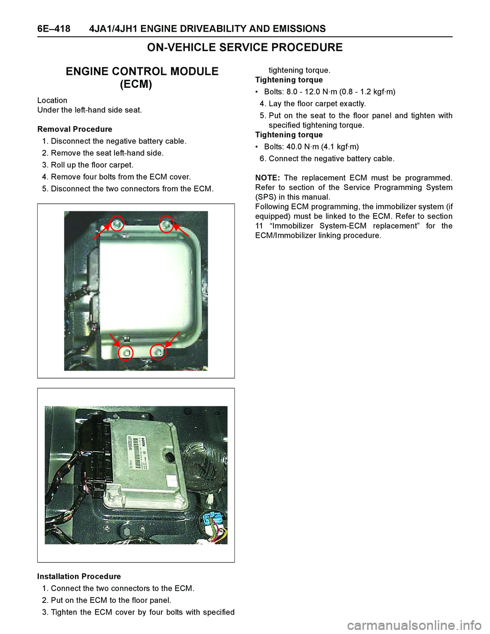
Location
Under the left-hand side seat.
Removal Procedure
1. Disconnect the negative battery cable.
2. Remove the seat left-hand side.
3. Roll up the floor carpet.
4. Remove four bolts from the ECM cover.
5. Disconnect the two connectors from the ECM.
Installation Procedure
1. Connect the two connectors to the ECM.
2. Put on the ECM to the floor panel.
3. Tighten the ECM cover by four bolts with specifiedtightening torque.
Tightening torque
Bolts: 8.0 - 12.0 N·m (0.8 - 1.2 kgf·m)
4. Lay the floor carpet ex actly.
5. Put on the seat to the floor panel and tighten with
specified tightening torque.
Tightening torque
Bolts: 40.0 N·m (4.1 kgf·m)
6. Connect the negative battery cable.
NOTE: The replacement ECM must be programmed.
Refer to section of the Service Programming System
(SPS) in this manual.
Following ECM programming, the immobilizer system (if
equipped) must be linked to the ECM. Refer to section
11 “Immobilizer System-ECM replacement” for the
ECM/Immobilizer linking procedure.
Page 1791 of 4264
4JA1/4JH1 ENGINE DRIVEABILITY AND EMISSIONS 6E–419
CRANKSHAFT POSITION (CKP)
SENSOR
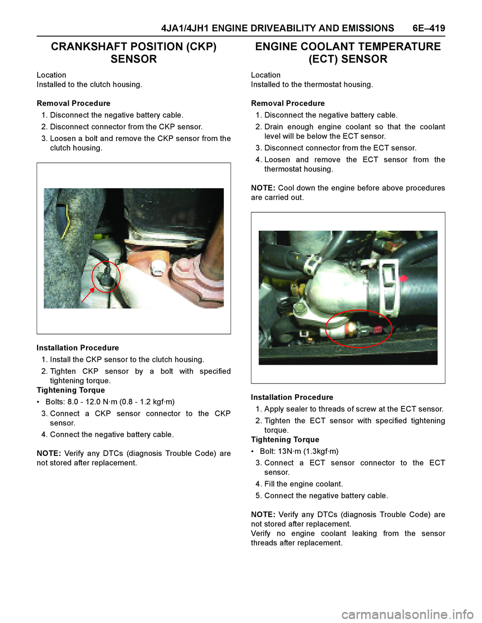
Location
Installed to the clutch housing.
Removal Procedure
1. Disconnect the negative battery cable.
2. Disconnect connector from the CKP sensor.
3. Loosen a bolt and remove the CKP sensor from the
clutch housing.
Installation Procedure
1. Install the CKP sensor to the clutch housing.
2. Tighten CKP sensor by a bolt with specified
tightening torque.
Tightening Torque
Bolts: 8.0 - 12.0 N·m (0.8 - 1.2 kgf·m)
3. Connect a CKP sensor connector to the CKP
sensor.
4. Connect the negative battery cable.
NOTE: Verify any DTCs (diagnosis Trouble Code) are
not stored after replacement.
ENGINE COOLANT TEMPERATURE
(ECT) SENSOR
Location
Installed to the thermostat housing.
Removal Procedure
1. Disconnect the negative battery cable.
2. Drain enough engine coolant so that the coolant
level will be below the ECT sensor.
3. Disconnect connector from the ECT sensor.
4. Loosen and remove the ECT sensor from the
thermostat housing.
NOTE: Cool down the engine before above procedures
are carried out.
Installation Procedure
1. Apply sealer to threads of screw at the ECT sensor.
2. Tighten the ECT sensor with specified tightening
torque.
Tightening Torque
Bolt: 13N·m (1.3kgf·m)
3. Connect a ECT sensor connector to the ECT
sensor.
4. Fill the engine coolant.
5. Connect the negative battery cable.
NOTE: Verify any DTCs (diagnosis Trouble Code) are
not stored after replacement.
Verify no engine coolant leaking from the sensor
threads after replacement.
Page 1792 of 4264
6E–420 4JA1/4JH1 ENGINE DRIVEABILITY AND EMISSIONS
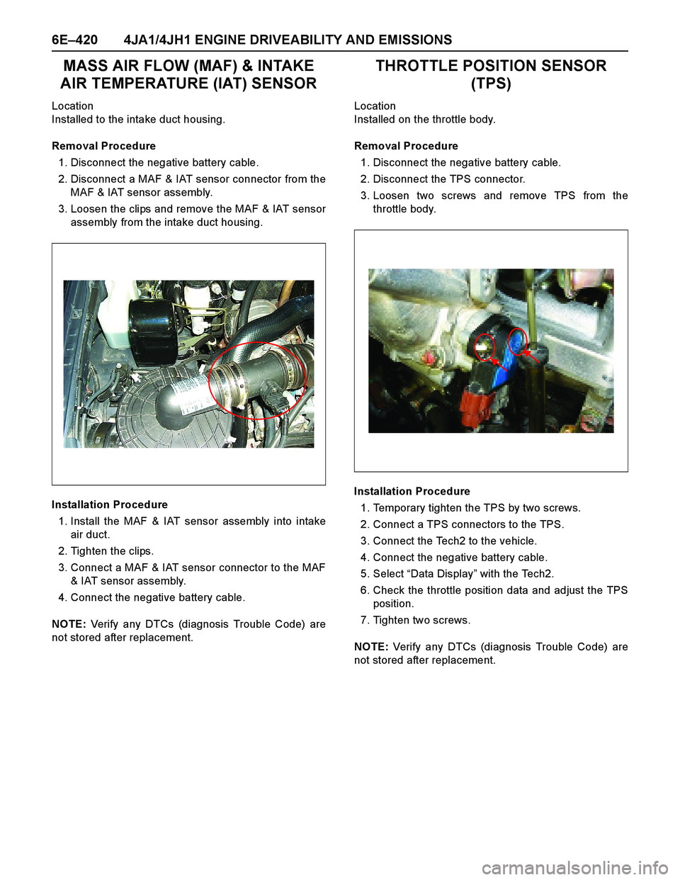
MASS AIR FLOW (MAF) & INTAKE
AIR TEMPERATURE (IAT) SENSOR
Location
Installed to the intake duct housing.
Removal Procedure
1. Disconnect the negative battery cable.
2. Disconnect a MAF & IAT sensor connector from the
MAF & IAT sensor assembly.
3. Loosen the clips and remove the MAF & IAT sensor
assembly from the intake duct housing.
Installation Procedure
1. Install the MAF & IAT sensor assembly into intake
air duct.
2. Tighten the clips.
3. Connect a MAF & IAT sensor connector to the MAF
& IAT sensor assembly.
4. Connect the negative battery cable.
NOTE: Verify any DTCs (diagnosis Trouble Code) are
not stored after replacement.
THROTTLE POSITION SENSOR
(TPS)
Location
Installed on the throttle body.
Removal Procedure
1. Disconnect the negative battery cable.
2. Disconnect the TPS connector.
3. Loosen two screws and remove TPS from the
throttle body.
Installation Procedure
1. Temporary tighten the TPS by two screws.
2. Connect a TPS connectors to the TPS.
3. Connect the Tech2 to the vehicle.
4. Connect the negative battery cable.
5. Select “Data Display” with the Tech2.
6. Check the throttle position data and adjust the TPS
position.
7. Tighten two screws.
NOTE: Verify any DTCs (diagnosis Trouble Code) are
not stored after replacement.
Page 1793 of 4264
4JA1/4JH1 ENGINE DRIVEABILITY AND EMISSIONS 6E–421
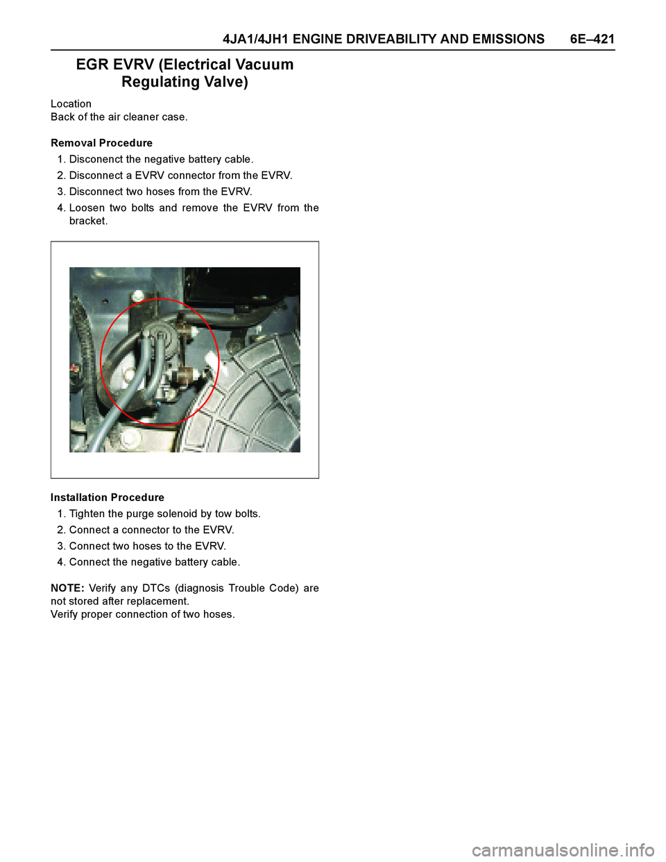
EGR EVRV (Electrical Vacuum
Regulating Valve)
Location
Back of the air cleaner case.
Removal Procedure
1. Disconenct the negative battery cable.
2. Disconnect a EVRV connector from the EVRV.
3. Disconnect two hoses from the EVRV.
4. Loosen two bolts and remove the EVRV from the
bracket.
Installation Procedure
1. Tighten the purge solenoid by tow bolts.
2. Connect a connector to the EVRV.
3. Connect two hoses to the EVRV.
4. Connect the negative battery cable.
NOTE: Verify any DTCs (diagnosis Trouble Code) are
not stored after replacement.
Verify proper connection of two hoses.