engine coolant ISUZU TF SERIES 2004 Workshop Manual
[x] Cancel search | Manufacturer: ISUZU, Model Year: 2004, Model line: TF SERIES, Model: ISUZU TF SERIES 2004Pages: 4264, PDF Size: 72.63 MB
Page 2626 of 4264
6E–50 ENGINE DRIVEABILITY AND EMISSIONS
Crankshaft Position (CKP) Sensor
The crankshaft position (CKP) sensor, which sends a
signal necessary for deciding on injection timing to the
ECM, is mounted on the left-hand side of the cylinder
block just back of the A/C compressor.
The crankshaft has a 58 teeth press-fit timing disc, from
which the CKP sensor reads the position of the
crankshaft at all the times. It converts this to an
electrical signal, which it sends to the ECM.
Using the 58 X signals per rotation and the timing-mark
signal sent by the CKP sensor, the ECM is able to
accurately calculate engine speed and crank position.
The ECM converts the 58 X signals into square signals.
This converted signal is sent from the ECM terminal J2-
25 to the tachometer.
Knock Sensor (KS)
The knock sensor (KS) contains an element that
converts detection of knock into an electrical signal, and
is mounted on cylinder block wall.
When the ECM receives a signal that indicates knock,
the ECM orders ignition timing to be adjusted to
compensate.
Engine Coolant Temperature (ECT) Sensor
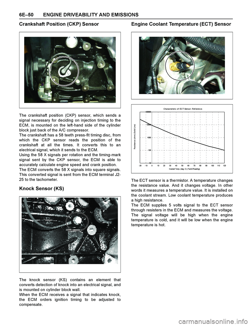
The ECT sensor is a thermistor. A temperature changes
the resistance value. And it changes voltage. In other
words it measures a temperature value. It is installed on
the coolant stream. Low coolant temperature produces
a high resistance.
The ECM supplies 5 volts signal to the ECT sensor
through resisters in the ECM and measures the voltage.
The signal voltage will be high when the engine
temperature is cold, and it will be low when the engine
temperature is hot.
Ch aract erist ic of ECT Sens or -Ref erenc e-
10 100 1000 10000 100000
-20-100 10203040 5060708090100110120
Cool ant Temp. ( deg . C ) ( Tech2 R eadi ng )
Resistance (ohm) (Solid Line)
Page 2628 of 4264
6E–52 ENGINE DRIVEABILITY AND EMISSIONS
GENERAL DESCRIPTION FOR FUEL
METERING
The fuel metering system starts with the fuel in the fuel
tank. An electric fuel pump, located in the fuel tank,
pumps fuel to the fuel rail through an in-line fuel filter.
The pump is designed to provide fuel at a pressure
above the pressure needed by the injectors.
A fuel pressure regulator in the fuel rail keeps fuel
available to the fuel injectors at a constant pressure.
A return line delivers unused fuel back to the fuel tank.
The basic function of the air/fuel metering system is to
control the air/fuel delivery to the engine. Fuel is
delivered to the engine by individual fuel injectors
mounted in the intake manifold.
The main control sensor is the heated ox ygen sensor
located in the ex haust system. The heated ox ygen
sensor reports to the ECM how much oxygen is in the
ex haust gas. The ECM changes the air/fuel ratio to the
engine by controlling the amount of time that fuel
injector is “On”.
The best mix ture to minimize exhaust emissions is 14.7
parts of air to 1 part of gasoline by weight, which allows
the catalytic converter to operate most efficiently.
Because of the constant measuring and adjusting of the
air/fuel ratio, the fuel injection system is called a “closed
loop” system.
The ECM monitors signals from several sensors in
order to determine the fuel needs of the engine. Fuel is
delivered under one of several conditions called “mode”.
All modes are controlled by the ECM.
Battery Voltage Correction Mode
When battery voltage is low, the ECM will compensate
for the weak spark by increasing the following:
The amount of fuel delivered.
The idle RPM.
Clear Flood Mode
Clear a flooded engine by pushing the accelerator pedal
down all the way. The ECM then de-energizes the fuel
injectors. The ECM holds the fuel injectors de-energized
as long as the throttle remains above 75% and the
engine speed is below 800 RPM. If the throttle position
becomes less than 75%, the ECM again begins to pulse
the injectors ON and OFF, allowing fuel into the
cylinders.
Deceleration Fuel Cutoff (DFCO) Mode
The ECM reduces the amount of fuel injected when it
detects a decrease in the throttle position and the air
flow. When deceleration is very fast, the ECM may cut
off fuel completely. Until enable conditions meet the
engine revolution less 1000 rpm or manifold absolute
pressure less than 10 kPa.
Engine Speed/ Vehicle Speed/ Fuel Disable
Mode
The ECM monitors engine speed. It turns off the fuel
injectors when the engine speed increases above 6000
RPM. The fuel injectors are turned back on when
engine speed decreases below 3500 RPM.
Acceleration Mode
The ECM provides ex tra fuel when it detects a rapid
increase in the throttle position and the air flow.
Fuel Cutoff Mode
No fuel is delivered by the fuel injectors when the
ignition is OFF. This prevents engine run-on. In addition,
the ECM suspends fuel delivery if no reference pulses
are detected (engine not running) to prevent engine
flooding.
Starting Mode
When the ignition is first turned ON, the ECM energizes
the fuel pump relay for two seconds to allow the fuel
pump to build up pressure. The ECM then checks the
engine coolant temperature (ECT) sensor and the
throttle position sensor to determine the proper air/fuel
ratio for starting.
The ECM controls the amount of fuel delivered in the
starting mode by adjusting how long the fuel injectors
are energized by pulsing the injectors for very short
times.
Run Mode
The run mode has the following two conditions:
Open loop
Closed loop
When the engine is first started, the system is in “open
loop” operation. In “Open Loop,” the ECM ignores the
signal from the heated oxygen sensor (HO2S). It
calculates the air/fuel ratio based on inputs from the TP,
ECT, and MAP sensors.
The system remains in “Open Loop” until the following
conditions are met:
The HO2S has a varying voltage output showing that
it is hot enough to operate properly (this depends on
temperature).
The ECT has reached a specified temperature.
A specific amount of time has elapsed since starting
the engine.
Engine speed has been greater than a specified RPM
since start-up.
The specific values for the above conditions vary with
different engines and are stored in the programmable
read only memory (PROM). When these conditions are
met, the system enters “closed loop” operation. In
“closed loop,” the ECM calculates the air/fuel ratio
(injector on-time) based on the signal from the HO2S.
This allows the air/fuel ratio to stay very close to 14.7:1.
Page 2629 of 4264
ENGINE DRIVEABILITY AND EMISSIONS 6E–53
Fuel Metering System Components
The fuel metering system is made up of the following
parts.
Fuel injector
Throttle body
Fuel rail
Fuel pressure regulator
ECM
Crankshaft position (CKP) sensor
Idle air control (IAC) valve
Fuel pump
Fuel Injector
The group fuel injection fuel injector is a solenoid
operated device controlled by the ECM. The ECM
energizes the solenoid, which opens a valve to allow
fuel delivery.
The fuel is injected under pressure in a conical spray
pattern at the opening of the intake valve. Ex cess fuel
not used by the injectors passes through the fuel
pressure regulator before being returned to the fuel
tank.
Fuel Pressure Regulator
The fuel pressure regulator is a diaphragm-operated
relief valve mounted on the fuel rail with fuel pump
pressure on one side and manifold pressure on the
other side. The fuel pressure regulator maintains the
fuel pressure available to the injector at three times
barometric pressure adjusted for engine load. It may be
serviced separately.
If the pressure is too low or poor performance, DTC
P0131 or P1171 will be the result. If the pressure is too
high, DTC P0132 or P1167 will be the result. Refer to
Fuel System Diagnosis for information on diagnosing
fuel pressure conditions.
Fuel Rail
The fuel rail is mounted to the top of the engine and
distributes fuel to the individual injectors. Fuel is
delivered to the fuel inlet tube of the fuel rail by the fuel
lines. The fuel goes through the fuel rail to the fuel
pressure regulator. The fuel pressure regulator
maintains a constant fuel pressure at the injectors.
Remaining fuel is then returned to the fuel tank.
Fuel Pump Electrical Circuit
When the key is first turned ON, the ECM energizes the
fuel pump relay for two seconds to build up the fuel
pressure quickly. If the engine is not started within two
seconds, the ECM shuts the fuel pump off and waits
until the engine is cranked. When the engine is cranked
and the 58X crankshaft position signal has been
detected by the ECM, the ECM supplies 12 volts to the
fuel pump relay to energize the electric in-tank fuel
pump.
An inoperative fuel pump will cause a “no-start”
condition. A fuel pump which does not provide enoughpressure will result in poor performance.
Thottle Body Unit
The throttle body has a throttle plate to control the
amount of air delivered to the engine. The Thottle
position sensor and IAC valve are also mounted on the
throttle body.
Vacuum ports located behind the throttle plate provide
the vacuum signals needed by various components.
Engine coolant is directed through a coolant cavity in
the throttle body to warm the throttle valve and to
prevent icing.
Page 2630 of 4264
6E–54 ENGINE DRIVEABILITY AND EMISSIONS
GENERAL DESCRIPTION FOR ELECTRIC
IGNITION SYSTEM
The engine use two ignition coils, one per two cylinders.
A two wire connector provides a battery voltage primary
supply through the ignition fuse.
The ignition control spark timing is the ECM’s method of
controlling the spark advance and the ignition dwell.
The ignition control spark advance and the ignition dwell
are calculated by the ECM using the following inputs.
Engine speed
Crankshaft position (CKP) sensor
Engine coolant temperature (ECT) sensor
Throttle position sensor
Vehicle speed sensor
ECM and ignition system supply voltage
Ignition coil works to generate only the secondary
voltage be receiving the primary voltage from ECM.
The primary voltage is generated at the coil driver
located in the ECM. The coil driver generate the primary
voltage based on the crankshaft position signal. In
accordance with the crankshaft position signal, ignition
coil driver determines the adequate ignition timing and
also cylinder number to ignite.
Ignition timing is determined the coolant temperature,
intake air temperature, engine speed, engine load,
knock sensor signal, etc.
Spark Plug
Although worn or dirty spark plugs may give satisfactory
operation at idling speed, they frequently fail at higher
engine speeds. Faulty spark plugs may cause poor fuel
economy, power loss, loss of speed, hard starting and
generally poor engine performance. Follow the
scheduled maintenance service recommendations to
ensure satisfactory spark plug performance. Refer to
Maintenance and Lubrication.
Normal spark plug operation will result in brown to
grayish-tan deposits appearing on the insulator portion
of the spark plug. A small amount of red-brown, yellow,
and white powdery material may also be present on the
insulator tip around the center electrode. These
deposits are normal combustion by-products of fuels
and lubricating oils with additives. Some electrode wear
will also occur. Engines which are not running properly
are often referred to as “misfiring.” This means the
ignition spark is not igniting the air/fuel mix ture at the
proper time. While other ignition and fuel system causes
must also be considered, possible causes include
ignition system conditions which allow the spark voltage
to reach ground in some other manner than by jumping
across the air gap at the tip of the spark plug, leaving
the air/fuel mix ture unburned. Misfiring may also occur
when the tip of the spark plug becomes overheated and
ignites the mixture before the spark jumps. This is
referred to as “pre-ignition.”
Spark plugs may also misfire due to fouling, ex cessive
gap, or a cracked or broken insulator. If misfiring occursbefore the recommended replacement interval, locate
and correct the cause.
Carbon fouling of the spark plug is indicated by dry,
black carbon (soot) deposits on the portion of the spark
plug in the cylinder. Ex cessive idling and slow speeds
under light engine loads can keep the spark plug
temperatures so low that these deposits are not burned
off. Very rich fuel mix tures or poor ignition system output
may also be the cause. Refer to DTC P1167.
Oil fouling of the spark plug is indicated by wet oily
deposits on the portion of the spark plug in the cylinder,
usually with little electrode wear. This may be caused by
oil during break-in of new or newly overhauled engines.
Deposit fouling of the spark plug occurs when the
normal red-brown, yellow or white deposits of
combustion by-products become sufficient to cause
misfiring. In some cases, these deposits may melt and
form a shiny glaze on the insulator around the center
electrode. If the fouling is found in only one or two
cylinders, valve stem clearances or intake valve seals
may be allowing ex cess lubricating oil to enter the
cylinder, particularly if the deposits are heavier on the
side of the spark plug facing the intake valve.
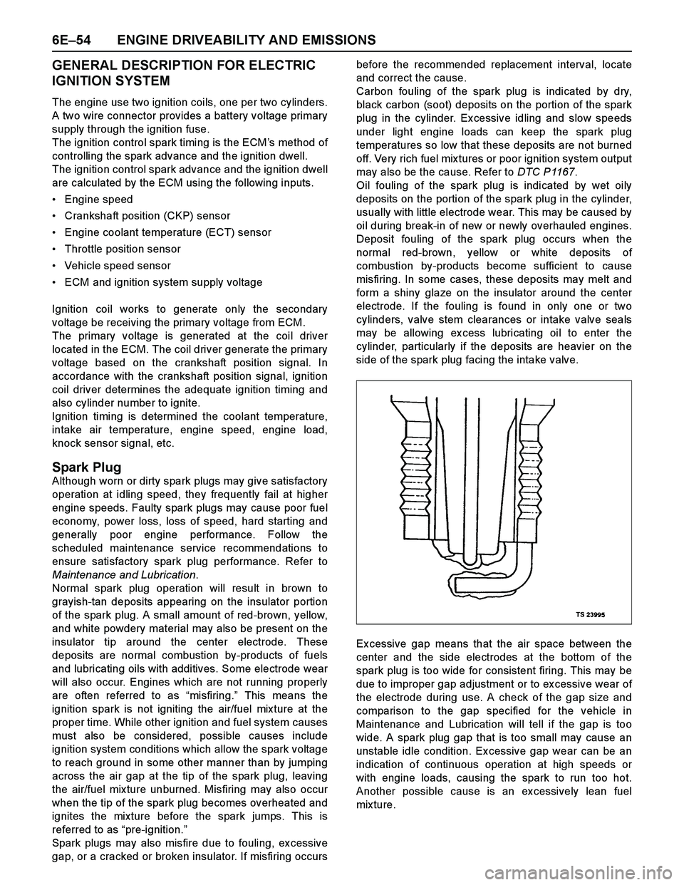
Ex cessive gap means that the air space between the
center and the side electrodes at the bottom of the
spark plug is too wide for consistent firing. This may be
due to improper gap adjustment or to ex cessive wear of
the electrode during use. A check of the gap size and
comparison to the gap specified for the vehicle in
Maintenance and Lubrication will tell if the gap is too
wide. A spark plug gap that is too small may cause an
unstable idle condition. Ex cessive gap wear can be an
indication of continuous operation at high speeds or
with engine loads, causing the spark to run too hot.
Another possible cause is an ex cessively lean fuel
mixture.
Page 2633 of 4264
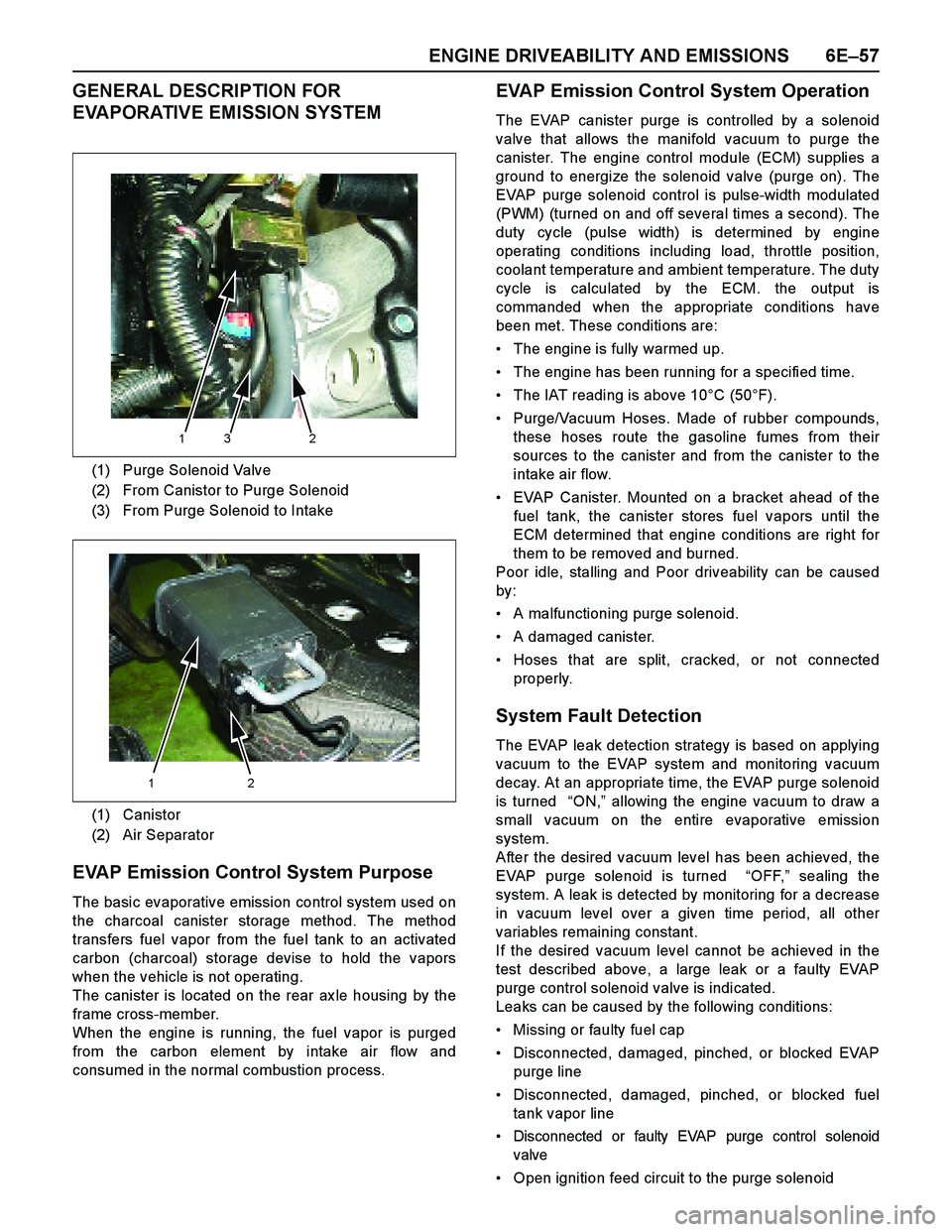
ENGINE DRIVEABILITY AND EMISSIONS 6E–57
GENERAL DESCRIPTION FOR
EVAPORATIVE EMISSION SYSTEM
EVAP Emission Control System Purpose
The basic evaporative emission control system used on
the charcoal canister storage method. The method
transfers fuel vapor from the fuel tank to an activated
carbon (charcoal) storage devise to hold the vapors
when the vehicle is not operating.
The canister is located on the rear ax le housing by the
frame cross-member.
When the engine is running, the fuel vapor is purged
from the carbon element by intake air flow and
consumed in the normal combustion process.
EVAP Emission Control System Operation
The EVAP canister purge is controlled by a solenoid
valve that allows the manifold vacuum to purge the
canister. The engine control module (ECM) supplies a
ground to energize the solenoid valve (purge on). The
EVAP purge solenoid control is pulse-width modulated
(PWM) (turned on and off several times a second). The
duty cycle (pulse width) is determined by engine
operating conditions including load, throttle position,
coolant temperature and ambient temperature. The duty
cycle is calculated by the ECM. the output is
commanded when the appropriate conditions have
been met. These conditions are:
The engine is fully warmed up.
The engine has been running for a specified time.
The IAT reading is above 10°C (50°F).
Purge/Vacuum Hoses. Made of rubber compounds,
these hoses route the gasoline fumes from their
sources to the canister and from the canister to the
intake air flow.
EVAP Canister. Mounted on a bracket ahead of the
fuel tank, the canister stores fuel vapors until the
ECM determined that engine conditions are right for
them to be removed and burned.
Poor idle, stalling and Poor driveability can be caused
by:
A malfunctioning purge solenoid.
A damaged canister.
Hoses that are split, cracked, or not connected
properly.
System Fault Detection
The EVAP leak detection strategy is based on applying
vacuum to the EVAP system and monitoring vacuum
decay. At an appropriate time, the EVAP purge solenoid
is turned “ON,” allowing the engine vacuum to draw a
small vacuum on the entire evaporative emission
system.
After the desired vacuum level has been achieved, the
EVAP purge solenoid is turned “OFF,” sealing the
system. A leak is detected by monitoring for a decrease
in vacuum level over a given time period, all other
variables remaining constant.
If the desired vacuum level cannot be achieved in the
test described above, a large leak or a faulty EVAP
purge control solenoid valve is indicated.
Leaks can be caused by the following conditions:
Missing or faulty fuel cap
Disconnected, damaged, pinched, or blocked EVAP
purge line
Disconnected, damaged, pinched, or blocked fuel
tank vapor line
Disconnected or faulty EVAP purge control solenoid
valve
Open ignition feed circuit to the purge solenoid (1) Purge Solenoid Valve
(2) From Canistor to Purge Solenoid
(3) From Purge Solenoid to Intake
(1) Canistor
(2) Air Separator
132
12
Page 2634 of 4264
6E–58 ENGINE DRIVEABILITY AND EMISSIONS
Damaged EVAP canister
Leaking fuel sender assembly O-ring
Leaking fuel tank or fuel filler neck
The ECM supplies a ground to energize the purge
control solenoid valve (purge “ON” ). The EVAP purge
control is turned “ON” and “OFF,” several times a
second. The duty cycle (pulse width) is determined by
engine operating conditions including load, throttle
position, coolant temperature and ambient temperature.
The duty cycle is calculated by the ECM and the output
is commanded when the appropriate conditions have
been met.
The system checks for conditions that cause the EVAP
system to purge continuously by commanding the EVAP
purge solenoid “OFF”, EVAP purge solenoid duty ratio
“0%”. If fuel tank vacuum level increases during the test,
a continuous purge flow condition is indicated. This can
be caused by the following conditions:
EVAP purge solenoid leaking
EVAP purge and engine vacuum lines switched at the
EVAP purge control solenoid valve
EVAP purge control solenoid valve driver circuit
grounded
Page 2648 of 4264
6E–72 ENGINE DRIVEABILITY AND EMISSIONS
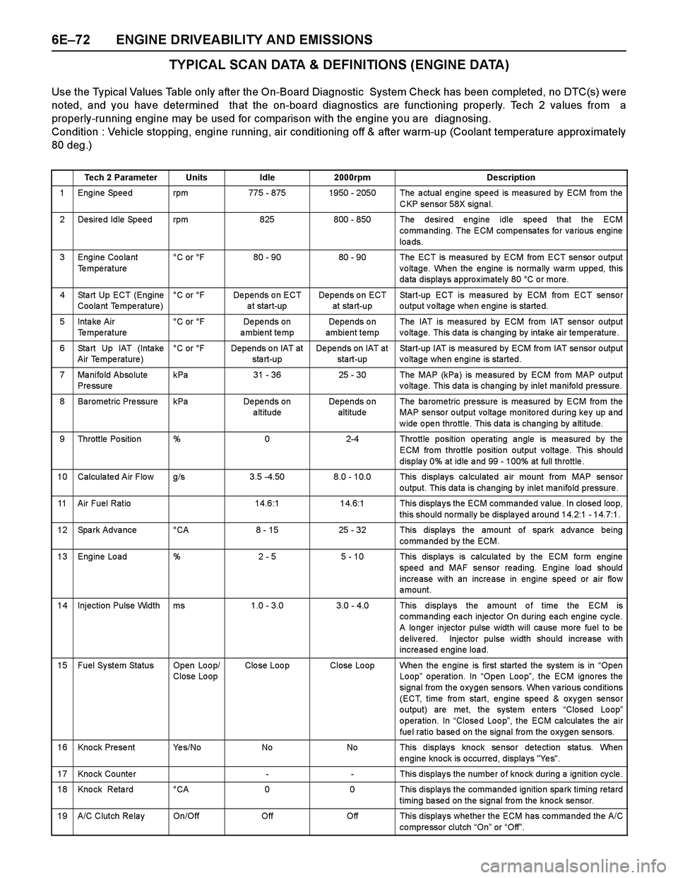
TYPICAL SCAN DATA & DEFINITIONS (ENGINE DATA)
Use the Typical Values Table only after the On-Board Diagnostic System Check has been completed, no DTC(s) were
noted, and you have determined that the on-board diagnostics are functioning properly. Tech 2 values from a
properly-running engine may be used for comparison with the engine you are diagnosing.
Condition : Vehicle stopping, engine running, air conditioning off & after warm-up (Coolant temperature approx imately
80 deg.)
Tech 2 ParameterUnitsIdle2000rpmDescription
1 Engine Speed rpm775 - 8751950 - 2050 The actual engine speed is measured by ECM from the
CKP sensor 58X signal.
2 Desired Idle Speed rpm825800 - 850 The desired engine idle speed that the ECM
commanding. The ECM compensates for various engine
loa ds.
3 Engine Coolant
Te mpe rature°C or °F80 - 9080 - 90 The ECT is measured by ECM from ECT sensor output
voltage. When the engine is normally warm upped, this
data displays approximately 80 °C or more.
4 Sta rt Up ECT (Engine
Coolant Temperature)°C or °FDepends on ECT
a t start-upDepends on ECT
at sta rt-upStart-up ECT is measured by ECM from ECT sensor
output voltage when engine is started.
5Inta ke Air
Temperature °C or °FDe pe nds on
ambient tempDepends on
ambient tempThe IAT is mea sure d by ECM from IAT sensor o utput
voltage. This data is changing by intake air temperature.
6 Sta rt Up IAT (Inta ke
Air Temperature)°C or °FDepends on IAT at
sta rt-upDepends on IAT at
start-upStart-up IAT is me asured by ECM fro m IAT se nso r o utput
voltage when engine is started.
7 Manifold Absolute
Pre ssurekPa31 - 3625 - 30The MAP (kPa ) is me asure d by ECM fro m MAP o utput
voltage. This data is changing by inlet manifold pressure.
8 Barometric Pressure kPaDe pe nds on
altitudeDepends on
altitudeThe ba rome tric pre ssure is me asured by ECM fro m the
MAP sensor output voltage monitored during key up and
w ide o pe n thro ttle. This data is cha nging by a ltitude.
9 Throttle Position %02-4 Throttle position operating angle is measured by the
ECM from throttle position output voltage. This should
displa y 0% at idle a nd 99 - 100% at full throttle .
10 Calculated Air Flow g/s3.5 -4.508.0 - 10.0 This displays calculated air mount from MAP sensor
output. This data is changing by inlet manifold pressure .
11 Air Fuel Ratio14.6:114.6:1 This displays the ECM commanded value. In closed loop,
this should normally be displayed around 14.2:1 - 14.7:1.
12 Spark Advance °CA8 - 1525 - 32 This displays the amount of spark advance being
commanded by the ECM.
13 Engine Load %2 - 55 - 10 This displays is calculated by the ECM form engine
speed and MAF sensor reading. Engine load should
incre ase with an incre ase in engine spe ed or air flo w
amount.
14 Injection Pulse Width ms1.0 - 3.0 3.0 - 4.0 This displays the amount of time the ECM is
commanding each injector On during each engine cycle.
A lo nger injecto r pulse width will ca use more fuel to be
delivered. Injector pulse width should increase with
increased engine load.
15 Fuel System Status Open Loop/
Close LoopClo se Loo pClose Loop When the engine is first started the system is in “Open
Loop” operation. In “Open Loop”, the ECM ignores the
signal from the oxygen sensors. When various conditions
(ECT, time from start, engine speed & oxygen sensor
o utput) are me t, the syste m e nte rs “Closed Lo op”
o pera tio n. In “Close d Lo o p”, the ECM ca lculate s the air
fuel ratio based on the signal from the oxygen sensors.
16 Knock Present Yes/NoNoNo This displays knock sensor detection status. When
engine knock is occurred, displays "Yes".
17 Knock Counter-- This displays the number of knock during a ignition cycle.
18 Kno ck Reta rd °CA00 This displa ys the commande d ignitio n spa rk timing re tard
timing based on the signal from the knock sensor.
19 A/C Clutch Re la y On/OffOffOff This display s whe the r the ECM has co mma nde d the A/C
co mpre ssor clutch “On” or “Off”.
Page 2650 of 4264
6E–74 ENGINE DRIVEABILITY AND EMISSIONS
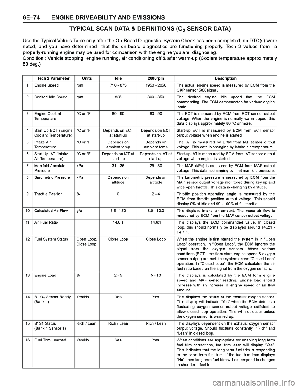
TYPICAL SCAN DATA & DEFINITIONS (O2 SENSOR DATA)
Use the Typical Values Table only after the On-Board Diagnostic System Check has been completed, no DTC(s) were
noted, and you have determined that the on-board diagnostics are functioning properly. Tech 2 values from a
properly-running engine may be used for comparison with the engine you are diagnosing.
Condition : Vehicle stopping, engine running, air conditioning off & after warm-up (Coolant temperature approx imately
80 deg.)
Tech 2 ParameterUnitsIdle2000rpmDescription
1 Engine Speed rpm710 - 8751950 - 2050 The actual engine speed is measured by ECM from the
CKP sensor 58X signal.
2 Desired Idle Speed rpm825800 - 850 The desired engine idle speed that the ECM
commanding. The ECM compensates for various engine
loa ds.
3 Engine Coolant
Te mpe rature°C or °F80 - 9080 - 90 The ECT is measured by ECM from ECT sensor output
voltage. When the engine is normally warm upped, this
data displays approximately 80 °C or more.
4 Sta rt Up ECT (Engine
Coolant Temperature)°C or °FDepends on ECT
a t start-upDepends on ECT
at sta rt-upStart-up ECT is measured by ECM from ECT sensor
output voltage when engine is started.
5Inta ke Air
Temperature °C or °FDe pe nds on
ambient tempDepends on
ambient tempThe IAT is me asure d by ECM fro m IAT se nsor output
voltage. This data is changing by intake air temperature.
6 Sta rt Up IAT (Inta ke
Air Temperature)°C or °FDepends on IAT at
sta rt-upDepends on IAT at
start-upStart-up IAT is measured by ECM from IAT sensor output
voltage when engine is started.
7 Manifold Absolute
Pre ssurekPa31 - 3625 - 30The MAP (kPa ) is mea sured by ECM fro m MAP output
voltage. This data is changing by inlet manifold pressure.
8 Barometric Pressure kPaDe pe nds on
altitudeDepends on
altitudeThe ba ro me tric pressure is mea sure d by ECM from the
MAP se nsor o utput v o ltage monitore d during ke y up and
w ide o pe n thro ttle. This data is cha nging by a ltitude.
9 Throttle Position %02 - 4 Throttle position operating angle is measured by the
ECM from throttle position output voltage. This should
displa y 0% at idle a nd 99 - 100% at full throttle .
10 Calculated Air Flow g/s3.5 -4.508.0 - 10.0 This displays intake air amount. The mass air flow is
measured by ECM from the MAF sensor output voltage.
11 Air Fuel Ratio14.6:114.6:1 This displays the ECM commanded value. In closed
loo p, this sho uld no rmally be display ed a ro und 14.2:1 -
14.7:1.
12 Fuel System Status Open Loop/
Close LoopClo se Loo pClose Loop When the engine is first started the system is in “Ope n
Loop” operation. In “Open Loop”, the ECM igno res the
signal from the oxygen sensors. When various
conditions (ECT, time from start, engine speed & oxygen
sensor output) are met, the system enters “Closed Loop”
operation. In “Closed Loop”, the ECM calculates the air
fuel ratio based on the signal from the oxygen sensors.
13 Engine Load %2 - 55 - 10 This displays is calculated by the ECM form engine
speed and MAF sensor reading. Engine load should
increase with an increase in engine speed or air flow
amount.
14B1 O2 Sensor Ready
(Ba nk 1)Ye s / N oYe sYes This displays the status of the exhaust oxygen sensor.
This display will indicate “Ye s” when the ECM detects a
fluctuating oxygen sensor output voltage sufficient to
a llow clo se d loo p o pe ration. This will no t occur unle ss
the oxygen sensor is warmed up.
15B1S1 Status
(Bank 1 Sensor 1)Rich / Le anRich / LeanRich / Lean This displays dependent on the exhaust oxygen sensor
output voltage. Should fluctuate constantly “Rich” and
“Le an” in closed loop.
16 Fuel Trim Learned Yes/NoYe sYes When conditions are appropriate for enabling long term
fue l trim corrections, fue l trim le a rn will display “Ye s”.
This indica te s tha t the lo ng term fue l trim is respo nding
to the short te rm fue l trim. If the fue l trim le an displa y s
“No”, then long term fuel trim will not respond to changes
in short te rm fuel trim.
Page 2652 of 4264
6E–76 ENGINE DRIVEABILITY AND EMISSIONS
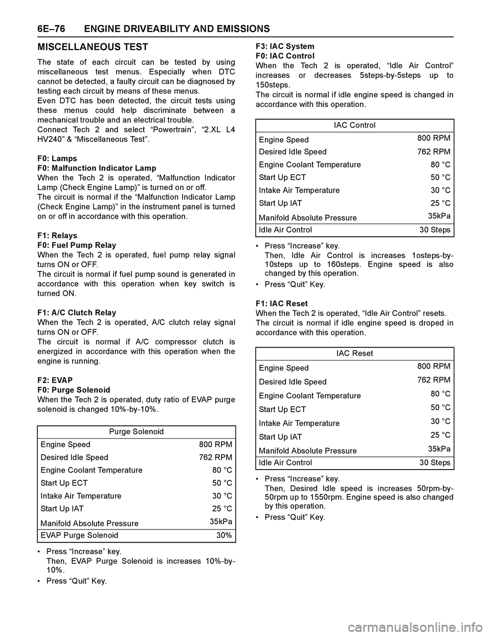
MISCELLANEOUS TEST
The state of each circuit can be tested by using
miscellaneous test menus. Especially when DTC
cannot be detected, a faulty circuit can be diagnosed by
testing each circuit by means of these menus.
Even DTC has been detected, the circuit tests using
these menus could help discriminate between a
mechanical trouble and an electrical trouble.
Connect Tech 2 and select “Powertrain”, “2.XL L4
HV240” & “Miscellaneous Test”.
F0: Lamps
F0: Malfunction Indicator Lamp
When the Tech 2 is operated, “Malfunction Indicator
Lamp (Check Engine Lamp)” is turned on or off.
The circuit is normal if the “Malfunction Indicator Lamp
(Check Engine Lamp)” in the instrument panel is turned
on or off in accordance with this operation.
F1: Relays
F0: Fuel Pump Relay
When the Tech 2 is operated, fuel pump relay signal
turns ON or OFF.
The circuit is normal if fuel pump sound is generated in
accordance with this operation when key switch is
turned ON.
F1: A /C Clutch Relay
When the Tech 2 is operated, A/C clutch relay signal
turns ON or OFF.
The circuit is normal if A/C compressor clutch is
energized in accordance with this operation when the
engine is running.
F2: EVAP
F0: Purge Solenoid
When the Tech 2 is operated, duty ratio of EVAP purge
solenoid is changed 10%-by-10%.
Press “Increase” key.
Then, EVAP Purge Solenoid is increases 10%-by-
10%.
Press “Quit” Key.F3: IAC System
F0: IA C Control
When the Tech 2 is operated, “Idle Air Control”
increases or decreases 5steps-by-5steps up to
150steps.
The circuit is normal if idle engine speed is changed in
accordance with this operation.
Press “Increase” key.
Then, Idle Air Control is increases 1osteps-by-
10steps up to 160steps. Engine speed is also
changed by this operation.
Press “Quit” Key.
F1: IA C Reset
When the Tech 2 is operated, “Idle Air Control” resets.
The circuit is normal if idle engine speed is droped in
accordance with this operation.
Press “Increase” key.
Then, Desired Idle speed is increases 50rpm-by-
50rpm up to 1550rpm. Engine speed is also changed
by this operation.
Press “Quit” Key. Purge Solenoid
Engine Speed 800 RPM
Desired Idle Speed 762 RPM
Engine Coolant Temperature 80 °C
Start Up ECT 50 °C
Intake Air Temperature 30 °C
Start Up IAT 25 °C
Manifold Absolute Pressure 35kPa
EVAP Purge Solenoid 30%
IAC Control
Engine Speed 800 RPM
Desired Idle Speed 762 RPM
Engine Coolant Temperature 80 °C
Start Up ECT 50 °C
Intake Air Temperature 30 °C
Start Up IAT25 °C
Manifold Absolute Pressure 35kPa
Idle Air Control 30 Steps
IAC Reset
Engine Speed 800 RPM
Desired Idle Speed 762 RPM
Engine Coolant Temperature 80 °C
Start Up ECT 50 °C
Intake Air Temperature 30 °C
Start Up IAT 25 °C
Manifold Absolute Pressure 35kPa
Idle Air Control 30 Steps
Page 2653 of 4264
ENGINE DRIVEABILITY AND EMISSIONS 6E–77
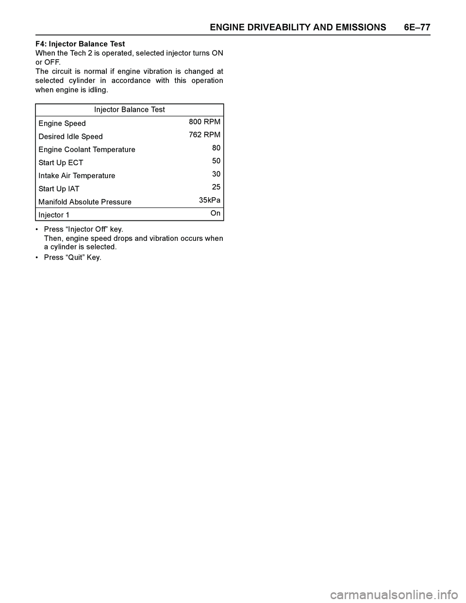
F4: Injector Balance Test
When the Tech 2 is operated, selected injector turns ON
or OFF.
The circuit is normal if engine vibration is changed at
selected cylinder in accordance with this operation
when engine is idling.
Press “Injector Off” key.
Then, engine speed drops and vibration occurs when
a cylinder is selected.
Press “Quit” Key.Injector Balance Test
Engine Speed 800 RPM
Desired Idle Speed 762 RPM
Engine Coolant Temperature 80
Start Up ECT 50
Intake Air Temperature 30
Start Up IAT 25
Manifold Absolute Pressure 35kPa
Injector 1 On