alarm ISUZU TF SERIES 2004 User Guide
[x] Cancel search | Manufacturer: ISUZU, Model Year: 2004, Model line: TF SERIES, Model: ISUZU TF SERIES 2004Pages: 4264, PDF Size: 72.63 MB
Page 3365 of 4264

ANTITHEFT SYSTEM 11B – 19
RTW48AXF024801
0.5
G/Y0.5
G0.5
G
0.5
G/Y2
W
10A
HAZARDEB-16
H-712
28
B-44
B-43 UNLOCK SUPER LOCK
8B-44
24 B-43 LOCK ALARM
TRIGGER
7 B-44
18 B-44 LOCK
151
X-9 3
X-9
4 X-9
2 X-9
HAZARD
RELAY-LHHAZARD
RELAY-RH
HAZARD SW
1
X-10 3
X-10
4 X-10
2 X-10
RR COMBI
LHRR COMBI
RH
B-73 D-241
D-24 D-23 H-102
D-231
D-234
D-232 H-105
H-248
H-108
H-2410
0.5
L/R1.25
L/R 1.25
L/R
1.25
L 0.5
BR/B
27
LOCK
UN LOCK
D-236
D-233
LOCK UN LOCK
KEY
CYLINDER
SW.
DOOR LOCK
ACTUATOR
DRIVER
0.5
B0.5
BFLASHER
CONTROL
ANTI THEFT C/U with SUPER LOCK
WELD
SPLICEB-73 D-261
D-26 D-25 H-132
D-251
D-254
D-252 H-135
H-258
H-138
0.5
L/R1.25
L/R1.25
L 1.25L
1.25L/R
0.5BR/B
1.25L
1.25O
1.25L/R
0.5
BR/B
27
LOCK
UN LOCK
D-256
D-253 H-2510
LOCK UN LOCK
KEY
CYLINDER
SW.
DOOR LOCK
ACTUATOR
PASSENGER
0.5
B0.5
B
WELD
SPLICE 1.25
L/R1.25
L
0.5
BR/B
A
D
E CB
RTW48AXF024801
WIRING DIAGRAM (Super Lock)
Page 3374 of 4264

11B – 28 ANTITHEFT SYSTEM
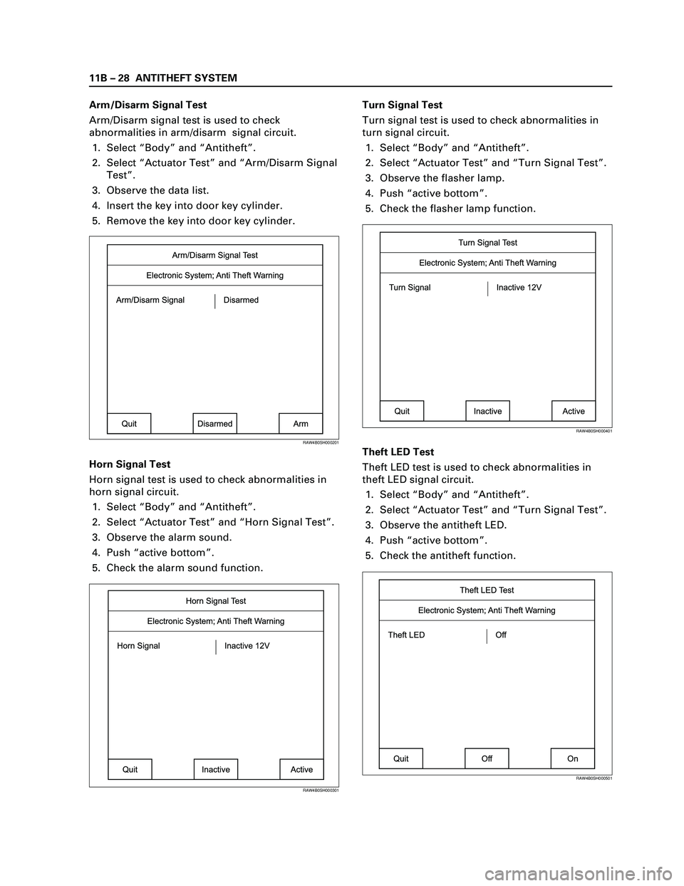
Arm/Disarm Signal Test
Arm/Disarm signal test is used to check
abnormalities in arm/disarm signal circuit.
1. Select “Body” and “Antitheft”.
2. Select “Actuator Test” and “Arm/Disarm Signal
Test”.
3. Observe the data list.
4. Insert the key into door key cylinder.
5. Remove the key into door key cylinder.
Horn Signal Test
Horn signal test is used to check abnormalities in
horn signal circuit.
1. Select “Body” and “Antitheft”.
2. Select “Actuator Test” and “Horn Signal Test”.
3. Observe the alarm sound.
4. Push “active bottom”.
5. Check the alarm sound function.Turn Signal Test
Turn signal test is used to check abnormalities in
turn signal circuit.
1. Select “Body” and “Antitheft”.
2. Select “Actuator Test” and “Turn Signal Test”.
3. Observe the flasher lamp.
4. Push “active bottom”.
5. Check the flasher lamp function.
Theft LED Test
Theft LED test is used to check abnormalities in
theft LED signal circuit.
1. Select “Body” and “Antitheft”.
2. Select “Actuator Test” and “Turn Signal Test”.
3. Observe the antitheft LED.
4. Push “active bottom”.
5. Check the antitheft function.
Arm/Disarm Signal Test
Arm/Disarm Signal DisarmedElectronic System; Anti Theft Warning
Quit
ArmDisarmed
RAW4B0SH000201
Horn Signal Test
Horn Signal Inactive 12VElectronic System; Anti Theft Warning
Quit
ActiveInactive
RAW4B0SH000301
Turn Signal Test
Turn Signal Inactive 12VElectronic System; Anti Theft Warning
Quit
ActiveInactive
RAW4B0SH000401
Theft LED Test
Theft LED OffElectronic System; Anti Theft Warning
Quit
OnOff
RAW4B0SH000501
Page 3380 of 4264

11B – 34 ANTITHEFT SYSTEM
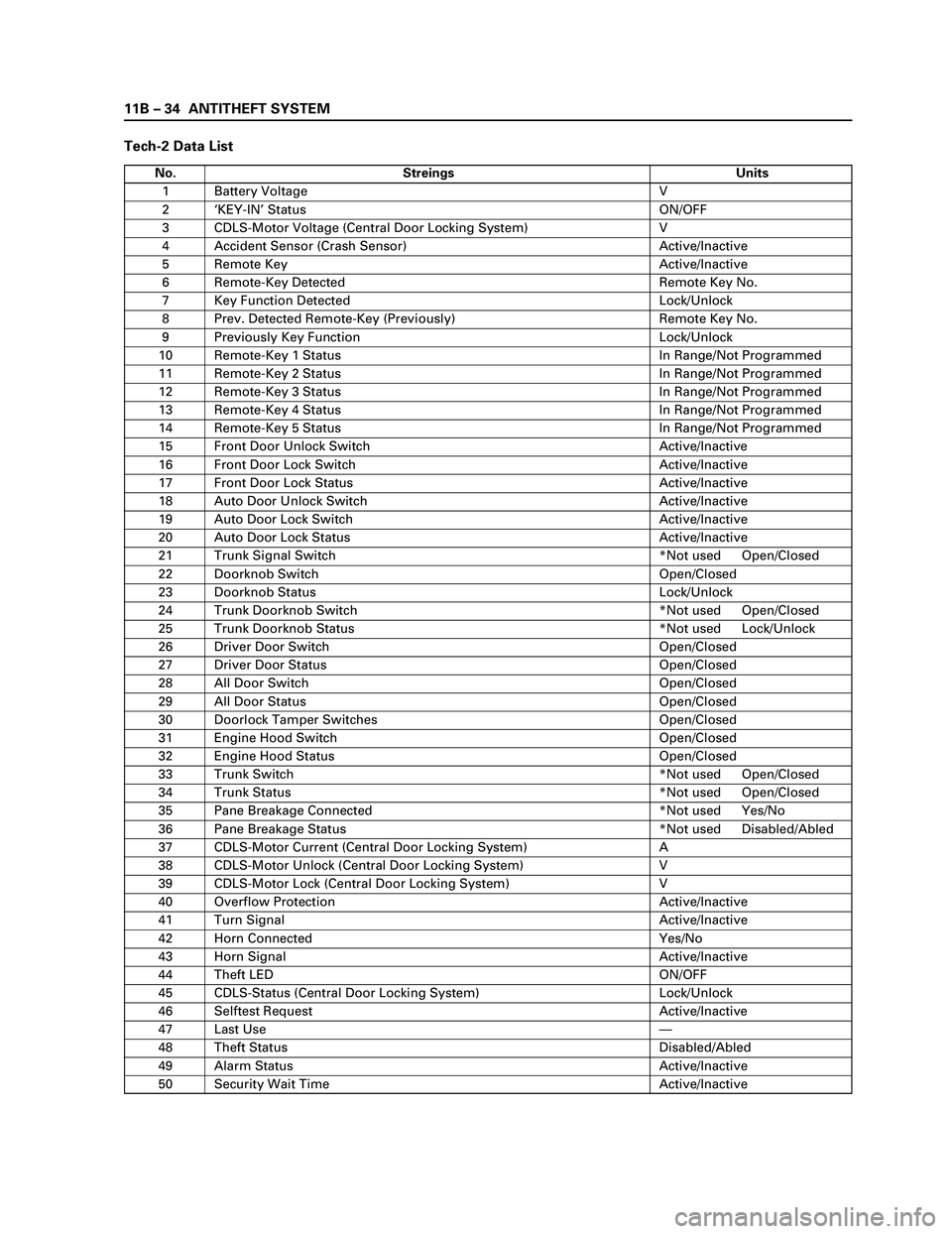
Tech-2 Data List
No. Streings Units
1 Battery Voltage V
2‘KEY-IN’ Status ON/OFF
3 CDLS-Motor Voltage (Central Door Locking System) V
4 Accident Sensor (Crash Sensor) Active/Inactive
5 Remote Key Active/Inactive
6 Remote-Key Detected Remote Key No.
7 Key Function Detected Lock/Unlock
8 Prev. Detected Remote-Key (Previously) Remote Key No.
9 Previously Key Function Lock/Unlock
10 Remote-Key 1 Status In Range/Not Programmed
11 Remote-Key 2 Status In Range/Not Programmed
12 Remote-Key 3 Status In Range/Not Programmed
13 Remote-Key 4 Status In Range/Not Programmed
14 Remote-Key 5 Status In Range/Not Programmed
15 Front Door Unlock Switch Active/Inactive
16 Front Door Lock Switch Active/Inactive
17 Front Door Lock Status Active/Inactive
18 Auto Door Unlock Switch Active/Inactive
19 Auto Door Lock Switch Active/Inactive
20 Auto Door Lock Status Active/Inactive
21 Trunk Signal Switch *Not used Open/Closed
22 Doorknob Switch Open/Closed
23 Doorknob Status Lock/Unlock
24 Trunk Doorknob Switch *Not used Open/Closed
25 Trunk Doorknob Status *Not used Lock/Unlock
26 Driver Door Switch Open/Closed
27 Driver Door Status Open/Closed
28 All Door Switch Open/Closed
29 All Door Status Open/Closed
30 Doorlock Tamper Switches Open/Closed
31 Engine Hood Switch Open/Closed
32 Engine Hood Status Open/Closed
33 Trunk Switch *Not used Open/Closed
34 Trunk Status *Not used Open/Closed
35 Pane Breakage Connected *Not used Yes/No
36 Pane Breakage Status *Not used Disabled/Abled
37 CDLS-Motor Current (Central Door Locking System) A
38 CDLS-Motor Unlock (Central Door Locking System) V
39 CDLS-Motor Lock (Central Door Locking System) V
40 Overflow Protection Active/Inactive
41 Turn Signal Active/Inactive
42 Horn Connected Yes/No
43 Horn Signal Active/Inactive
44 Theft LED ON/OFF
45 CDLS-Status (Central Door Locking System) Lock/Unlock
46 Selftest Request Active/Inactive
47 Last Use—
48 Theft Status Disabled/Abled
49 Alarm Status Active/Inactive
50 Security Wait Time Active/Inactive
Page 3382 of 4264

11B – 36 ANTITHEFT SYSTEM
Diagnostic Trouble Code (DTC) List For Antitheft
DTC Description
13 Security code not yet programmed
14 No remote key programmed
16 Door lock actuators short circuit to ground
20 Broken wire to door lock actuators
21 Remote key 1 with random code out of capture range
22 Remote key 2 with random code out of capture range
23 Remote key 3 with random code out of capture range
24 Remote key 4 with random code out of capture range
25 Remote key 5 with random code out of capture range
28 Input immobiliser short circuit to ground
29 Broken wire to immobiliser
31 Actuator driver door defect
32 Actuator passenger door defect
36 Broken wire to driver door
37 Broken wire to passenger door
41 Driver door switch unlock defect
42 Driver door switch lock defect
43 Driver door switch dead lock defect
44 Passenger door switch lock defect
45 Passenger door switch unlock defect
47 Battery voltage for door lock actuators is missing
50 A/D converter defect or battery voltage less than 9 volt
51 E E P ROM defect
52 E E P ROM not programmed by ISUZU
55 Control unit defect
123 Output flasher short circuit to grpund or broken wire
125 Output alarm horn broken wire
Page 3411 of 4264

ANTITHEFT SYSTEM 11B – 65
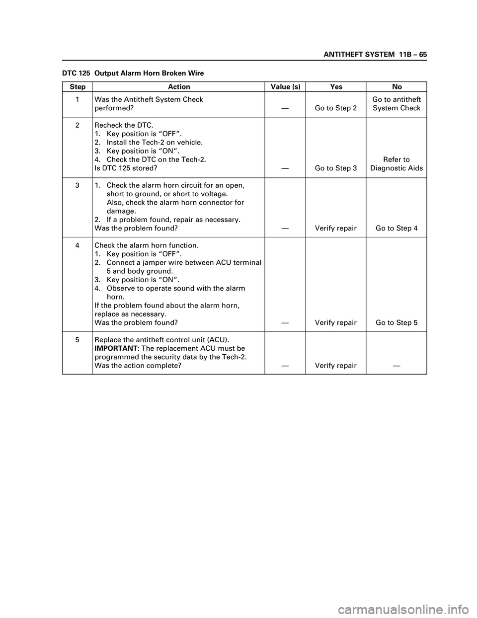
DTC 125 Output Alarm Horn Broken Wire
Step Action Value (s) Yes No
1
2
3
4
5Was the Antitheft System Check
performed?
Recheck the DTC.
1. Key position is “OFF”.
2. Install the Tech-2 on vehicle.
3. Key position is “ON”.
4. Check the DTC on the Tech-2.
Is DTC 125 stored?
1. Check the alarm horn circuit for an open,
short to ground, or short to voltage.
Also, check the alarm horn connector for
damage.
2. If a problem found, repair as necessary.
Was the problem found?
Check the alarm horn function.
1. Key position is “OFF”.
2. Connect a jamper wire between ACU terminal
5 and body ground.
3. Key position is “ON”.
4. Observe to operate sound with the alarm
horn.
If the problem found about the alarm horn,
replace as necessary.
Was the problem found?
Replace the antitheft control unit (ACU).
IMPORTANT:The replacement ACU must be
programmed the security data by the Tech-2.
Was the action complete?—
—
—
—
—Go to Step 2
Go to Step 3
Verify repair
Verify repair
Verify repairGo to antitheft
System Check
Refer to
Diagnostic Aids
Go to Step 4
Go to Step 5
—