ISUZU TF SERIES 2004 Workshop Manual
TF SERIES 2004
ISUZU
ISUZU
https://www.carmanualsonline.info/img/61/57180/w960_57180-0.png
ISUZU TF SERIES 2004 Workshop Manual
Trending: Combination wiring, air suspension, clock, fuse diagram, fuel consumption, engine remove, high beam
Page 3901 of 4264
UNIT REPAIR (AW30–40LE) 7A4–93
Disassembly
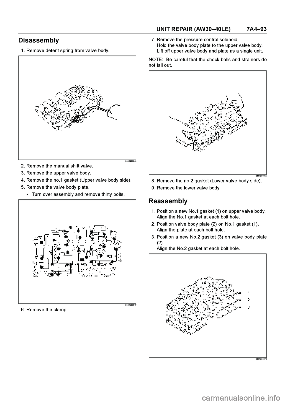
1. Remove detent spring from valve body.
2 40R20 004 0
2. Remove the manual shift valve.
3. Remove the upper valve body.
4. Remove the no.1 gasket (Upper valve body side).
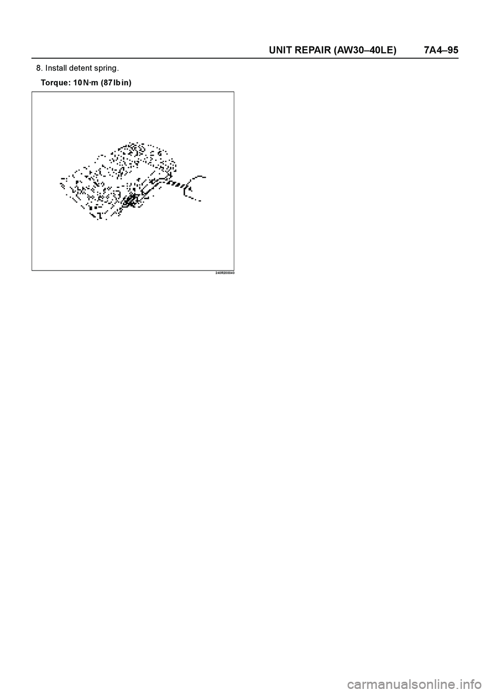
5. Remove the valve body plate.
Turn over assembly and remove thirty bolts.
2 44R20 004 9
6. Remove the clamp.7. Remove the pressure control solenoid.
Hold the valve body plate to the upper valve body.
Lift off upper valve body and plate as a single unit.
NOTE: Be careful that the check balls and strainers do
not fall out.
2 44R20 0061
8. Remove the no.2 gasket (Lower valve body side).
9. Remove the lower valve body.
Reassembly
1. Position a new No.1 gasket (1) on upper valve body.
Align the No.1 gasket at each bolt hole.
2. Position valve body plate (2) on No.1 gasket (1).
Align the plate at each bolt hole.
3. Position a new No.2 gasket (3) on valve body plate
(2).
Align the No.2 gasket at each bolt hole.
2 44R20 0073
Page 3902 of 4264
7A4–94 UNIT REPAIR (AW30–40LE)
4. Place upper valve body with plate and gaskets on
top of lower valve body.
Align each bolt hole and gasket in the valve body.
2 44R20 007 4
5. Install the pressure control solenoid and clamp.
6. Install thirty bolts to upper valve body.
Each bolt is indicated in the figure.
Torque: 6.4 N·m (57Ibin)
2 44R20 0050
7. Install manual shift valve.
Length (mm) Quantity
A207
B2812
C4011
Page 3903 of 4264
UNIT REPAIR (AW30–40LE) 7A4–95
8. Install detent spring.
Torque: 10 N·m (87Ibin)
2 40R20 004 0
Page 3904 of 4264
7A4–96 UNIT REPAIR (AW30–40LE)
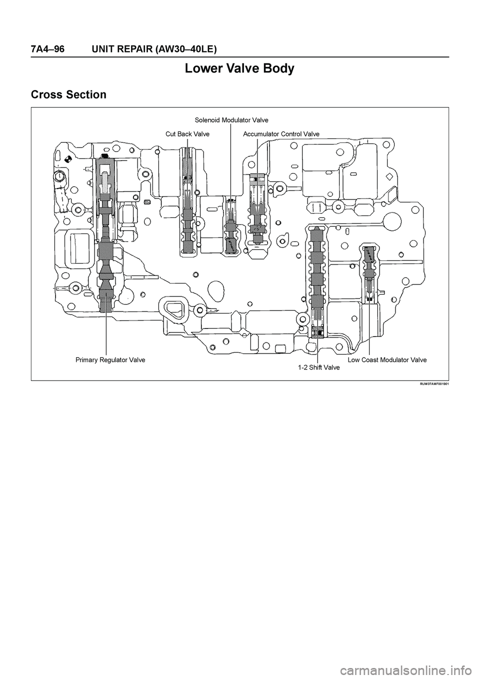
Lower Valve Body
Cross Section
RUW 37A M F00 1901
Page 3905 of 4264
UNIT REPAIR (AW30–40LE) 7A4–97
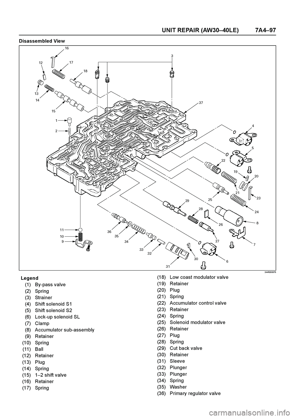
Disassembled View
2 44R20 0075
Legend
(1) By-pass valve
(2) Spring
(3) Strainer
(4) Shift solenoid S1
(5) Shift solenoid S2
(6) Lock-up solenoid SL
(7) Clamp
(8) Accumulator sub-assembly
(9) Retainer
(10) Spring
(11) Ball
(12) Retainer
(13) Plug
(14) Spring
(15) 1–2 shift valve
(16) Retainer
(17) Spring(18) Low coast modulator valve
(19) Retainer
(20) Plug
(21) Spring
(22) Accumulator control valve
(23) Retainer
(24) Spring
(25) Solenoid modulator valve
(26) Retainer
(27) Plug
(28) Spring
(29) Cut back valve
(30) Retainer
(31) Sleeve
(32) Plunger
(33) Plunger
(34) Spring
(35) Washer
(36) Primary regulator valve
Page 3906 of 4264
7A4–98 UNIT REPAIR (AW30–40LE)
E nd O FCallo ut
Disassembly
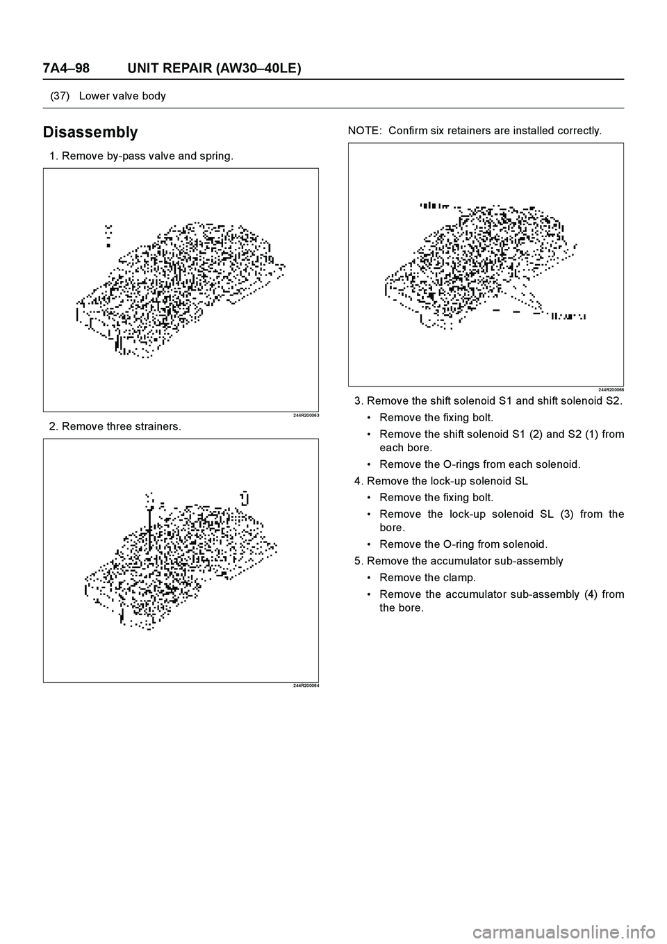
1. Remove by-pass valve and spring.
2 44R20 006 3
2. Remove three strainers.
2 44R20 006 4
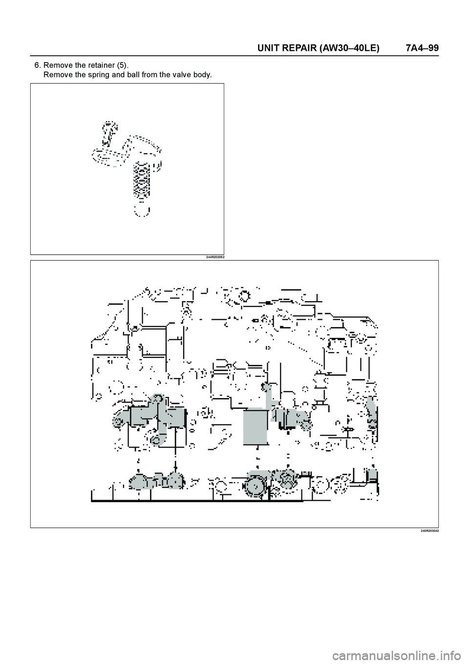
NOTE: Confirm six retainers are installed correctly.
2 44R20 0066
3. Remove the shift solenoid S1 and shift solenoid S2.
Remove the fix ing bolt.
Remove the shift solenoid S1 (2) and S2 (1) from
each bore.
Remove the O-rings from each solenoid.
4. Remove the lock-up solenoid SL
Remove the fix ing bolt.
Remove the lock-up solenoid SL (3) from the
bore.
Remove the O-ring from solenoid.
5. Remove the accumulator sub-assembly
Remove the clamp.
Remove the accumulator sub-assembly (4) from
the bore. (37) Lower valve body
Page 3907 of 4264
UNIT REPAIR (AW30–40LE) 7A4–99
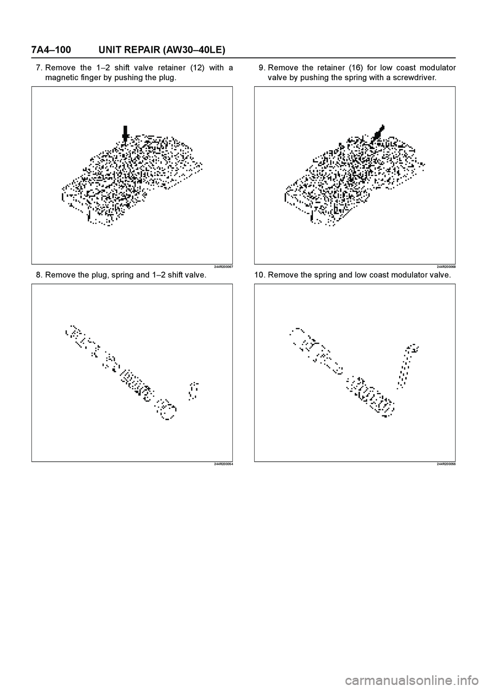
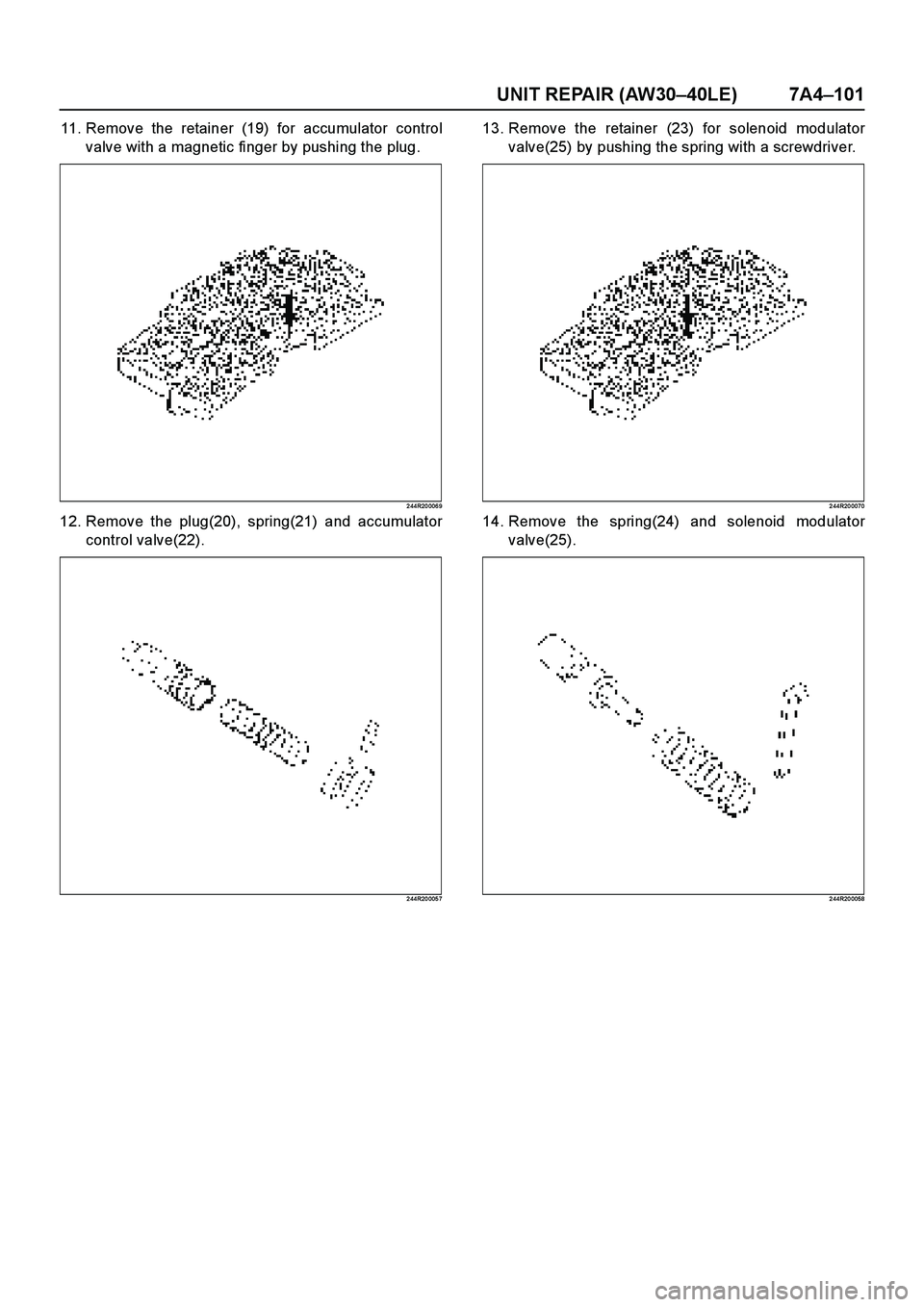
6. Remove the retainer (5).
Remove the spring and ball from the valve body.
2 44R20 005 2
2 40R20 0042
Page 3908 of 4264
7A4–100 UNIT REPAIR (AW30–40LE)
7. Remove the 1–2 shift valve retainer (12) with a
magnetic finger by pushing the plug.
2 44R20 006 7
8. Remove the plug, spring and 1–2 shift valve.
2 44R20 005 4
9. Remove the retainer (16) for low coast modulator
valve by pushing the spring with a screwdriver.
2 44R20 0068
10. Remove the spring and low coast modulator valve.
2 44R20 0056
Page 3909 of 4264
UNIT REPAIR (AW30–40LE) 7A4–101
11. Remove the retainer (19) for accumulator control
valve with a magnetic finger by pushing the plug.
2 44R20 006 9
12. Remove the plug(20), spring(21) and accumulator
control valve(22).
2 44R20 005 7
13. Remove the retainer (23) for solenoid modulator
valve(25) by pushing the spring with a screwdriver.
2 44R20 0070
14. Remove the spring(24) and solenoid modulator
valve(25).
2 44R20 0058
Page 3910 of 4264
7A4–102 UNIT REPAIR (AW30–40LE)
15. Remove the retainer(26) for cut back valve(29) with
a magnetic finger by pushing the plug.
2 44R20 007 1
16. Remove the plug(27), spring(28) and cut back
valve(29).
2 44R20 006 5
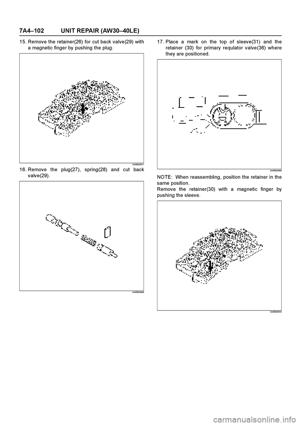
17. Place a mark on the top of sleeve(31) and the
retainer (30) for primary requlator valve(36) where
they are positioned.
2 44R20 0059
NOTE: When reassembling, position the retainer in the
same position.
Remove the retainer(30) with a magnetic finger by
pushing the sleeve.
2 44R20 0072
Trending: Combination wiring, Hard start, oil filter, spark plugs replace, 6A 75, coolant reservoir, manual radio set
