ISUZU TF SERIES 2004 Workshop Manual
TF SERIES 2004
ISUZU
ISUZU
https://www.carmanualsonline.info/img/61/57180/w960_57180-0.png
ISUZU TF SERIES 2004 Workshop Manual
Trending: Combination wiring, door lock, hood open, ecm circuit diagram 6ve1, service, airbag off, 4WD
Page 3921 of 4264
UNIT REPAIR (AW30–40LE) 7A4–11 3
8. Remove the retainer (14) for 2–3 shift valve with a
magnetic finger by pushing the plug.
2 43R20 006 9
9. Remove the plug(15), spring(16) and 2–3 shift
valve(17).
2 43R20 005 8
10. Remove the retainer (18) for reverse control valve
with a magnetic finger by pushing in the plug.
2 43R20 0068
11. Remove the plug(19), spring(20) and reverse
control valve(21).
2 43R20 0060
Page 3922 of 4264
7A4–114 UNIT REPAIR (AW30–40LE)
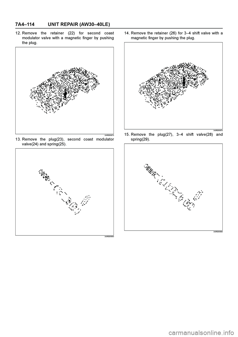
12. Remove the retainer (22) for second coast
modulator valve with a magnetic finger by pushing
the plug.
2 43R20 007 3
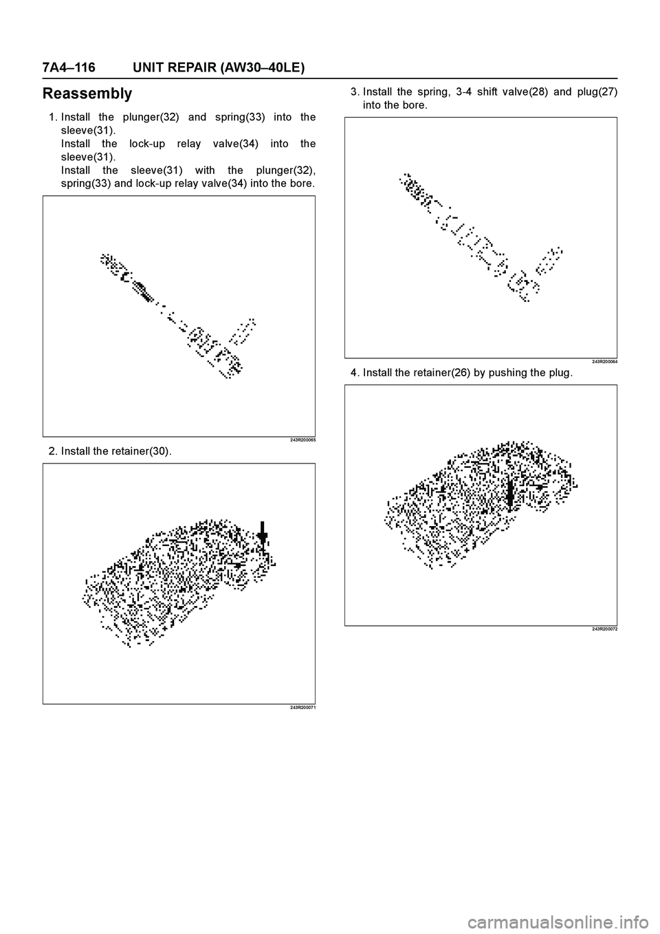
13. Remove the plug(23), second coast modulator
valve(24) and spring(25).
2 43R20 006 3
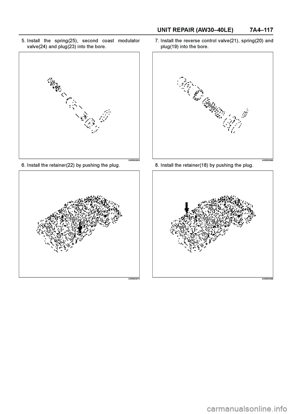
14. Remove the retainer (26) for 3–4 shift valve with a
magnetic finger by pushing the plug.
2 43R20 0072
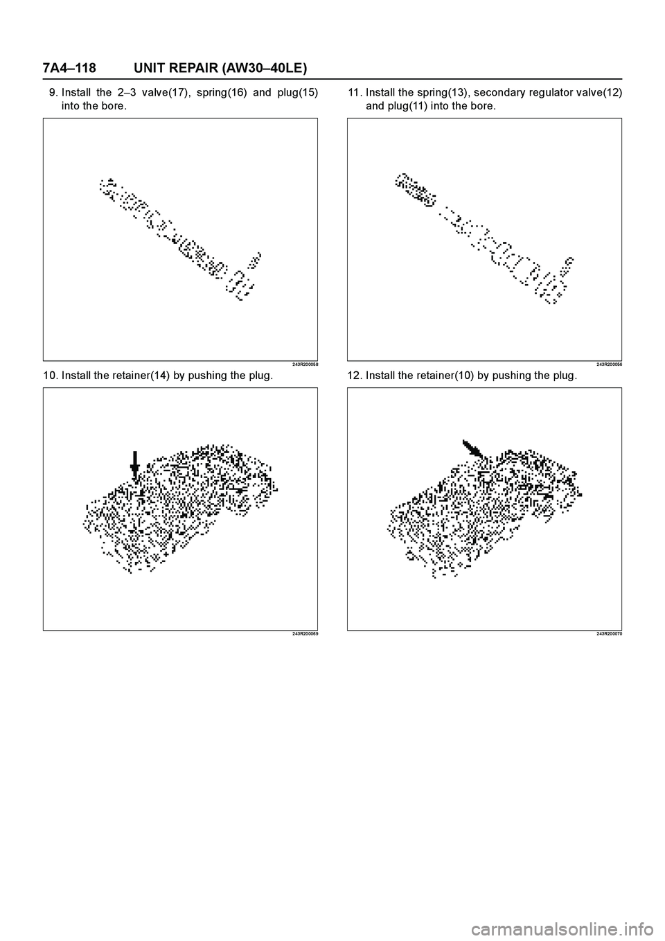
15. Remove the plug(27), 3–4 shift valve(28) and
spring(29).
2 43R20 0064
Page 3923 of 4264
UNIT REPAIR (AW30–40LE) 7A4–11 5
16. Remove the retainer (30) for lock-up relay valve with
a magnetic finger by pushing in the sleeve.
2 43R20 007 1
17. Remove the sleeve(31) with the plunger(32),
spring(33) and lock-up relay valve(34).
Remove the lock-up relay valve(34), spring(33) and
plunger(32) from the sleeve(31).
2 43R20 006 5
Inspection and Repair
1. Inspect valve springs
Check for damage, squareness, rust and distorted
coils.
Measure the spring free length and replace if less
than below.
mm (in)
2 43R20 0076
SpringFree
lengthColor
(1) Secondary regulator valve32.9
(1.295)PURPLE
(2) 2–3 shift valve30.8
(1.213)PURPLE
(3) Reverse control valve25.6
(1.008)—
(4) Second coast modulator
valve25.3
(0.996)ORANGE
(5) 3–4 shift valve30.8
(1.213)PURPLE
(6) Lock-up relay valve 23.4
(0.912)RED
Page 3924 of 4264
7A4–116 UNIT REPAIR (AW30–40LE)
Reassembly
1. Install the plunger(32) and spring(33) into the
sleeve(31).
Install the lock-up relay valve(34) into the
sleeve(31).
Install the sleeve(31) with the plunger(32),
spring(33) and lock-up relay valve(34) into the bore.
2 43R20 006 5
2. Install the retainer(30).
2 43R20 007 1
3. Install the spring, 3-4 shift valve(28) and plug(27)
into the bore.
2 43R20 0064
4. Install the retainer(26) by pushing the plug.
2 43R20 0072
Page 3925 of 4264
UNIT REPAIR (AW30–40LE) 7A4–11 7
5. Install the spring(25), second coast modulator
valve(24) and plug(23) into the bore.
2 43R20 006 3
6. Install the retainer(22) by pushing the plug.
2 43R20 007 3
7. Install the reverse control valve(21), spring(20) and
plug(19) into the bore.
2 43R20 0060
8. Install the retainer(18) by pushing the plug.
2 43R20 0068
Page 3926 of 4264
7A4–118 UNIT REPAIR (AW30–40LE)
9. Install the 2–3 valve(17), spring(16) and plug(15)
into the bore.
2 43R20 005 8
10. Install the retainer(14) by pushing the plug.
2 43R20 006 9
11. Install the spring(13), secondary regulator valve(12)
and plug(11) into the bore.
2 43R20 0056
12. Install the retainer(10) by pushing the plug.
2 43R20 0070
Page 3927 of 4264
UNIT REPAIR (AW30–40LE) 7A4–11 9
13. Install the check valve NO.1(9), ball(8) and check
valve NO.2(7) to valve body.
2 43R20 006 2
14. Install the retainer(6).
2 43R20 006 7
15. Install the check valve NO.1(5), ball(4) and check
valve NO.2(3) to the valve body.
2 43R20 0062
16. Install the retainer(2).
2 43R20 0066
Page 3928 of 4264
7A4–120 UNIT REPAIR (AW30–40LE)
NOTE: Make sure eight retainers are installed correctly
2 43R20 005 4
17. Install the two types of check balls(1) to the valve
body.
Number of check ball : 11
RUW 37A SH00 480 1
Check ball Diameter
(A) Rubber ball 5.535 mm (0.2179 in
(B) Rubber ball 6.35 mm (0.2500 in
Page 3929 of 4264
UNIT REPAIR (AW30–40LE) 7A4–121
Transmission Case
Disassembled View
24 9RY 0 0001
E nd O FCallo ut
Disassembly
1. Using a chisel, cut off the spacer and remove it from
the shaft.
24 9RY 0 0002
Legend
(1) Spacer
(2) Pin
(3) Manual valve lever shaft(4) Manual valve lever
(5) Oil seal
(6) Oil seal
Page 3930 of 4264
7A4–122 UNIT REPAIR (AW30–40LE)
2. Using a punch, drive out the pin.
24 9RY 0 000 3
3. Pull the manual valve lever shaft out through the
case by the threads.
4. Take out the manual valve lever.
5. Using a screwdriver, remove the oil seals.
24 9RY 0 000 4
Reassembly
1. Coat a new oil seal lip with multi purpose grease.
Using special tool, drive in the oil seal.
Oil seal installer : J–37232–2
RTW3 7A SH00 0701
2. Assemble a new spacer to the manual valve lever.
3. Install the manual valve lever shaft to the
transmission case through the manual valve lever
by the threads.
24 9RY 0 0005
Trending: change key battery, ECU, fuel tank capacity, spark plugs replace, catalytic converter, reverse switch, gas type

