ISUZU TF SERIES 2004 Workshop Manual
TF SERIES 2004
ISUZU
ISUZU
https://www.carmanualsonline.info/img/61/57180/w960_57180-0.png
ISUZU TF SERIES 2004 Workshop Manual
Trending: spare wheel, AUX, maintenance reset, fuse, tow, suspension, fuel
Page 3891 of 4264
UNIT REPAIR (AW30–40LE) 7A4–83
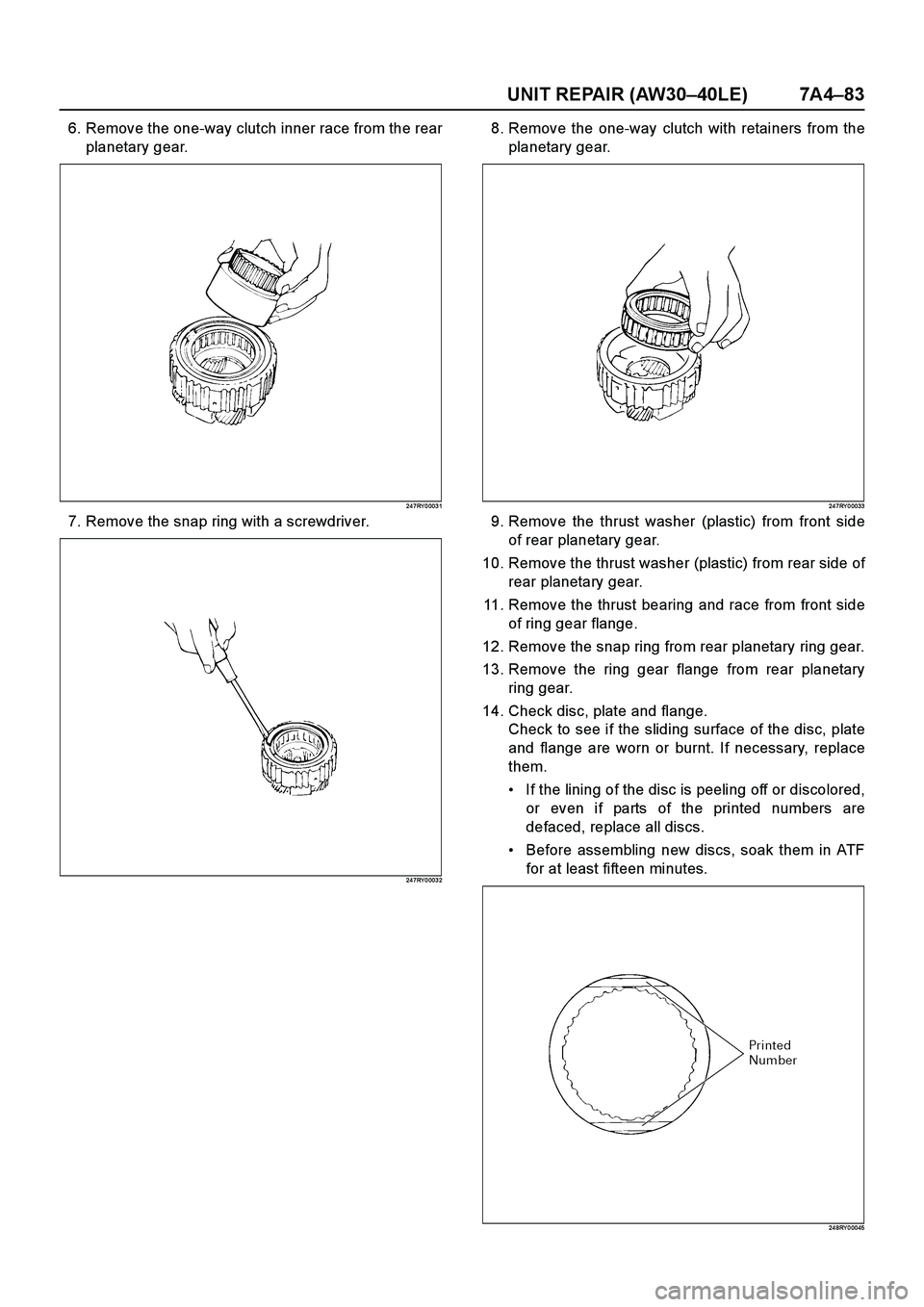
6. Remove the one-way clutch inner race from the rear
planetary gear.
24 7RY 0 003 1
7. Remove the snap ring with a screwdriver.
24 7RY 0 003 2
8. Remove the one-way clutch with retainers from the
planetary gear.
24 7RY 0 0033
9. Remove the thrust washer (plastic) from front side
of rear planetary gear.
10. Remove the thrust washer (plastic) from rear side of
rear planetary gear.
11. Remove the thrust bearing and race from front side
of ring gear flange.
12. Remove the snap ring from rear planetary ring gear.
13. Remove the ring gear flange from rear planetary
ring gear.
14. Check disc, plate and flange.
Check to see if the sliding surface of the disc, plate
and flange are worn or burnt. If necessary, replace
them.
If the lining of the disc is peeling off or discolored,
or even if parts of the printed numbers are
defaced, replace all discs.
Before assembling new discs, soak them in ATF
for at least fifteen minutes.
24 8RY 0 0045
Page 3892 of 4264
7A4–84 UNIT REPAIR (AW30–40LE)
Reassembly
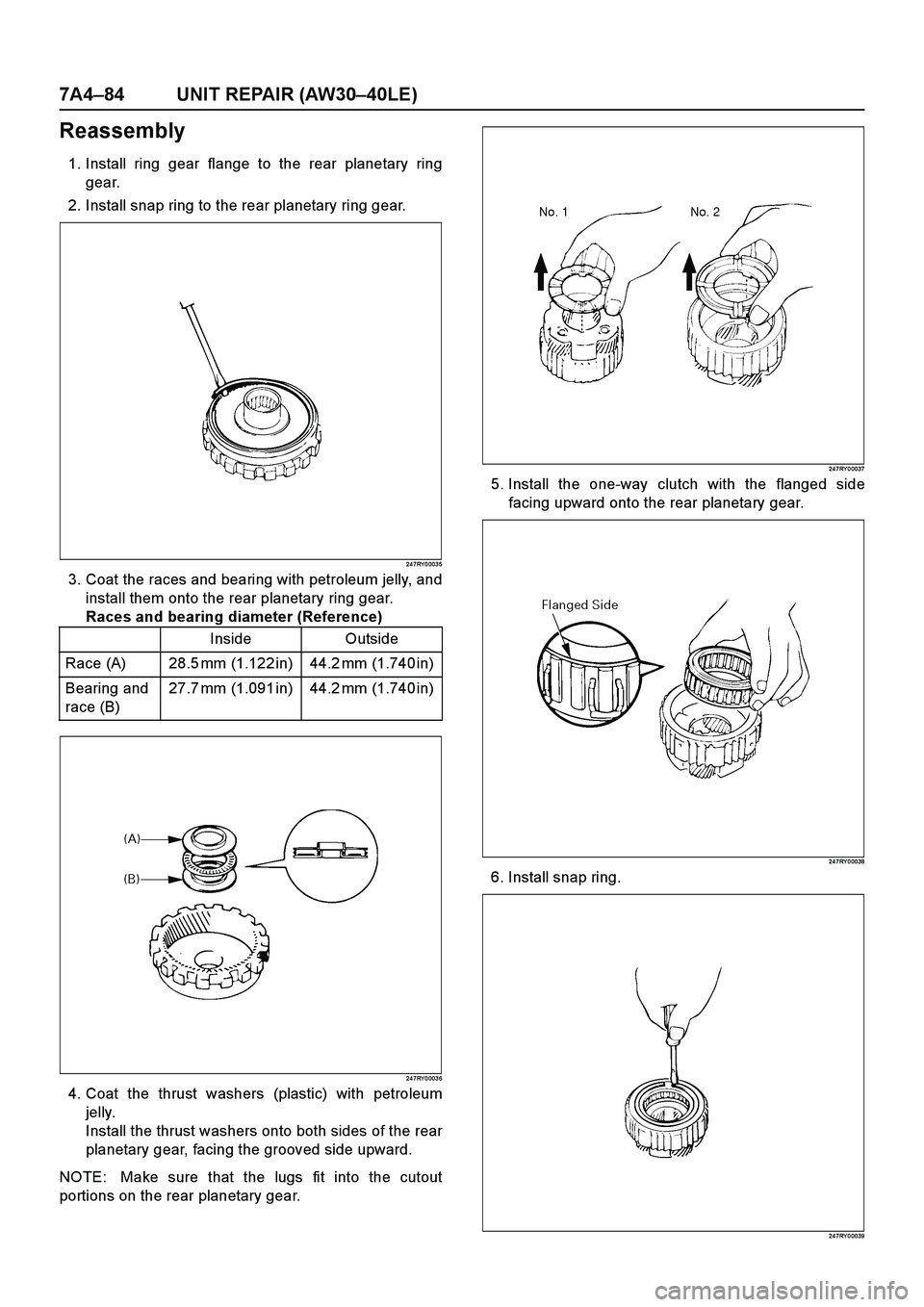
1. Install ring gear flange to the rear planetary ring
gear.
2. Install snap ring to the rear planetary ring gear.
24 7RY 0 003 5
3. Coat the races and bearing with petroleum jelly, and
install them onto the rear planetary ring gear.
Races and bearing diameter (Reference)
24 7RY 0 003 6
4. Coat the thrust washers (plastic) with petroleum
jelly.
Install the thrust washers onto both sides of the rear
planetary gear, facing the grooved side upward.
NOTE: Make sure that the lugs fit into the cutout
portions on the rear planetary gear.
24 7RY 0 0037
5. Install the one-way clutch with the flanged side
facing upward onto the rear planetary gear.
24 7RY 0 0038
6. Install snap ring.
24 7RY 0 0039
Inside Outside
Race (A) 28.5 mm (1.122 in) 44.2 mm (1.740 in)
Bearing and
race (B)27.7 mm (1.091 in) 44.2 mm (1.740 in)
Page 3893 of 4264
UNIT REPAIR (AW30–40LE) 7A4–85
7. While turning counterclockwise, install one-way
clutch inner race to rear planetary gear.
24 7RY 0 004 0
8. Check operation of one-way clutch.
Hold the planetary gear and turn the one-way clutch
inner race.
The one-way clutch inner race should turn freely
counterclockwise and should lock clockwise.
RUW 37A SH00 470 1
E nd OFCa llou t
9. Install rear planetary gear onto rear planetary ring
gear.
24 7RY 0 0029
10. Install the disc, plate and flange (B–3).
Install a brake flange onto the rear planetary gear
assembly.
Install a clutch disc onto the rear planetary gear
assembly.
NOTE: The claw interval of the plate should be as
shown in the figure when viewing the clutch plate from
the arrow direction.
24 6RY 0 0013
Legend
(1) Lock
(2) Free
Page 3894 of 4264
7A4–86 UNIT REPAIR (AW30–40LE)
Install six clutch discs and six brake plates
alternately, starting with clutch disc, onto the rear
planetary gear assembly.
24 7RY 0 004 7
11. Coat the oil seal ring with ATF and install it to the
output shaft.
NOTE: Do not spread the ring ends too much.
24 7RY 0 002 8
12. Install output shaft into rear planetary gear
assembly.
24 7RY 0 0042
13. Install second brake assembly to output shaft.
24 6RY 0 0014
Page 3895 of 4264
UNIT REPAIR (AW30–40LE) 7A4–87
First and Reverse Brake (B–3)
Disassembled View
24 6RY 0 0024
E nd O FCallo ut
Legend
(1) Thrust bearing and race
(2) Snap ring
(3) Piston return spring
(4) First and reverse brake piston No.2(5) O-ring
(6) Reaction sleeve
(7) O-ring
(8) First and reverse brake piston No.1
(9) O-ring
Page 3896 of 4264
7A4–88 UNIT REPAIR (AW30–40LE)
Disassembly
1. Remove assembled thrust bearing and race from
transmission case.
24 7RY 0 004 3
2. Check first and reverse brake piston movement.
Make sure that first and reverse brake piston moves
smoothly when applying and releasing the
compressed air into the transmission case.
24 6RY 0 001 6
3. Set special tool on the spring retainer, and
compress the return spring.
Spring compressor: J–25048
Remove the snap ring with snap ring pliers.
24 7RY 0 0002
4. Remove the piston return spring.
5. Remove the first and reverse brake piston No.2.
Holding the first and reverse brake piston No.2 by
hand, apply compressed air to the transmission
case to remove the first and reverse brake piston
No.2.
Remove the first and reverse brake piston No.2.
If the piston does not pop out with compressed air,
lift the piston out with needle-nose pliers.
24 6RY 0 0016
Page 3897 of 4264

UNIT REPAIR (AW30–40LE) 7A4–89
6. Remove the O-ring from first and reverse brake
piston No.2.
7. Remove the reaction sleeve.
Insert special tool behind the reaction sleeve and
gradually lift it out of the transmission case.
Reaction sleeve puller: J–37236
RUW 37A SH00 330 1
8. Remove the O-ring from reaction sleeve.
9. Remove the first and reverse brake piston No.1.
Insert special tool behind the first and reverse brake
piston No.1 and gradually lift it out of the
transmission case.
Piston puller: J–37237
RUW 37A SH00 340 1
10. Remove the O-rings from first and reverse brake
pistion No.1.
Reassembly
1. Coat three new O-rings with ATF.
Install the two O-rings on the No.1 piston.
2. Install the O-ring on the reaction sleeve.
3. Install the first and reverse brake piston No.1 to the
reaction sleeve.
24 6RY 0 0018
4. Coat a new O-ring with ATF and install it on the first
and reverse brake piston No.2.
5. Install the first and reverse brake piston No.1 with
reaction sleeve onto the first and reverse brake
piston No.2.
24 6RY 0 0019
Page 3898 of 4264
7A4–90 UNIT REPAIR (AW30–40LE)
6. Align the teeth of the first and reverse brake piston
No.2 into the proper grooves.
Being careful not to damage the O-rings, press in
the first and reverse brake piston No.2 with No.1
into the transmission case.
24 6RY 0 002 0
7. Place piston return spring onto first and reverse
brake piston No.2.
24 6RY 0 002 1
8. Set special tool as shown, and compress the return
spring with special tool.
Spring compressor: J–25048
Install the snap ring with snap ring pliers.
Be sure the end gap of the snap ring is not aligned
with the spring retainer claw.
24 7RY 0 0002
9. Check first and reverse brake piston movement.
Make sure the first and reverse brake piston moves
smoothly when applying and releasing the
compressed air into the transmission case.
24 6RY 0 0022
Page 3899 of 4264
UNIT REPAIR (AW30–40LE) 7A4–91
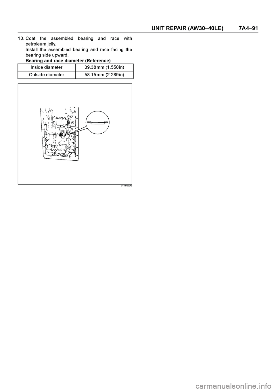
10. Coat the assembled bearing and race with
petroleum jelly.
Install the assembled bearing and race facing the
bearing side upward.
Bearing and race diameter (Reference)
24 7RY 0 004 3
Inside diameter 39.38 mm (1.550 in)
Outside diameter 58.15 mm (2.289 in)
Page 3900 of 4264
7A4–92 UNIT REPAIR (AW30–40LE)
Transmission Valve Body assembly
Disassembled View
2 40R20 0039
E nd O FCallo ut
Legend
(1) Detent spring
(2) Manual shift valve
(3) Upper valve body
(4) No.1 gasket (Upper valve body side)(5) Valve body plate
(6) Clamp
(7) Pressure control solenoid
(8) No.2 gasket (Lower valve body side)
(9) Lower valve body
Trending: brake light, circuit diagram, air condition, mass air flow, lock, sections table, reverse


