brake ISUZU TF SERIES 2004 Owner's Guide
[x] Cancel search | Manufacturer: ISUZU, Model Year: 2004, Model line: TF SERIES, Model: ISUZU TF SERIES 2004Pages: 4264, PDF Size: 72.63 MB
Page 320 of 4264

5A-4 BRAKE CONTROL SYSTEM
DTC C0277 (Flash Code 77) Power Supply Low Input .................................................... 5A-84
DTC C0278 (Flash Code 78) Power Supply High Input ................................................... 5A-84
DTC C0282 (Flash Code 82) 4 Wheel Drive State Input Signal Failure .......................... 5A-86
DTC C0285 (Flash Code 85) Assembly Error (G-sensor) ................................................ 5A-88
Special Tools ...................................................................................................................... 5A-90
Service Precaution
WARNING: THIS VEHICLE HAS A SUPPLEMENTAL
RESTRAINT SYSTEM (SRS). REFER TO THE SRS
COMPONENT AND WIRING LOCATION VIEW IN
ORDER TO DETERMINE WHETHER YOU ARE
PERFORMING SERVICE ON OR NEAR THE SRS
COMPONENTS OR THE SRS WIRING. WHEN YOU
ARE PERFORMING SERVICE ON OR NEAR THE
SRS COMPONENTS OR THE SRS WIRING, REFER
TO THE SRS SERVICE INFORMATION. FAILURE TO
FOLLOW WARNINGS COULD RESULT IN
POSSIBLE AIR BAG DEPLOYMENT, PERSONAL
INJURY, OR OTHERWISE UNNEEDED SRS SYSTEM
REPAIRS.
CAUTION: Always use the correct fastener in the
proper location. When you replace a fastener, use
ONLY the exact part number for that application.
ISUZU will call out those fasteners that require a
replacement after removal. ISUZU will also call out
the fasteners that require thread lockers or thread
sealant. UNLESS OTHERWISE SPECIFIED, do not
use supplemental coatings (Paints, greases, or
other corrosion inhibitors) on threaded fasteners or
fastener joint interfaces. Generally, such coatings
adversely affect the fastener torque and the joint
clamping force, and may damage the fastener.
When you install fasteners, use the correct
tightening sequence and specifications. Following
these instructions can help you avoid damage to
parts and systems.
Page 321 of 4264

BRAKE CONTROL SYSTEM 5A-5
General Description
EHCU has controlled ABS (Anti-lock Brake System)
and EBD (Electronic Brake-force Distribution System).
ABS works on all four wheels. EBD system works on
rear 2 wheels. A combination of wheel speed sensor
and Electronic Hydraulic Control Unit (EHCU) can
determine when a wheel is about to stop turning and
adjust brake pressure to maintain best braking. This system helps the driver maintain greater control of
the vehicle under heavy braking conditions.
Note: The Electronic Hydraulic Control Unit (EHCU)
comprises the Hydraulic Unit (H/U) and Control Unit.
This illustration is based on RHD model
C05L300010
Legend
(1) Electronic (6) Front Left Wheel Speed Sensor
(2) Hydraulic (7) Rear Right Wheel Speed Sensor
(3) Hydraulic Unit (H/U) (8) Rear Left Wheel Speed Sensor
(4) Control Unit (9) G-sensor (4WD only)
(5) Front Right Wheel Speed Sensor (10) 2-4WD Control Unit (4WD only)
Page 322 of 4264

5A-6 BRAKE CONTROL SYSTEM
EHCU, Brake Pipe Diagram
This illustration is based on RHD model
C05L300011
Legend
(1) Front Right Brake Port (out)
(4) Front Brake Port (in)
(2) Front Left Brake Port (out)
(5) Rear Brake Port (in)
(3) Rear Brake Port (out)
Page 323 of 4264

BRAKE CONTROL SYSTEM 5A-7
Hydraulic Unit (H/U)
C05L300004
Legend
(1) Brake Pedal (5) Dump Valve
(2) Master Cylinder
(6) Buffer Chamber
(3) Motor and Pump (7)Brake
(4) Isolation Valve
Page 324 of 4264

5A-8 BRAKE CONTROL SYSTEM
Normal Braking
During normal (non anti-lock) braking, the solenoid
valve has current flow. The dump valve is closed and
the isolation valve is opened due to spring force.
Brake fluid travels through the center of the isolation
valve (normally open) around the dump valve (normally
closed) then to the brake pistons.
C05L300012
Page 325 of 4264

BRAKE CONTROL SYSTEM 5A-9
Pressure Isolation (Pressure Maintain)
The electronic-hydraulic control unit is activated when
the brakes are applied.
If the information from the wheel speed sensors
indicates excessive wheel deceleration (imminent
lockup), the first step in the anti-lock sequence is to
isolate the brake pressure being applied by the brake
pedal.
The microprocessor in the Control Unit sends a voltage
to the coil to energize and close the isolation valve.
This prevents any additional fluid pressure applied by
the brake pedal from reaching the wheel. With the
isolation valves closed, unnecessary increase in the
brake pressure is prevented.
C05L300013
Page 326 of 4264

5A-10 BRAKE CONTROL SYSTEM
Pressure Reduction
Once the brake pressure is isolated, it must be reduced
to allow the wheels to unlock. This is accomplished by
dumping a portion of the brake fluid pressure into a
buffer chamber.
The microprocessor activates the normally closed dump
valve to open, allowing fluid from the wheels to be
dumped into the buffer chamber. This is done with very
short activation pulses opening and closing the dump valve passageway. Brake pressure is reduced at the
wheel and allows the wheel to begin rotating again. The
fluid from the brake piston is stored in the buffer
chamber against spring pressure and a portion of this
fluid also primes the pump.
The dump valves are operated independently to control
the deceleration of the wheel.
C05L300014
Page 327 of 4264

BRAKE CONTROL SYSTEM 5A-11
Brake Release
At the end of the anti-lock stop, when the brake pedal is
released, the pump will remain running for a short time
to help drain any fluid from the buffer chamber. As this
fluid returns into the system, the spring forces the piston back to its original position.
The isolation valve opens and fluid may return to the
master cylinder. Conventional braking is then resumed.
C05L300015
Page 328 of 4264

5A-12 BRAKE CONTROL SYSTEM
Circuit Diagram
RTW45AXF000101
Page 329 of 4264

BRAKE CONTROL SYSTEM 5A-13
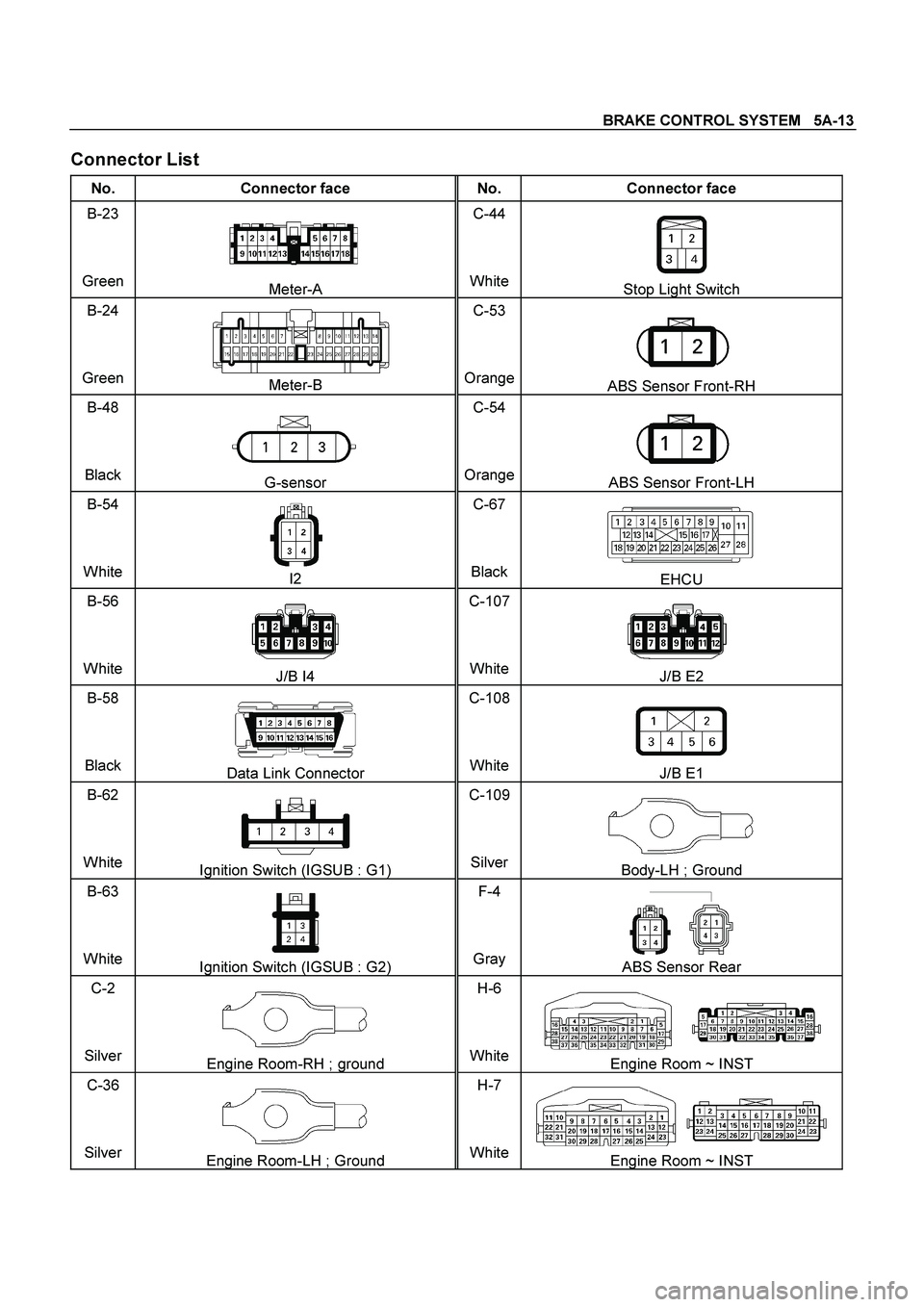
Connector List
No. Connector face No. Connector face
B-23
Green
Meter-A C-44
WhiteStop Light Switch
B-24
Green
Meter-B C-53
OrangeABS Sensor Front-RH
B-48
Black
G-sensor C-54
OrangeABS Sensor Front-LH
B-54
White
I2 C-67
BlackEHCU
B-56
White
J/B I4 C-107
WhiteJ/B E2
B-58
Black
Data Link Connector C-108
WhiteJ/B E1
B-62
White
Ignition Switch (IGSUB : G1) C-109
SilverBody-LH ; Ground
B-63
White
Ignition Switch (IGSUB : G2) F-4
Gray ABS Sensor Rear
C-2
Silver
Engine Room-RH ; ground H-6
WhiteEngine Room ~ INST
C-36
Silver
Engine Room-LH ; Ground H-7
WhiteEngine Room ~ INST