content ISUZU TF SERIES 2004 Repair Manual
[x] Cancel search | Manufacturer: ISUZU, Model Year: 2004, Model line: TF SERIES, Model: ISUZU TF SERIES 2004Pages: 4264, PDF Size: 72.63 MB
Page 2782 of 4264

6E–206 ENGINE DRIVEABILITY AND EMISSIONS
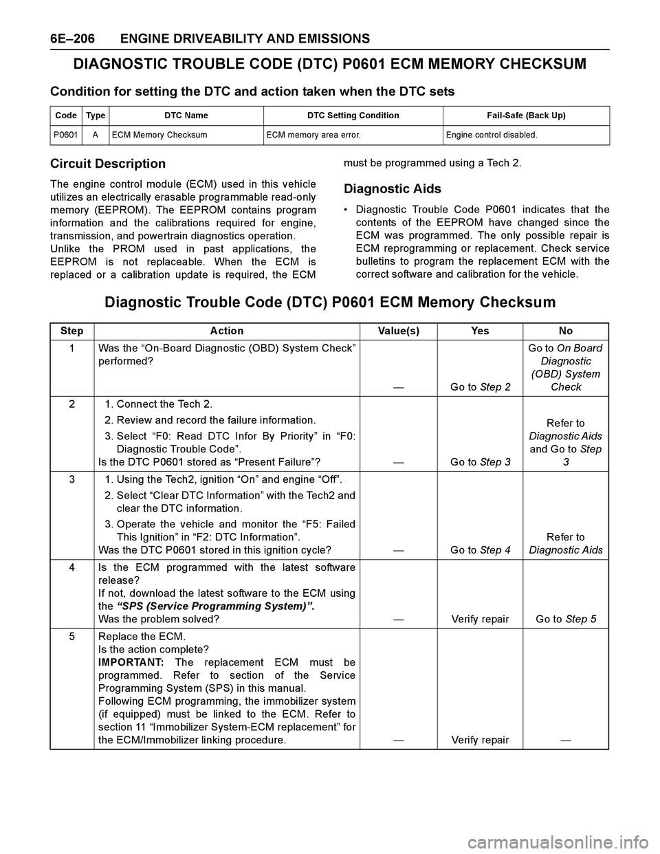
DIAGNOSTIC TROUBLE CODE (DTC) P0601 ECM MEMORY CHECKSUM
Condition for setting the DTC and action taken when the DTC sets
Circuit Description
The engine control module (ECM) used in this vehicle
utilizes an electrically erasable programmable read-only
memory (EEPROM). The EEPROM contains program
information and the calibrations required for engine,
transmission, and powertrain diagnostics operation.
Unlike the PROM used in past applications, the
EEPROM is not replaceable. When the ECM is
replaced or a calibration update is required, the ECMmust be programmed using a Tech 2.Diagnostic Aids
Diagnostic Trouble Code P0601 indicates that the
contents of the EEPROM have changed since the
ECM was programmed. The only possible repair is
ECM reprogramming or replacement. Check service
bulletins to program the replacement ECM with the
correct software and calibration for the vehicle.
Diagnostic Trouble Code (DTC) P0601 ECM Memory Checksum
Code Type DTC Name DTC Setting Condition Fail-Safe (Back Up)
P0601 A ECM Me mo ry Che cksum ECM memo ry are a erro r. Engine co ntrol disabled.
Step A ction Value(s) Yes No
1 Was the “On-Board Diagnostic (OBD) System Check”
performed?
—Go to Step 2Go to On Board
Diagnostic
(OBD) System
Check
2 1. Connect the Tech 2.
2. Review and record the failure information.
3. Select “F0: Read DTC Infor By Priority” in “F0:
Diagnostic Trouble Code”.
Is the DTC P0601 stored as “Present Failure”?—Go to Step 3Refer to
Diagnostic Aids
and Go to Step
3
3 1. Using the Tech2, ignition “On” and engine “Off”.
2. Select “Clear DTC Information” with the Tech2 and
clear the DTC information.
3. Operate the vehicle and monitor the “F5: Failed
This Ignition” in “F2: DTC Information”.
Was the DTC P0601 stored in this ignition cycle?—Go to Step 4Refer to
Diagnostic Aids
4 Is the ECM programmed with the latest software
release?
If not, download the latest software to the ECM using
the “SPS (Service Programming System)”.
Was the problem solved?—Verify repair Go to Step 5
5 Replace the ECM.
Is the action complete?
IMPORTANT: The replacement ECM must be
programmed. Refer to section of the Service
Programming System (SPS) in this manual.
Following ECM programming, the immobilizer system
(if equipped) must be linked to the ECM. Refer to
section 11 “Immobilizer System-ECM replacement” for
the ECM/Immobilizer linking procedure.—Veri fy repai r—
Page 2808 of 4264

6E–232 ENGINE DRIVEABILITY AND EMISSIONS
SYMPTOM DIAGNOSIS
PRELIMINARY CHECKS
Before using this section, perform the “On-Board
Diagnostic (OBD) System Check” and verify all of the
following items:
The engine control module (ECM) and malfunction
indicator lamp (MIL = Check Engine Lamp) are
operating correctly.
There are no Diagnostic Trouble Code(s) stored.
Tech 2 data is within normal operating range. Refer to
Typical Scan Data Values.
Verify the customer complaint and locate the correct
symptom in the table of contents. Perform the
procedure included in the symptom chart.
VISUAL/PHYSICAL CHECK
Several of the symptom procedures call for a careful
visual/physical check. This can lead to correcting a
problem without further checks and can save valuable
time. This check should include the following items:
ECM grounds for cleanliness, tightness and proper
location.
Vacuum hoses for splits, kinks, and proper
connection, shown on the “Emission Control System
Schematics”. Check thoroughly for any type of leak or
restriction.
Air intake ducts for collapsed or damaged areas.
Air leaks at throttle body mounting area, manifold
absolute pressure (MAP) sensor and intake manifold
sealing surfaces.
Ignition wires for cracking, harness, and carbon
tracking.
Wiring for proper connections, pinches and cuts.
INTERMITTENT
Important: An intermittent problem may or may not turn
on the malfunction indicator lamp (MIL) or store a
Diagnostic Trouble Code. Do NOT use the Diagnostic
Trouble Code (DTC) charts for intermittent problems.
The fault must be present to locate the problem.
Most intermittent problems are cased by faulty electrical
connections or wiring. Perform a careful visual/physical
check for the following conditions.
Poor mating of the connector halves or a terminal not
fully seated in the connector (backed out).
Improperly formed or damaged terminal.
All connector terminals in the problem circuit should
be carefully checked for proper contact tension.
Poor terminal-to-wire connection. This requires
removing the terminal form the connector body to
check.
Ignition coils shorted to ground and arcing at ignition
wires or plugs.MIL (Check Engine Lamp) wire to ECM shorted to
ground.
Poor ECM grounds. Refer to the ECM wiring
diagrams.
Road test the vehicle with a Digital Multimeter
connected to a suspected circuit. An abnormal voltage
when the malfunction occurs is a good indication that
there is a fault in the circuit being monitored.
Using Tech 2 to help detect intermittent conditions. The
Tech 2 has several features that can be used to located
an intermittent condition.
An intermittent MIL (Check Engine Lamp) with no stored
Diagnostic Trouble Code may be caused by the
follow ing:
Ignition coil shorted to ground and arcing at ignition
wires or plugs.
MIL (Check Engine Lamp) wire to ECM short to
ground.
Poor ECM grounds. Refer to the ECM wiring
diagrams.
Check for improper installation of electrical options such
as light, cellular phones, etc. Check all wires from ECM
to the ignition control module for poor connections.
Check for an open diode across the A/C compressor
clutch and check for other open diodes (refer to wiring
diagrams in Electrical Diagnosis).
If problem has not been found, refer to ECM connector
symptom tables.
Check the “Broadcast Code” of the ECM, and
compare it with the latest Isuzu service bulletins and/
or Isuzu EEPROM reprogramming equipment to
determine if an update to the ECM’s reprogrammable
memory has been released.
To check the “Broadcast Code”, connect the Tech 2,
then look for “ID info.” then select “Broadcast Code”.
This should display a 4 character code, such as “XBYA”
(ex ample only).
This identifies the contents of the reprogrammable
software and calibration contained in the ECM.
If the “Broadcast Code” is not the most current
available, it is advisable to reprogram the ECM’s
EEPROM memory, which may either help identify a
hard-to find problem or may fix the problem.
The Service Programming System (SPS) will not allow
incorrect software programming or incorrect calibration
changes.
Page 2857 of 4264

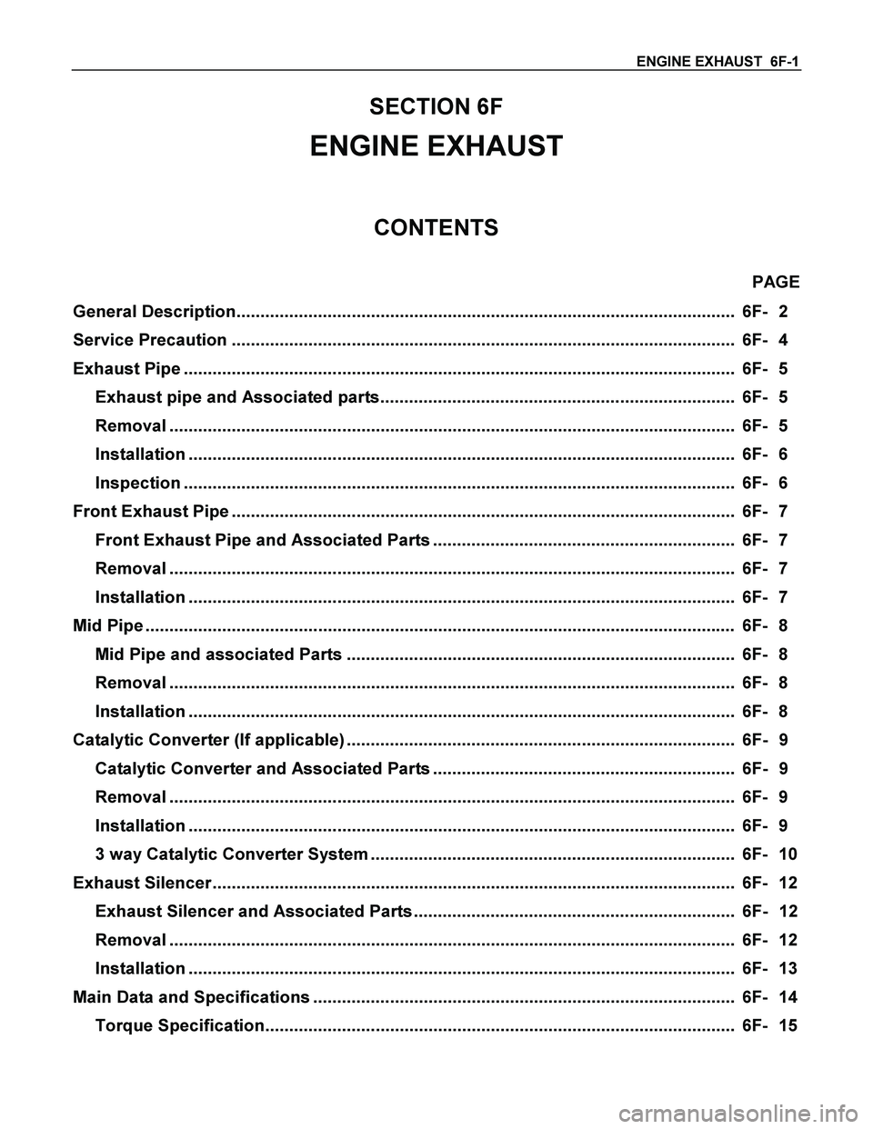
ENGINE EXHAUST 6F-1
SECTION 6F
ENGINE EXHAUST
CONTENTS
PAGE
General Description........................................................................................................ 6F- 2
Service Precaution ......................................................................................................... 6F- 4
Exhaust Pipe ................................................................................................................... 6F- 5
Exhaust pipe and Associated parts.......................................................................... 6F- 5
Removal ...................................................................................................................... 6F- 5
Installation .................................................................................................................. 6F- 6
Inspection ................................................................................................................... 6F- 6
Front Exhaust Pipe ......................................................................................................... 6F- 7
Front Exhaust Pipe and Associated Parts ............................................................... 6F- 7
Removal ...................................................................................................................... 6F- 7
Installation .................................................................................................................. 6F- 7
Mid Pipe ........................................................................................................................... 6F- 8
Mid Pipe and associated Parts ................................................................................. 6F- 8
Removal ...................................................................................................................... 6F- 8
Installation .................................................................................................................. 6F- 8
Catalytic Converter (If applicable) ................................................................................. 6F- 9
Catalytic Converter and Associated Parts ............................................................... 6F- 9
Removal ...................................................................................................................... 6F- 9
Installation .................................................................................................................. 6F- 9
3 way Catalytic Converter System ............................................................................ 6F- 10
Exhaust Silencer ............................................................................................................. 6F- 12
Exhaust Silencer and Associated Parts ................................................................... 6F- 12
Removal ...................................................................................................................... 6F- 12
Installation .................................................................................................................. 6F- 13
Main Data and Specifications ........................................................................................ 6F- 14
Torque Specification.................................................................................................. 6F- 15
Page 2873 of 4264

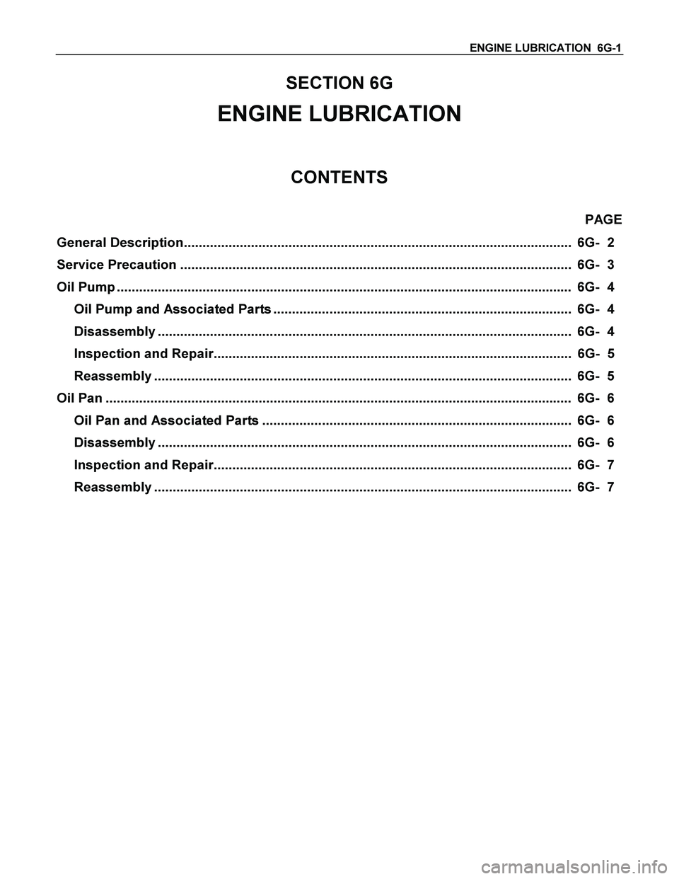
ENGINE LUBRICATION 6G-1
SECTION 6G
ENGINE LUBRICATION
CONTENTS
PAGE
General Description........................................................................................................ 6G- 2
Service Precaution ......................................................................................................... 6G- 3
Oil Pump .......................................................................................................................... 6G- 4
Oil Pump and Associated Parts ................................................................................ 6G- 4
Disassembly ............................................................................................................... 6G- 4
Inspection and Repair................................................................................................ 6G- 5
Reassembly ................................................................................................................ 6G- 5
Oil Pan ............................................................................................................................. 6G- 6
Oil Pan and Associated Parts ................................................................................... 6G- 6
Disassembly ............................................................................................................... 6G- 6
Inspection and Repair................................................................................................ 6G- 7
Reassembly ................................................................................................................ 6G- 7
Page 2881 of 4264

ENGINE SPEED CONTROL SYSTEM (C24SE) 6H-1
ENGINE
ENGINE SPEED CONTROL SYSTEM (C24SE)
CONTENTS
Service Precaution............................................... 6H-1
Accelerator Pedal Control Cable...................... 6H-2
Removal.............................................................. 6H-2
Inspection........................................................... 6H-3
Installation.......................................................... 6H-3
Service Precaution
WARNING: THIS VEHICLE HAS A SUPPLEMENTAL
RESTRAINT SYSTEM (SRS). REFER TO THE SRS
COMPONENT AND WIRING LOCATION VIEW IN
ORDER TO DETERMINE WHETHER YOU ARE
PERFORMING SERVICE ON OR NEAR THE SRS
COMPONENTS OR THE SRS WIRING. WHEN YOU
ARE PERFORMING SERVICE ON OR NEAR THE
SRS COMPONENTS OR THE SRS WIRING, REFE
R
TO THE SRS SERVICE INFORMATION. FAILURE TO
FOLLOW WARNINGS COULD RESULT IN
POSSIBLE AIR BAG DEPLOYMENT, PERSONAL
INJURY, OR OTHERWISE UNNEEDED SRS SYSTEM
REPAIRS.
CAUTION: Always use the correct fastener in the
proper location. When you replace a fastener, use
ONLY the exact part number for that application.
ISUZU will call out those fasteners that require a
replacement after removal. ISUZU will also call out
the fasteners that require thread lockers or thread
sealant. UNLESS OTHERWISE SPECIFIED, do not
use supplemental coatings (Paints, greases, o
r
other corrosion inhibitors) on threaded fasteners o
r
fastener joint interfaces. Generally, such coatings
adversely affect the fastener torque and the joint
clamping force, and may damage the fastener.
When you install fasteners, use the correct
tightening sequence and specifications. Following
these instructions can help you avoid damage to
parts and systems.
Page 2885 of 4264

INDUCTION 6J-1
SECTION 6J
INDUCTION
CONTENTS
PAGE
Service Precaution ......................................................................................................... 6J- 2
Air Cleaner Filter ............................................................................................................. 6J- 2
Removal ...................................................................................................................... 6J- 2
Inspection ................................................................................................................... 6J- 2
Installation .................................................................................................................. 6J- 3
Page 2893 of 4264

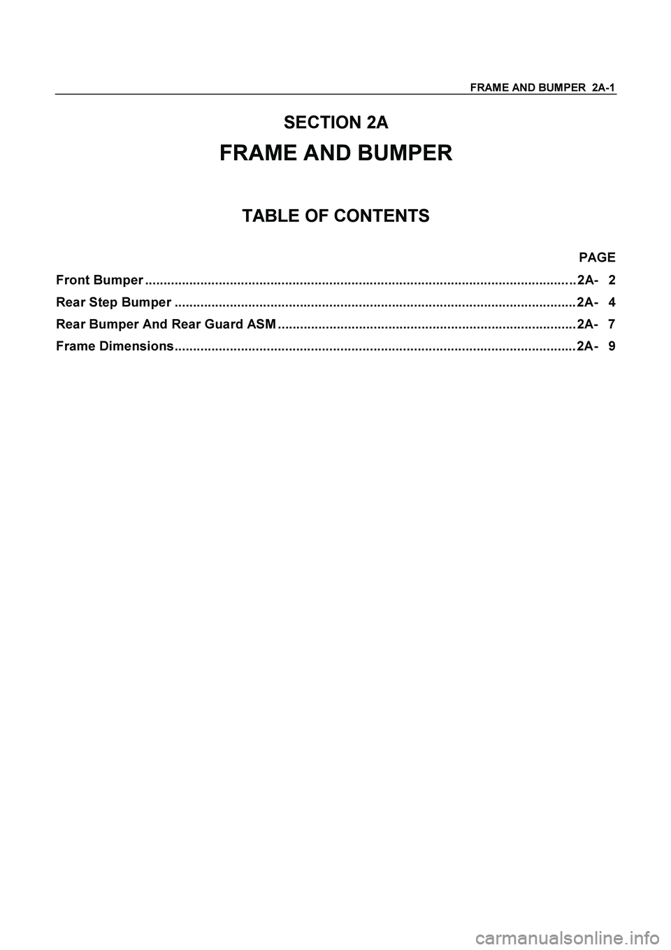
FRAME AND BUMPER 2A-1
SECTION 2A
FRAME AND BUMPER
TABLE OF CONTENTS
PAGE
Front Bumper ..................................................................................................................... 2A- 2
Rear Step Bumper ............................................................................................................. 2A- 4
Rear Bumper And Rear Guard ASM ................................................................................. 2A- 7
Frame Dimensions............................................................................................................. 2A- 9
Page 2933 of 4264

SHEET METAL 2B-1
SECTION 2B
SHEET METAL
This section includes items of front end sheet metal that are attached by bolts, screws or clips and related
accessory components.
Anticorrosion materials have been applied to the interior surfaces of some metal panels to provide rust resistance.
When servicing these panes, areas on which this material has been disturbed, should be properly recoated with
service-type anticorrosion material.
TABLE OF CONTENTS
PAGE
Engine Hood Assembly ..................................................................................................... 2B- 2
Engine Hood Lock ............................................................................................................. 2B- 5
Front Fender Panel ............................................................................................................ 2B- 7
Radiator Grille .................................................................................................................... 2B- 10
Rear Body ........................................................................................................................... 2B- 11
Body Mounting ................................................................................................................... 2B- 13
Body Dimension.................................................................................................................2B- 19
Page 2973 of 4264

GENERAL INFORMATION 0A-1
SECTION 0A
GENERAL INFORMATION
TABLE OF CONTENTS
PAGE
General Repair Instructions ............................................................................................ 0A- 2
Notes on The Format of this Manual .............................................................................. 0A- 3
Identification .................................................................................................................... 0A- 6
Lifting Instructions .......................................................................................................... 0A- 7
Conversion Table............................................................................................................. 0A- 9
Page 2981 of 4264

GENERAL INFORMATION 0A-9
CONVERSION TABLE
TABLE OF CONTENTS
PAGE
Length ............................................................................................................................... 0A- 9
Area ................................................................................................................................... 0A-11
Volume .............................................................................................................................. 0A-11
Mass.................................................................................................................................. 0A-13
Pressure ........................................................................................................................... 0A-14
Torque............................................................................................................................... 0A-15
Temperature ..................................................................................................................... 0A-16
LENGTH
MILLIMETERS TO INCHES
mm in. mm in. mm in. mm in. 1 0.0394 26 1.0236 51 2.0079 76 2.9921 2 0.0787 27 1.0630 52 2.0472 77 3.0315 3 0.1181 28 1.1024 53 2.0866 78 3.0709 4 0.1575 29 1.1417 54 2.1260 79 3.1102 5 0.1969 30 1.1811 55 2.1654 80 3.1496 6 0.2362 31 1.2205 56 2.2047 81 3.1890 7 0.2756 32 1.2598 57 2.2441 82 3.2283 8 0.3150 33 1.2992 58 2.2835 83 3.2677 9 0.3543 34 1.3386 59 2.3228 84 3.307110 0.3937 35 1.3780 60 2.3622 85 3.346511 0.4331 36 1.4173 61 2.4016 86 3.385812 0.4724 37 1.4567 62 2.4409 87 3.425213 0.5118 38 1.4961 63 2.4803 88 3.464614 0.5512 39 1.5354 64 2.5197 89 3.503915 0.5906 40 1.5748 65 2.5591 90 3.543316 0.6299 41 1.6142 66 2.5984 91 3.582717 0.6693 42 1.6535 67 2.6378 92 3.622018 0.7087 43 1.6929 68 2.6772 93 3.661419 0.7480 44 1.7323 69 2.7165 94 3.700820 0.7874 45 1.7717 70 2.7559 95 3.740221 0.8268 46 1.8110 71 2.7953 96 3.779522 0.8661 47 1.8504 72 2.8346 97 3.818923 0.9055 48 1.8898 73 2.8740 98 3.858324 0.9449 49 1.9291 74 2.9134 99 3.897625 0.9843 50 1.9685 75 2.9528 100 3.9370 101 3.9764 111 4.3701 121 4.7638 131 5.1575102 4.0157 112 4.4094 122 4.8031 132 5.1968103 4.0551 113 4.4488 123 4.8425 133 5.2362104 4.0945 114 4.4882 124 4.8819 134 5.2756105 4.1339 115 4.5276 125 4.9213 135 5.3150106 4.1732 116 4.5669 126 4.9606 136 5.3543107 4.2126 117 4.6063 127 5.0000 137 5.3937108 4.2520 118 4.6457 128 5.0394 138 5.4331109 4.2913 119 4.6850 129 5.0787 139 5.4724
INCHES TO MILLIMETERS
in. mm in. mm 1/64 0.3969 33/64 13.0969 1/32 0.7938 17/32 13.4938 3/64 1.1906 35/64 13.89061/16 1.5875 9/16 14.2875 5/64 1.9844 37/64 14.6844 3/32 2.3813 19/32 15.0813 7/64 2.7781 39/64 15.47811/8 3.1750 5/8 15.8750 9/64 3.5719 41/64 16.2719 5/32 3.9688 21/32 16.6688 11/64 4.3656 43/64 17.06563/16 4.7625 11/16 17.4625 13/64 5.1594 45/64 17.8594 7/32 5.5563 23/32 18.2563 15/64 5.9531 47/64 18.65311/4 6.3500 3/4 19.0500 17/64 6.7469 49/64 19.4469 9/32 7.1438 25/32 19.8438 19/64 7.5406 51/64 20.24065/16 7.9375 13/16 20.6375 21/64 8.3344 53/64 21.0344 11/32 8.7313 27/32 21.4313 23/64 9.1281 55/64 21.82813/8 9.5250 7/8 22.2250 25/64 9.9219 57/64 22.6219 13/32 10.3188 29/32 23.0188 27/64 10.7156 59/64 23.41567/16 11.1125 15/16 23.8125 29/64 11.5094 61/64 24.2094 15/32 11.9063 31/32 24.6063 31/64 12.3031 63/64 25.00311/2 12.7000 1 25.4000