section table ISUZU TF SERIES 2004 Repair Manual
[x] Cancel search | Manufacturer: ISUZU, Model Year: 2004, Model line: TF SERIES, Model: ISUZU TF SERIES 2004Pages: 4264, PDF Size: 72.63 MB
Page 2820 of 4264

6E–244 ENGINE DRIVEABILITY AND EMISSIONS
21 Check the ex haust system for a possible restriction:
Damaged or collapsed pipes
Internal muffler failure
Was a problem found?—Verify repair Go to Step 22
22 1. Review all diagnostic procedures within this table.
2. If all procedures have been completed and no
malfunctions have been found, review/inspect the
followi ng:
Visual/physical inspection
Te c h 2 d a t a
All electrical connections within a suspected
circuit and/or system
Was a problem found?—Verify repair Go to Step 23
23 Is the ECM programmed with the latest software
release?
If not, download the latest software to the ECM using
the “SPS (Service Programming System)”.
Was the problem solved?—Verify repair Go to Step 24
24 Replace the ECM.
Is the action complete?
IMPORTANT: The replacement ECM must be
programmed. Refer to section of the Service
Programming System (SPS) in this manual.
Following ECM programming, the immobilizer system
(if equipped) must be linked to the ECM. Refer to
section 11 “Immobilizer System-ECM replacement” for
the ECM/Immobilizer linking procedure.—Verify Repair— Step Action Value(s) Yes No
Page 2823 of 4264

ENGINE DRIVEABILITY AND EMISSIONS 6E–247
20 1. Review all diagnostic procedures within this table.
2. If all procedures have been completed and no
malfunctions have been found, review/inspect the
followi ng:
Visual/physical inspection
Te c h 2 d a t a
All electrical connections within a suspected
circuit and/or system
Was a problem found?—Verify repair Go to Step 21
21 Is the ECM programmed with the latest software
release?
If not, download the latest software to the ECM using
the “SPS (Service Programming System)”.
Was the problem solved?—Verify repair Go to Step 22
22 Replace the ECM.
Is the action complete?
IMPORTANT: The replacement ECM must be
programmed. Refer to section of the Service
Programming System (SPS) in this manual.
Following ECM programming, the immobilizer system
(if equipped) must be linked to the ECM. Refer to
section 11 “Immobilizer System-ECM replacement” for
the ECM/Immobilizer linking procedure.—Verify Repair— Step Action Value(s) Yes No
Page 2826 of 4264

6E–250 ENGINE DRIVEABILITY AND EMISSIONS
19 Check for the following engine mechanical problems
(refer to Engine Mechanical):
Low compression
Leaking cylinder head gaskets
Worn camshaft
Sticking or leaking valves
Valve timing
Broken valve springs
Camshaft drive belt slipped or stripped
Was a problem found?—Verify repair Go to Step 20
20 1. Check for faulty engine mounts.
2. If a problem is found, repair as necessary.
Was a problem found?—Verify repair Go to Step 21
21 1. Review all diagnostic procedures within this table.
2. If all procedures have been completed and no
malfunctions have been found, review/inspect the
followi ng:
Visual/physical inspection
Te c h 2 d a t a
All electrical connections within a suspected
circuit and/or system
Was a problem found?—Verify repair Go to Step 22
22 Is the ECM programmed with the latest software
release?
If not, download the latest software to the ECM using
the “SPS (Service Programming System)”.
Was the problem solved?—Verify repair Go to Step 23
23 Replace the ECM.
Is the action complete?
IMPORTANT: The replacement ECM must be
programmed. Refer to section of the Service
Programming System (SPS) in this manual.
Following ECM programming, the immobilizer system
(if equipped) must be linked to the ECM. Refer to
section 11 “Immobilizer System-ECM replacement” for
the ECM/Immobilizer linking procedure.—Verify Repair— Step Action Value(s) Yes No
Page 2831 of 4264
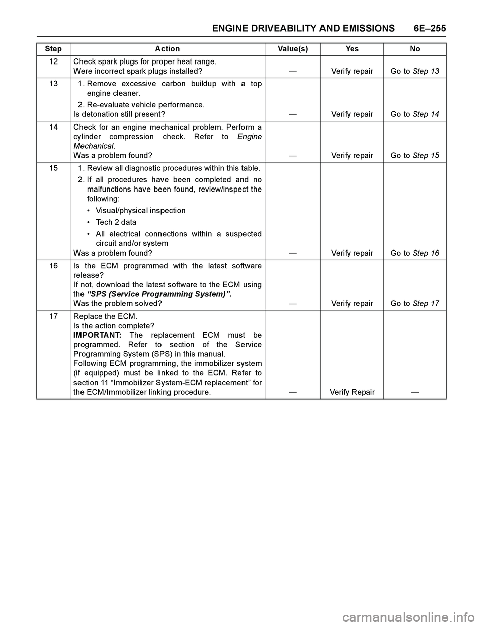
ENGINE DRIVEABILITY AND EMISSIONS 6E–255
12 Check spark plugs for proper heat range.
Were incorrect spark plugs installed?—Verify repair Go to Step 13
13 1. Remove ex cessive carbon buildup with a top
engine cleaner.
2. Re-evaluate vehicle performance.
Is detonation still present?—Verify repair Go to Step 14
14 Check for an engine mechanical problem. Perform a
cylinder compression check. Refer to Engine
Mechanical.
Was a problem found?—Verify repair Go to Step 15
15 1. Review all diagnostic procedures within this table.
2. If all procedures have been completed and no
malfunctions have been found, review/inspect the
followi ng:
Visual/physical inspection
Te c h 2 d a t a
All electrical connections within a suspected
circuit and/or system
Was a problem found?—Verify repair Go to Step 16
16 Is the ECM programmed with the latest software
release?
If not, download the latest software to the ECM using
the “SPS (Service Programming System)”.
Was the problem solved?—Verify repair Go to Step 17
17 Replace the ECM.
Is the action complete?
IMPORTANT: The replacement ECM must be
programmed. Refer to section of the Service
Programming System (SPS) in this manual.
Following ECM programming, the immobilizer system
(if equipped) must be linked to the ECM. Refer to
section 11 “Immobilizer System-ECM replacement” for
the ECM/Immobilizer linking procedure.—Verify Repair— Step Action Value(s) Yes No
Page 2833 of 4264
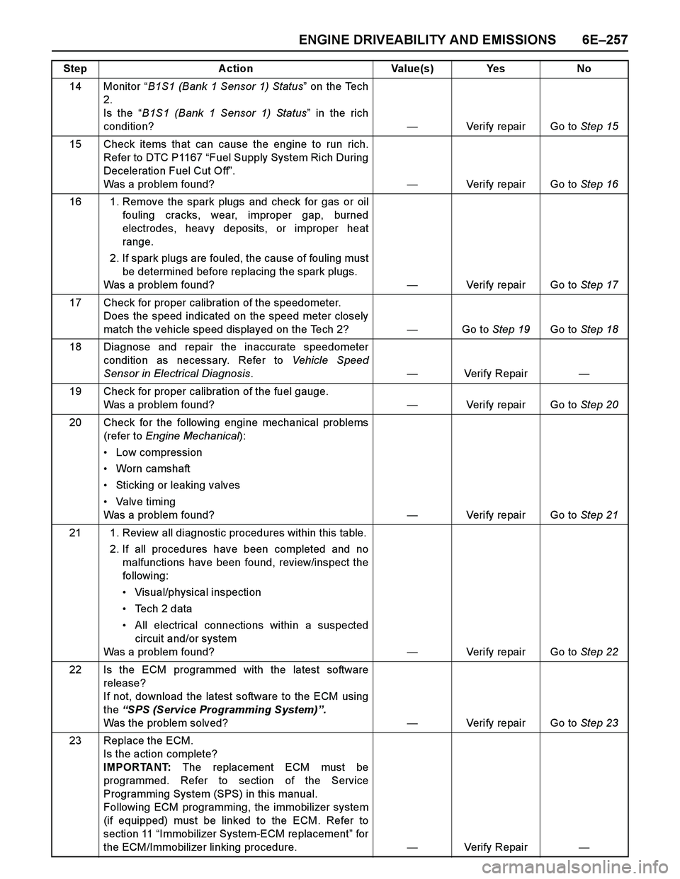
ENGINE DRIVEABILITY AND EMISSIONS 6E–257
14 Monitor “B1S1 (Bank 1 Sensor 1) Status” on the Tech
2.
Is the “B1S1 (Bank 1 Sensor 1) Status” in the rich
condition?—Verify repair Go to Step 15
15 Check items that can cause the engine to run rich.
Refer to DTC P1167 “Fuel Supply System Rich During
Deceleration Fuel Cut Off”.
Was a problem found?—Verify repair Go to Step 16
16 1. Remove the spark plugs and check for gas or oil
fouling cracks, wear, improper gap, burned
electrodes, heavy deposits, or improper heat
range.
2. If spark plugs are fouled, the cause of fouling must
be determined before replacing the spark plugs.
Was a problem found?—Verify repair Go to Step 17
17 Check for proper calibration of the speedometer.
Does the speed indicated on the speed meter closely
match the vehicle speed displayed on the Tech 2?—Go to Step 19Go to Step 18
18 Diagnose and repair the inaccurate speedometer
condition as necessary. Refer to Vehicle Speed
Sensor in Electrical Diagnosis.—Verify Repair—
19 Check for proper calibration of the fuel gauge.
Was a problem found?—Verify repair Go to Step 20
20 Check for the following engine mechanical problems
(refer to Engine Mechanical):
Low compression
Worn camshaft
Sticking or leaking valves
Valve timing
Was a problem found?—Verify repair Go to Step 21
21 1. Review all diagnostic procedures within this table.
2. If all procedures have been completed and no
malfunctions have been found, review/inspect the
followi ng:
Visual/physical inspection
Te c h 2 d a t a
All electrical connections within a suspected
circuit and/or system
Was a problem found?—Verify repair Go to Step 22
22 Is the ECM programmed with the latest software
release?
If not, download the latest software to the ECM using
the “SPS (Service Programming System)”.
Was the problem solved?—Verify repair Go to Step 23
23 Replace the ECM.
Is the action complete?
IMPORTANT: The replacement ECM must be
programmed. Refer to section of the Service
Programming System (SPS) in this manual.
Following ECM programming, the immobilizer system
(if equipped) must be linked to the ECM. Refer to
section 11 “Immobilizer System-ECM replacement” for
the ECM/Immobilizer linking procedure.—Verify Repair— Step Action Value(s) Yes No
Page 2837 of 4264
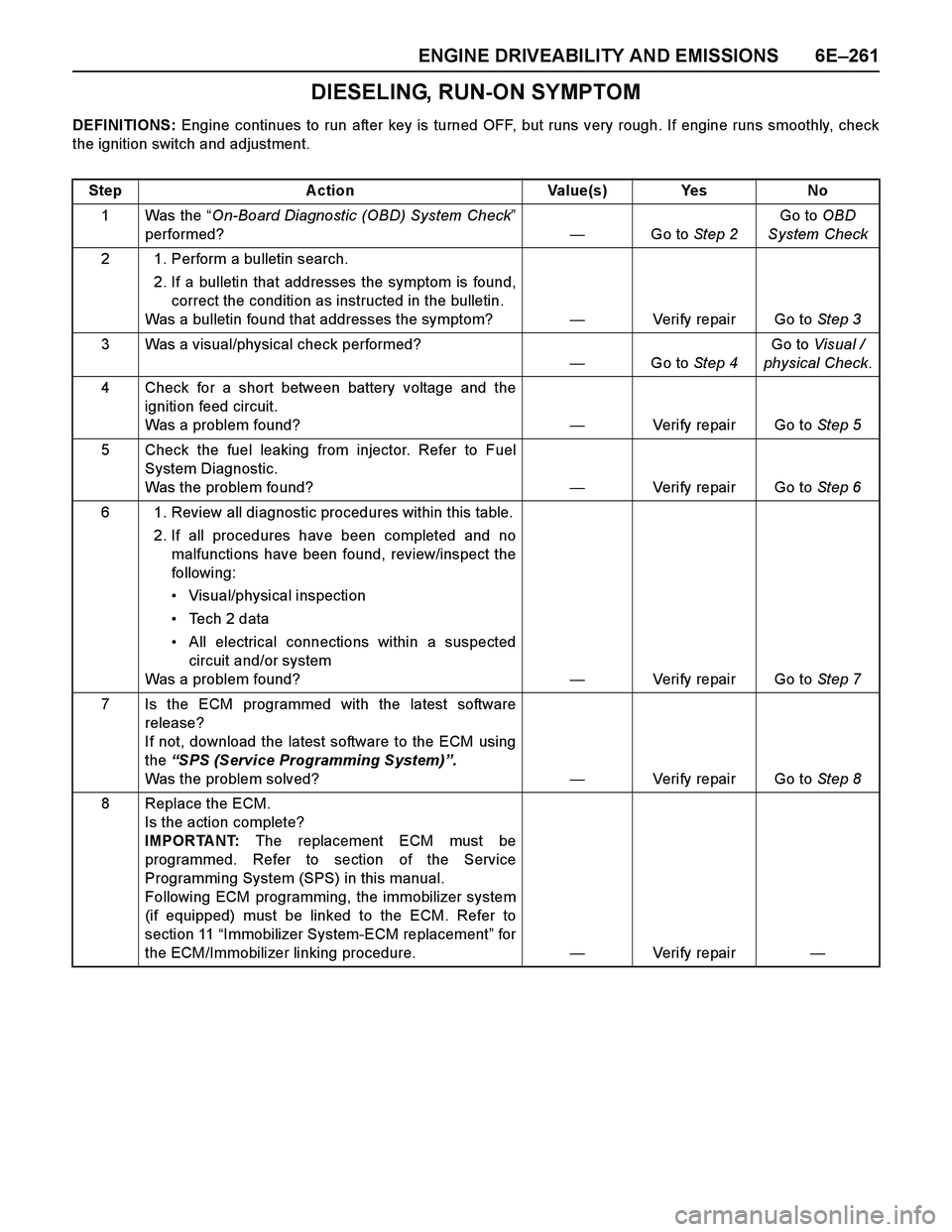
ENGINE DRIVEABILITY AND EMISSIONS 6E–261
DIESELING, RUN-ON SYMPTOM
DEFINITIONS: Engine continues to run after key is turned OFF, but runs very rough. If engine runs smoothly, check
the ignition switch and adjustment.
Step Action Value(s) Yes No
1Was the “On-Board Diagnostic (OBD) System Check”
performed?—Go to Step 2Go to OBD
System Check
2 1. Perform a bulletin search.
2. If a bulletin that addresses the symptom is found,
correct the condition as instructed in the bulletin.
Was a bulletin found that addresses the symptom?—Verify repair Go to Step 3
3 Was a visual/physical check performed?
—Go to Step 4Go to Visual /
physical Check.
4 Check for a short between battery voltage and the
ignition feed circuit.
Was a problem found?—Verify repair Go to Step 5
5 Check the fuel leaking from injector. Refer to Fuel
System Diagnostic.
Was the problem found?—Verify repair Go to Step 6
6 1. Review all diagnostic procedures within this table.
2. If all procedures have been completed and no
malfunctions have been found, review/inspect the
followi ng:
Visual/physical inspection
Te c h 2 d a t a
All electrical connections within a suspected
circuit and/or system
Was a problem found?—Verify repair Go to Step 7
7 Is the ECM programmed with the latest software
release?
If not, download the latest software to the ECM using
the “SPS (Service Programming System)”.
Was the problem solved?—Verify repair Go to Step 8
8 Replace the ECM.
Is the action complete?
IMPORTANT: The replacement ECM must be
programmed. Refer to section of the Service
Programming System (SPS) in this manual.
Following ECM programming, the immobilizer system
(if equipped) must be linked to the ECM. Refer to
section 11 “Immobilizer System-ECM replacement” for
the ECM/Immobilizer linking procedure.—Veri fy repai r—
Page 2839 of 4264
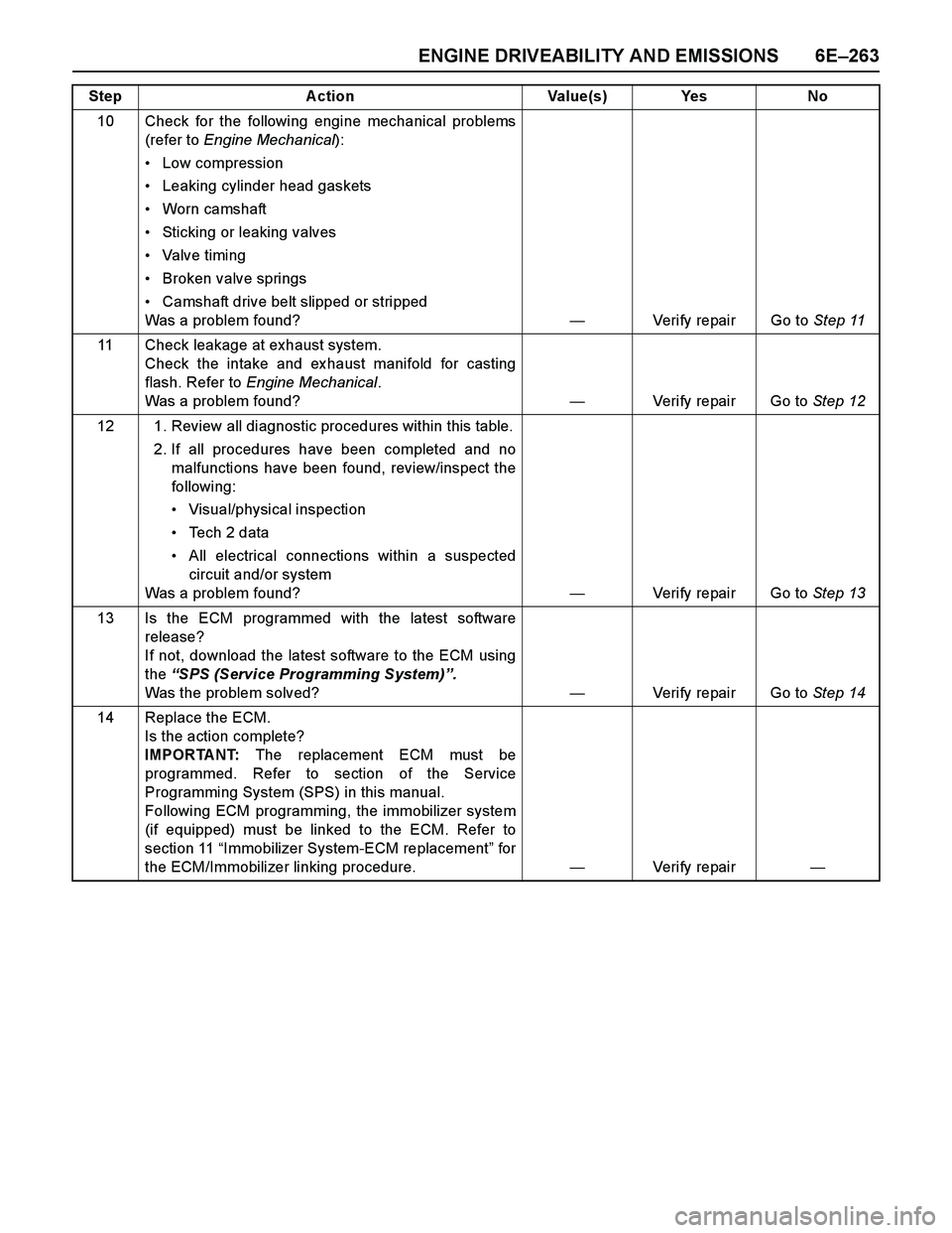
ENGINE DRIVEABILITY AND EMISSIONS 6E–263
10 Check for the following engine mechanical problems
(refer to Engine Mechanical):
Low compression
Leaking cylinder head gaskets
Worn camshaft
Sticking or leaking valves
Valve timing
Broken valve springs
Camshaft drive belt slipped or stripped
Was a problem found?—Verify repair Go to Step 11
11 Check leakage at exhaust system.
Check the intake and ex haust manifold for casting
flash. Refer to Engine Mechanical.
Was a problem found?—Verify repair Go to Step 12
12 1. Review all diagnostic procedures within this table.
2. If all procedures have been completed and no
malfunctions have been found, review/inspect the
followi ng:
Visual/physical inspection
Te c h 2 d a t a
All electrical connections within a suspected
circuit and/or system
Was a problem found?—Verify repair Go to Step 13
13 Is the ECM programmed with the latest software
release?
If not, download the latest software to the ECM using
the “SPS (Service Programming System)”.
Was the problem solved?—Verify repair Go to Step 14
14 Replace the ECM.
Is the action complete?
IMPORTANT: The replacement ECM must be
programmed. Refer to section of the Service
Programming System (SPS) in this manual.
Following ECM programming, the immobilizer system
(if equipped) must be linked to the ECM. Refer to
section 11 “Immobilizer System-ECM replacement” for
the ECM/Immobilizer linking procedure.—Veri fy repai r— Step Action Value(s) Yes No
Page 2893 of 4264
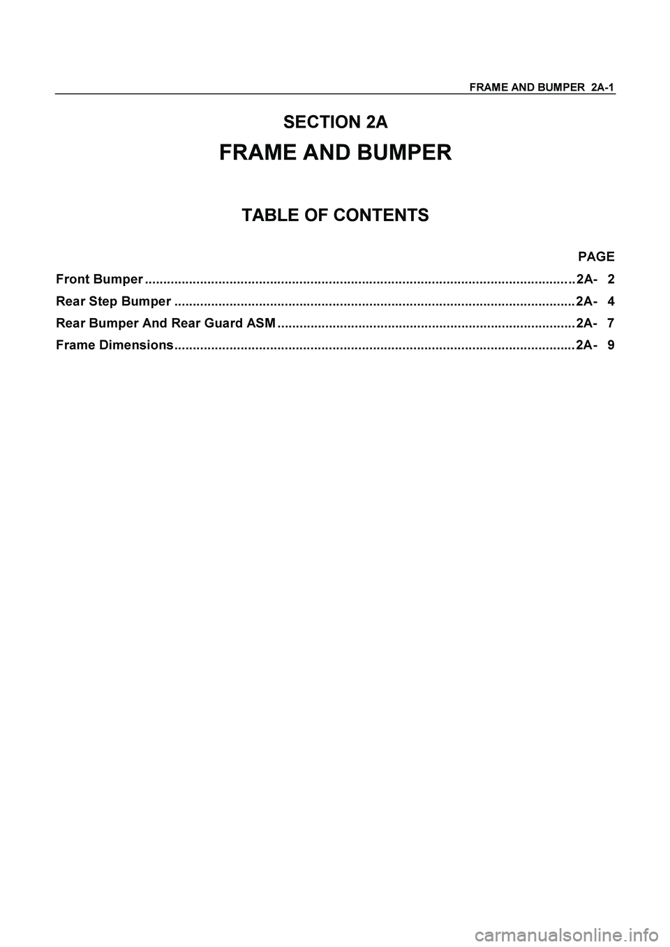
FRAME AND BUMPER 2A-1
SECTION 2A
FRAME AND BUMPER
TABLE OF CONTENTS
PAGE
Front Bumper ..................................................................................................................... 2A- 2
Rear Step Bumper ............................................................................................................. 2A- 4
Rear Bumper And Rear Guard ASM ................................................................................. 2A- 7
Frame Dimensions............................................................................................................. 2A- 9
Page 2933 of 4264

SHEET METAL 2B-1
SECTION 2B
SHEET METAL
This section includes items of front end sheet metal that are attached by bolts, screws or clips and related
accessory components.
Anticorrosion materials have been applied to the interior surfaces of some metal panels to provide rust resistance.
When servicing these panes, areas on which this material has been disturbed, should be properly recoated with
service-type anticorrosion material.
TABLE OF CONTENTS
PAGE
Engine Hood Assembly ..................................................................................................... 2B- 2
Engine Hood Lock ............................................................................................................. 2B- 5
Front Fender Panel ............................................................................................................ 2B- 7
Radiator Grille .................................................................................................................... 2B- 10
Rear Body ........................................................................................................................... 2B- 11
Body Mounting ................................................................................................................... 2B- 13
Body Dimension.................................................................................................................2B- 19
Page 2973 of 4264

GENERAL INFORMATION 0A-1
SECTION 0A
GENERAL INFORMATION
TABLE OF CONTENTS
PAGE
General Repair Instructions ............................................................................................ 0A- 2
Notes on The Format of this Manual .............................................................................. 0A- 3
Identification .................................................................................................................... 0A- 6
Lifting Instructions .......................................................................................................... 0A- 7
Conversion Table............................................................................................................. 0A- 9