section table ISUZU TF SERIES 2004 User Guide
[x] Cancel search | Manufacturer: ISUZU, Model Year: 2004, Model line: TF SERIES, Model: ISUZU TF SERIES 2004Pages: 4264, PDF Size: 72.63 MB
Page 659 of 4264
ELECTRICAL-BODY AND CHASSIS 8A-1
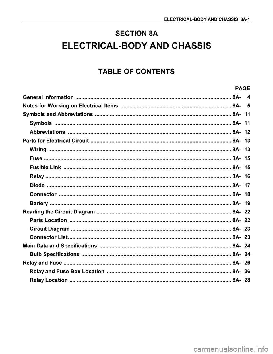
SECTION 8A
ELECTRICAL-BODY AND CHASSIS
TABLE OF CONTENTS
PAGE
General Information ........................................................................................................ 8A- 4
Notes for Working on Electrical Items .......................................................................... 8A- 5
Symbols and Abbreviations ........................................................................................... 8A- 11
Symbols ...................................................................................................................... 8A- 11
Abbreviations ............................................................................................................. 8A- 12
Parts for Electrical Circuit .............................................................................................. 8A- 13
Wiring .......................................................................................................................... 8A- 13
Fuse ............................................................................................................................. 8A- 15
Fusible Link ................................................................................................................ 8A- 15
Relay ............................................................................................................................ 8A- 16
Diode ........................................................................................................................... 8A- 17
Connector ................................................................................................................... 8A- 18
Battery ......................................................................................................................... 8A- 19
Reading the Circuit Diagram .......................................................................................... 8A- 22
Parts Location ............................................................................................................ 8A- 22
Circuit Diagram ........................................................................................................... 8A- 23
Connector List ............................................................................................................. 8A- 23
Main Data and Specifications ........................................................................................ 8A- 24
Bulb Specifications .................................................................................................... 8A- 24
Relay and Fuse ................................................................................................................ 8A- 26
Relay and Fuse Box Location ................................................................................... 8A- 26
Relay Location ............................................................................................................ 8A- 28
Page 1099 of 4264

CRUISE CONTROL SYSTEM 8B-1
SECTION 8B
CRUISE CONTROL SYSTEM
TABLE OF CONTENTS
PAGE
Service Precaution .........................................................................................................................8B- 3
General Description .......................................................................................................................8B- 3
Brake Switch ...................................................................................................................................8B- 5
Removal .......................................................................................................................................8B- 5
Installation ..................................................................................................................................8B- 5
Adjustment ..................................................................................................................................8B- 6
Clutch switch ...................................................................................................................................8B- 6
Removal and Installation ........................................................................................................8B- 6
Adjustment ..................................................................................................................................8B- 6
Starter Switch ..................................................................................................................................8B- 6
Removal .......................................................................................................................................8B- 6
Installation ..................................................................................................................................8B- 6
Cruise Control Main Switch .........................................................................................................8B- 7
Removal .......................................................................................................................................8B- 7
Installation ..................................................................................................................................8B- 7
Cruise Control Switch (Combination Switch) ........................................................................8B- 7
Removal and Installation ........................................................................................................8B- 7
Cruise Control Unit ........................................................................................................................8B- 8
Removal .......................................................................................................................................8B- 8
Installation ..................................................................................................................................8B- 8
Cruise Actuator ...............................................................................................................................8B- 8
Actuator Cable Diagram ..........................................................................................................8B- 9
Removal .......................................................................................................................................8B- 9
Installation ..................................................................................................................................8B- 9
Adjustment ..................................................................................................................................8B- 9
Mode Switch ....................................................................................................................................8B- 9
Removal and Installation ........................................................................................................8B- 9
Page 1121 of 4264
TROUBLESHOOTING 6 – 1
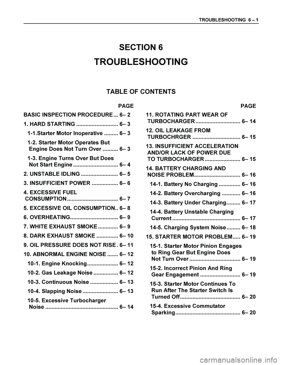
SECTION 6
TROUBLESHOOTING
TABLE OF CONTENTS
PAGE PAGE
BASIC INSPECTION PROCEDURE ... 6– 2
1. HARD STARTING ........................... 6– 3
1-1.Starter Motor Inoperative ......... 6– 3
1-2. Starter Motor Operates But
Engine Does Not Turn Over .......... 6– 3
1-3. Engine Turns Over But Does
Not Start Engine ............................. 6– 4
2. UNSTABLE IDLING ........................ 6– 5
3. INSUFFICIENT POWER ................. 6– 6
4. EXCESSIVE FUEL
CONSUMPTION ................................. 6– 7
5. EXCESSIVE OIL CONSUMPTION.. 6– 8
6. OVERHEATING............................... 6– 9
7. WHITE EXHAUST SMOKE ............. 6– 9
8. DARK EXHAUST SMOKE .............. 6– 10
9. OIL PRESSURE DOES NOT RISE . 6– 11
10. ABNORMAL ENGINE NOISE ....... 6– 12
10-1. Engine Knocking.................... 6– 12
10-2. Gas Leakage Noise ................ 6– 12
10-3. Continuous Noise .................. 6– 13
10-4. Slapping Noise ....................... 6– 13
10-5. Excessive Turbocharger
Noise ............................................... 6– 14
11. ROTATING PART WEAR OF
TURBOCHARGER ............................. 6– 14
12. OIL LEAKAGE FROM
TURBOCHRGER ............................... 6– 15
13. INSUFFICIENT ACCELERATION
AND/OR LACK OF POWER DUE
TO TURBOCHARGER ....................... 6– 15
14. BATTERY CHARGING AND
NOISE PROBLEM.............................. 6– 16
14-1. Battery No Charging .............. 6– 16
14-2. Battery Overcharging ............ 6– 16
14-3. Battery Under Charging......... 6– 17
14-4. Battery Unstable Charging
Current ............................................ 6– 17
14-5. Charging System Noise ......... 6– 18
15. STARTER MOTOR PROBLEM..... 6– 19
15-1. Starter Motor Pinion Engages
to Ring Gear But Engine Does
Not Turn Over ................................. 6– 19
15-2. Incorrect Pinion And Ring
Gear Engagement .......................... 6– 19
15-3. Starter Motor Continues To
Run After The Starter Switch Is
Turned Off ....................................... 6– 20
15-4. Excessive Commutator
Sparking .......................................... 6– 20
Page 1141 of 4264

ENGINE MECHANICAL 6A – 1
SECTION 6A
ENGINE MECHANICAL
TABLE OF CONTENTS
PAGE
Main Data and Specifications ....................................................................................... 6A - 4
Torque Specifications ................................................................................................... 6A - 8
Standard Bolts ........................................................................................................... 6A - 8
Special Parts Fixing Nuts and Bolts ........................................................................ 6A - 9
Recommended Liquid Gasket ...................................................................................... 6A - 22
LOCTITE Application Procedure .................................................................................. 6A - 23
Servicing......................................................................................................................... 6A - 24
Model Identification ................................................................................................... 6A - 24
Air Cleaner .................................................................................................................. 6A - 24
Lubricating System .................................................................................................... 6A - 24
Fuel System ................................................................................................................ 6A - 25
Cooling System .......................................................................................................... 6A - 27
Valve Clearance Adjustment ..................................................................................... 6A - 31
Compression Pressure Measurement ...................................................................... 6A - 32
General Description....................................................................................................... 6A- 36
Removal and Installation............................................................................................... 6A- 37
Removal ...................................................................................................................... 6A- 37
Installation .................................................................................................................. 6A- 40
Coolant Replenishment.......................................................................................... 6A- 41
Engine Warm-Up..................................................................................................... 6A- 41
Engine Repair Kit ........................................................................................................... 6A- 42
Engine Overhaul ............................................................................................................ 6A- 43
Removal ...................................................................................................................... 6A- 43
External Parts ......................................................................................................... 6A- 43
Page 1281 of 4264

ENGINE COOLING 6B – 1
SECTION 6B
ENGINE COOLING
TABLE OF CONTENTS
PAGE
Main Data and Specifications ....................................................................................... 6B - 3
General Description .................................................................................................. 6B - 4
Coolant Flow .............................................................................................................. 6B - 4
Water Pump................................................................................................................ 6B - 5
Thermostat ................................................................................................................. 6B - 5
Radiator ...................................................................................................................... 6B - 6
Diagnosis........................................................................................................................ 6B - 7
Draining and Refilling Cooling System ........................................................................ 6B - 8
Water Pump .................................................................................................................... 6B - 10
Removal and Installation .......................................................................................... 6B - 10
Removal...................................................................................................................... 6B - 10
Inspection and Repair ............................................................................................... 6B - 11
Installation.................................................................................................................. 6B - 11
Thermostat ..................................................................................................................... 6B - 13
Removal and Installation .......................................................................................... 6B - 13
Removal...................................................................................................................... 6B - 13
Inspection and Repair ............................................................................................... 6B - 13
Installation.................................................................................................................. 6B - 14
Radiator .......................................................................................................................... 6B - 15
Removal and Installation .......................................................................................... 6B - 15
Radiator and Associated Parts................................................................................. 6B - 15
Removal...................................................................................................................... 6B - 16
Inspection and Repair ............................................................................................... 6B - 17
Installation.................................................................................................................. 6B - 18
Page 1301 of 4264
FUEL SYSTEM 6C – 1
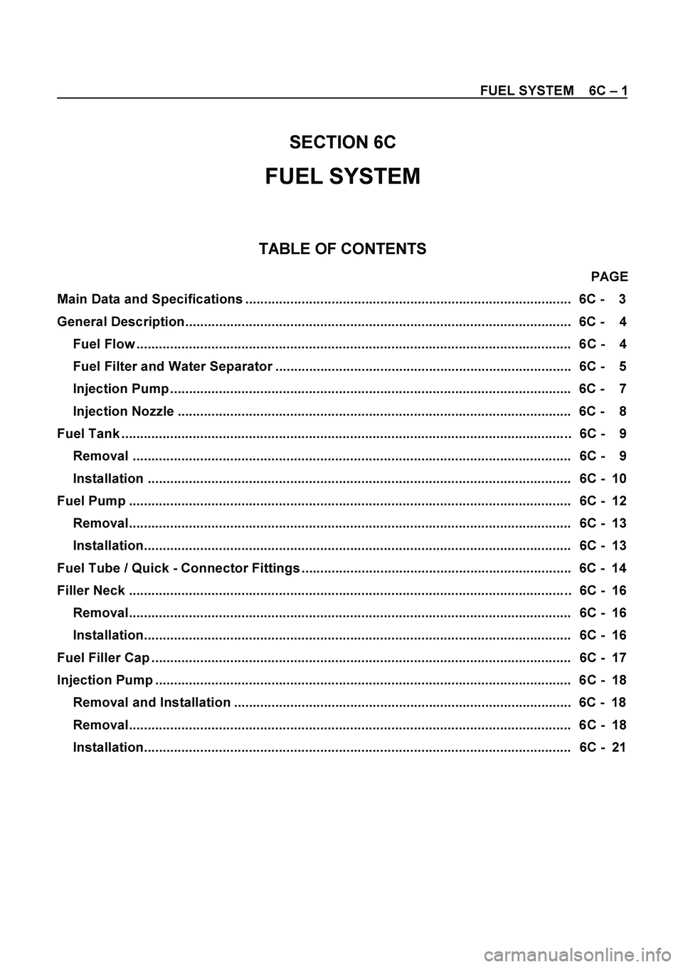
SECTION 6C
FUEL SYSTEM
TABLE OF CONTENTS
PAGE
Main Data and Specifications ....................................................................................... 6C - 3
General Description....................................................................................................... 6C - 4
Fuel Flow .................................................................................................................... 6C - 4
Fuel Filter and Water Separator ............................................................................... 6C - 5
Injection Pump ........................................................................................................... 6C - 7
Injection Nozzle ......................................................................................................... 6C - 8
Fuel Tank ........................................................................................................................ 6C - 9
Removal ..................................................................................................................... 6C - 9
Installation ................................................................................................................. 6C - 10
Fuel Pump ...................................................................................................................... 6C - 12
Removal...................................................................................................................... 6C - 13
Installation.................................................................................................................. 6C - 13
Fuel Tube / Quick - Connector Fittings ........................................................................ 6C - 14
Filler Neck ...................................................................................................................... 6C - 16
Removal...................................................................................................................... 6C - 16
Installation.................................................................................................................. 6C - 16
Fuel Filler Cap ................................................................................................................ 6C - 17
Injection Pump ............................................................................................................... 6C - 18
Removal and Installation .......................................................................................... 6C - 18
Removal...................................................................................................................... 6C - 18
Installation.................................................................................................................. 6C - 21
Page 1339 of 4264
ENGINE ELECTRICAL 6D – 1
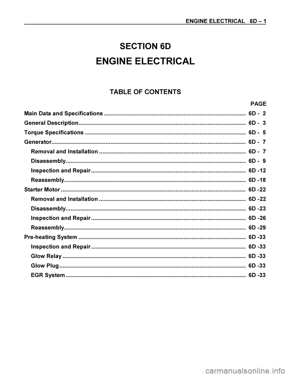
SECTION 6D
ENGINE ELECTRICAL
TABLE OF CONTENTS
PAGE
Main Data and Specifications ......................................................................................... 6D - 2
General Description......................................................................................................... 6D - 3
Torque Specifications ..................................................................................................... 6D - 5
Generator.......................................................................................................................... 6D - 7
Removal and Installation ............................................................................................ 6D - 7
Disassembly................................................................................................................. 6D - 9
Inspection and Repair ................................................................................................. 6D - 12
Reassembly.................................................................................................................. 6D - 18
Starter Motor .................................................................................................................... 6D - 22
Removal and Installation ............................................................................................ 6D - 22
Disassembly................................................................................................................. 6D - 23
Inspection and Repair ................................................................................................. 6D - 26
Reassembly.................................................................................................................. 6D - 29
Pre-heating System ......................................................................................................... 6D -33
Inspection and Repair ................................................................................................. 6D -33
Glow Relay ................................................................................................................... 6D -33
Glow Plug ..................................................................................................................... 6D -33
EGR System ................................................................................................................. 6D -33
Page 1442 of 4264
6E–70 4JA1/4JH1 ENGINE DRIVEABILITY AND EMISSIONS
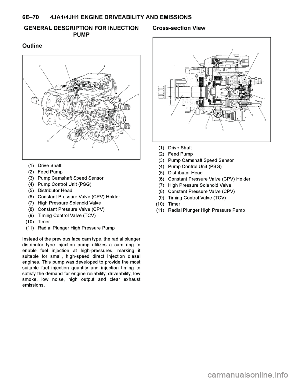
GENERAL DESCRIPTION FOR INJECTION
PUMP
Outline
Instead of the previous face cam type, the radial plunger
distributor type injection pump utilizes a cam ring to
enable fuel injection at high-pressures, marking it
suitable for small, high-speed direct injection diesel
engines. This pump was developed to provide the most
suitable fuel injection quantity and injection timing to
satisfy the demand for engine reliability, driveability, low
smoke, low noise, high output and clear ex haust
emissions.
Cross-section View
(1) Drive Shaft
(2) Feed Pump
(3) Pump Camshaft Speed Sensor
(4) Pump Control Unit (PSG)
(5) Distributor Head
(6) Constant Pressure Valve (CPV) Holder
(7) High Pressure Solenoid Valve
(8) Constant Pressure Valve (CPV)
(9) Timing Control Valve (TCV)
(10) Timer
(11) Radial Plunger High Pressure Pump
(1) Drive Shaft
(2) Feed Pump
(3) Pump Camshaft Speed Sensor
(4) Pump Control Unit (PSG)
(5) Distributor Head
(6) Constant Pressure Valve (CPV) Holder
(7) High Pressure Solenoid Valve
(8) Constant Pressure Valve (CPV)
(9) Timing Control Valve (TCV)
(10) Timer
(11) Radial Plunger High Pressure Pump
Page 1452 of 4264
6E–80 4JA1/4JH1 ENGINE DRIVEABILITY AND EMISSIONS
Step 3: Simulate the symptom and isolate the
problem
Simulate the symptom and isolate the system by
reproducing all possible conditions suggested in Step 1
while monitoring suspected circuits/components/
systems to isolate the problem symptom. Begin with the
most logical circuit/component.
Isolate the circuit by dividing the suspect system into
simpler circuits. Nex t, confine the problem into a smaller
area of the system. Begin at the most logical point (or
point of easiest access) and thoroughly check the
isolated circuit for the fault, using basic circuit tests.
Hints
You can isolate a circuit by:
Unplugging connectors or removing a fuse to
separate one part of the circuit from another
If only component fails to operate, begin testing the
component
If a number of components do not operate, begin test
at areas of commonality (such as power sources,
ground circuits, switches, main connectors or major
components)
Substitute a known good part from the parts
department or the vehicle system
Try the suspect part in a known good vehicle
See Symptom Simulation Tests on the nex t page for
problem simulation procedures. Refer to service manual
sections 6E and 8A for information about intermittent
diagnosis. Follow procedures for basic circuit testing in
service manual section 8A.
What resources you should use
Whenever appropriate, you should use the following
resources to assist in the diagnostic process:
Service manual
Bulletins
Digital multimeter (with a MIN/MAX feature)
Tech II and Tech II upload function
Circuit testing tools (including connector kits/
harnesses and jumper wires)
Ex perience
Intermittent problem solving simulation methods
Customer complaint check sheet
Symptom Simulation Tests
1. Vibration
This method is useful when the customer complaint
analysis indicates that the problem occurs when the
vehicle/system undergoes some form of vibration.
For connectors and wire harness, slightly shake
vertically and horizontally. Inspect the connector joint
and body for damage. Also, tapping lightly along a
suspected circuit may be helpful.For parts and sensors, apply slight vibration to the part
with a light tap of the finger while monitoring the system
for a malfunction.
2. Heat
This method is important when the complaint suggests
that the problem occurs in a heated environment. Apply
moderate heat to the component with a hair drier or
similar tool while monitoring the system for a
malfunction.
CA UTION: Care must be take to avoid overheating
the component.
3. Water and Moisture
This method may be used when the complaint suggests
that the malfunction occurs on a rainy day or under
conditions of high humidity. In this case, apply water in a
light spray on the vehicle to duplicate the problem.
CA UTION: Care must be take to avoid directly
exposing electrical connections to water.
4. Electrical loads
This method involves turning systems ON (such as the
blower, lights or rear window defogger) to create a load
on the vehicle electrical system at the same time you
are monitoring the suspect circuit/component.
5e. Vehicle Operates as Designed
This condition refers to instances where a system
operating as designed is perceived to be unsatisfactory
or undesirable. In general, this is due to:
A lack of understanding by the customer
A conflict between customer ex pectations and
vehicle design intent
A system performance that is unacceptable to the
customer
What you should do
You can verify that a system is operating as designed
by:
Reviewing service manual functional/diagnostic
checks
Ex amining bulletins and other service information for
supplementary information
Compare system operation to an identical vehicle
If the condition is due to a customer misunderstanding
or a conflict between customer ex pectation and system
operation, you should ex plain the system operation to
the customer.
If the complaint is due to a case of unsatisfactory
system performance, you should contact Technical
Assistance for the latest information.
What resources you should use
Whenever possible, you should use the following
resources to facilitate the diagnostic process:
Page 1733 of 4264

4JA1/4JH1 ENGINE DRIVEABILITY AND EMISSIONS 6E–361
SYMPTOM DIAGNOSIS
PRELIMINARY CHECKS
Before using this section, perform the “On-Board
Diagnostic (OBD) System Check” and verify all of the
following items:
The engine control module (ECM) and check engine
lamp (MIL=malfunction indicator lamp are operating
correctly.
There are no Diagnostic Trouble Code(s) stored.
Tech 2 data is within normal operating range. Refer to
Typical Scan Data Values.
Verify the customer complaint and locate the correct
symptom in the table of contents. Perform the
procedure included in the symptom chart.
VISUAL/PHYSICAL CHECK
Several of the symptom procedures call for a careful
visual/physical check. This can lead to correcting a
problem without further checks and can save valuable
time. This check should include the following items:
ECM grounds for cleanliness, tightness and proper
location.
Vacuum hoses for splits, kinks, and proper
connection. Check thoroughly for any type of leak or
restriction.
Air intake ducts for collapsed or damaged areas.
Air leaks at throttle body mounting area, mass air flow
(MAF) sensor and intake manifold sealing surfaces.
Wiring for proper connections, pinches and cuts.
INTERMITTENT
Important: An intermittent problem may or may not turn
on the check engine lamp (MIL=malfunction indicator
lamp) or store a Diagnostic Trouble Code. Do NOT use
the Diagnostic Trouble Code (DTC) charts for
intermittent problems.
The fault must be present to locate the problem.
Most intermittent problems are cased by faulty electrical
connections or wiring. Perform a careful visual/physical
check for the following conditions.
Poor mating of the connector halves or a terminal not
fully seated in the connector (backed out).
Improperly formed or damaged terminal.
All connector terminals in the problem circuit should
be carefully checked for proper contact tension.
Poor terminal-to-wire connection. This requires
removing the terminal form the connector body to
check.
Check engine lamp (MIL=malfunction indicator lamp)
wire to ECM shorted to ground.
Poor ECM grounds. Refer to the ECM wiring
diagrams.Road test the vehicle with a Digital Multimeter
connected to a suspected circuit. An abnormal voltage
when the malfunction occurs is a good indication that
there is a fault in the circuit being monitored.
Using Tech 2 to help detect intermittent conditions. The
Tech 2 have several features that can be used to
located an intermittent condition. Use the following
features to find intermittent faults:
To check for loss of diagnostic code memory,
disconnect the MAF sensor and idle the engine until the
check engine lamp (MIL=malfunction indicator lamp)
comes on. Diagnostic Trouble Code P0100 should be
stored and kept in memory when the ignition is turned
OFF.
If not, the ECM is faulty. When this test is completed,
make sure that you clear the Diagnostic Trouble Code
P0100 from memory.
An intermittent check engine lamp (MIL=malfunction
indicator lamp) with no stored Diagnostic Trouble Code
may be caused by the following:
Check engine lamp (MIL=malfunction indicator lamp)
wire to ECM short to ground.
Poor ECM grounds. Refer to the ECM wiring
diagrams.
Check for improper installation of electrical options such
as light, cellular phones, etc. Check all wires from ECM
to the ignition control module for poor connections.
Check for an open diode across the A/C compressor
clutch and check for other open diodes (refer to wiring
diagrams in Electrical Diagnosis).
If problem has not been found, refer to ECM connector
symptom tables.
Check the “Broadcast Code” of the ECM, and
compare it with the latest Isuzu service bulletins and/
or Isuzu EEPROM reprogramming equipment to
determine if an update to the ECM's reprogrammable
memory has been released.
This identifies the contents of the reprogrammable
software and calibration contained in the ECM.
If the “Broadcast Code” is not the most current
available, it is advisable to reprogram the ECM's
EEPROM memory, which may either help identify a
hard-to find problem or may fix the problem.
The Service Programming System (SPS) will not allow
incorrect software programming or incorrect calibration
changes.