engine ISUZU TF SERIES 2004 Manual Online
[x] Cancel search | Manufacturer: ISUZU, Model Year: 2004, Model line: TF SERIES, Model: ISUZU TF SERIES 2004Pages: 4264, PDF Size: 72.63 MB
Page 1091 of 4264

ELECTRICAL-BODY AND CHASSIS 8A-433
No. Connector face No. Connector face
H-1
White
Battery (+) ~ Engine room H-10
WhiteINST ~ Front Door-RH
H-2
NOT USED H-11
NOT USED
H-3
(6VE1,
4JH1-TC)
White Battery (+) ~ Engine room H-12
BlackINST ~ Roof
H-4
(C24SE)
White Engine room ~ Mission H-13
WhiteINST ~ Door -LH
H-4
(6VE1,
4JA1-TC,
4JH1-TC)
White
Engine ~ Engine room H-14
WhiteRear body ~ Rear door-LH
H-5
NOT USED H-15
White
Engine room ~ Chassis
H-6
White
Engine room ~ INST H-16
WhiteRear body ~ Rear door-RH
H-7
White
Engine room ~ INST H-17
WhiteChassis ~ License plate lamp
H-8
NOT USED H-18
White
Engine room ~ INST
H-9
Blue
Engine room ~ Chassis H-19
~
H-21 NOT USED
Page 1092 of 4264

8A-434 ELECTRICAL-BODY AND CHASSIS
No. Connector face No. Connector face
H-22
(6VE1)
(4JH1-TC)
White Engine ~ Engine room C H-31
(C24SE)
Engine room ~ Mission
H-23
(6VE1)
(4JH1-TC)
White Engine ~ Engine room B H-32
(C24SE)
(6VE1)
Engine room ~ Rear body
H-23
(4JA1-L)
White Engine room B ~ T/misson H-33
(4JH1-TC)
Engine ~ Engine room
H-24
Black
INST ~ Front door-RH H-34
(C24SE)
Engine ~ Engine room
H-25
Black
INST ~ Front door-LH H-35
Trailer
H-26
White
INST ~ Rear body
H-27
Black
INST ~ Rear body
H-28
White
Sub harness connector
H-29
(C24SE)
Battery(+) ~ Engine room
H-30
(6VE1)
(4JH1-TC)
Engine room ~ INST
Page 1095 of 4264

ELECTRICAL-BODY AND CHASSIS 8A-437
No. Connector face No. Connector face
P-1
Silver
Battery (+) P-9
SilverACG (B)
P-2
Silver
Relay & Fuse box P-10
SilverEngine ground
P-3
Brown
Starter (S) P-11
SilverFuse & relay box
P-4
Silver
Starter (B) P-12
NOT USED
P-4
Silver
Starter (B) P-13
Gray Shift on the fly actuator
P-5
Silver
Battery (-) P-14
WhiteFuse & relay box
P-6
Silver
Body earth (Ground) P-15
Silver2nd battery (+)
P-7
NOT USED P-16
Silver
2nd battey (-)
P-8
(C24SE)
(4JH1-TC
Green ACG (L)
P-8
(6VE1)
White ACG (L)
Page 1115 of 4264

CRUISE CONTROL SYSTEM 8B-17
DTC 2–1 Signal of Vehicle Speed Malfunction
Step Action Value(s) YES NO
1 Check the DTC for engine.
Is the vehicle speed sensor DTC set?
—
Go to DTC for
engine
Go to Step 2
2 Check continuity between harness side connector
E–44 terminal 3 and connector C–120 terminal 9.
Is there continuity between terminals?
—
Go to Step 3
Replace open
circuit
3 Check the continuity between harness side
connector E–44 terminal 3 and ground, connector
C–120 terminal 9 and ground.
Are the results same as specified in the value(s)
column?
No continuity
Replace the
control unit
Repair short
circuit
Page 1119 of 4264

WORKSHOP MANUAL
TF SERIES
ENGINE
4JA1/4JH1-TC
SECTION 6
Page 1121 of 4264

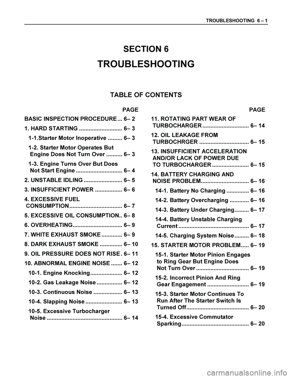
TROUBLESHOOTING 6 – 1
SECTION 6
TROUBLESHOOTING
TABLE OF CONTENTS
PAGE PAGE
BASIC INSPECTION PROCEDURE ... 6– 2
1. HARD STARTING ........................... 6– 3
1-1.Starter Motor Inoperative ......... 6– 3
1-2. Starter Motor Operates But
Engine Does Not Turn Over .......... 6– 3
1-3. Engine Turns Over But Does
Not Start Engine ............................. 6– 4
2. UNSTABLE IDLING ........................ 6– 5
3. INSUFFICIENT POWER ................. 6– 6
4. EXCESSIVE FUEL
CONSUMPTION ................................. 6– 7
5. EXCESSIVE OIL CONSUMPTION.. 6– 8
6. OVERHEATING............................... 6– 9
7. WHITE EXHAUST SMOKE ............. 6– 9
8. DARK EXHAUST SMOKE .............. 6– 10
9. OIL PRESSURE DOES NOT RISE . 6– 11
10. ABNORMAL ENGINE NOISE ....... 6– 12
10-1. Engine Knocking.................... 6– 12
10-2. Gas Leakage Noise ................ 6– 12
10-3. Continuous Noise .................. 6– 13
10-4. Slapping Noise ....................... 6– 13
10-5. Excessive Turbocharger
Noise ............................................... 6– 14
11. ROTATING PART WEAR OF
TURBOCHARGER ............................. 6– 14
12. OIL LEAKAGE FROM
TURBOCHRGER ............................... 6– 15
13. INSUFFICIENT ACCELERATION
AND/OR LACK OF POWER DUE
TO TURBOCHARGER ....................... 6– 15
14. BATTERY CHARGING AND
NOISE PROBLEM.............................. 6– 16
14-1. Battery No Charging .............. 6– 16
14-2. Battery Overcharging ............ 6– 16
14-3. Battery Under Charging......... 6– 17
14-4. Battery Unstable Charging
Current ............................................ 6– 17
14-5. Charging System Noise ......... 6– 18
15. STARTER MOTOR PROBLEM..... 6– 19
15-1. Starter Motor Pinion Engages
to Ring Gear But Engine Does
Not Turn Over ................................. 6– 19
15-2. Incorrect Pinion And Ring
Gear Engagement .......................... 6– 19
15-3. Starter Motor Continues To
Run After The Starter Switch Is
Turned Off ....................................... 6– 20
15-4. Excessive Commutator
Sparking .......................................... 6– 20
Page 1122 of 4264

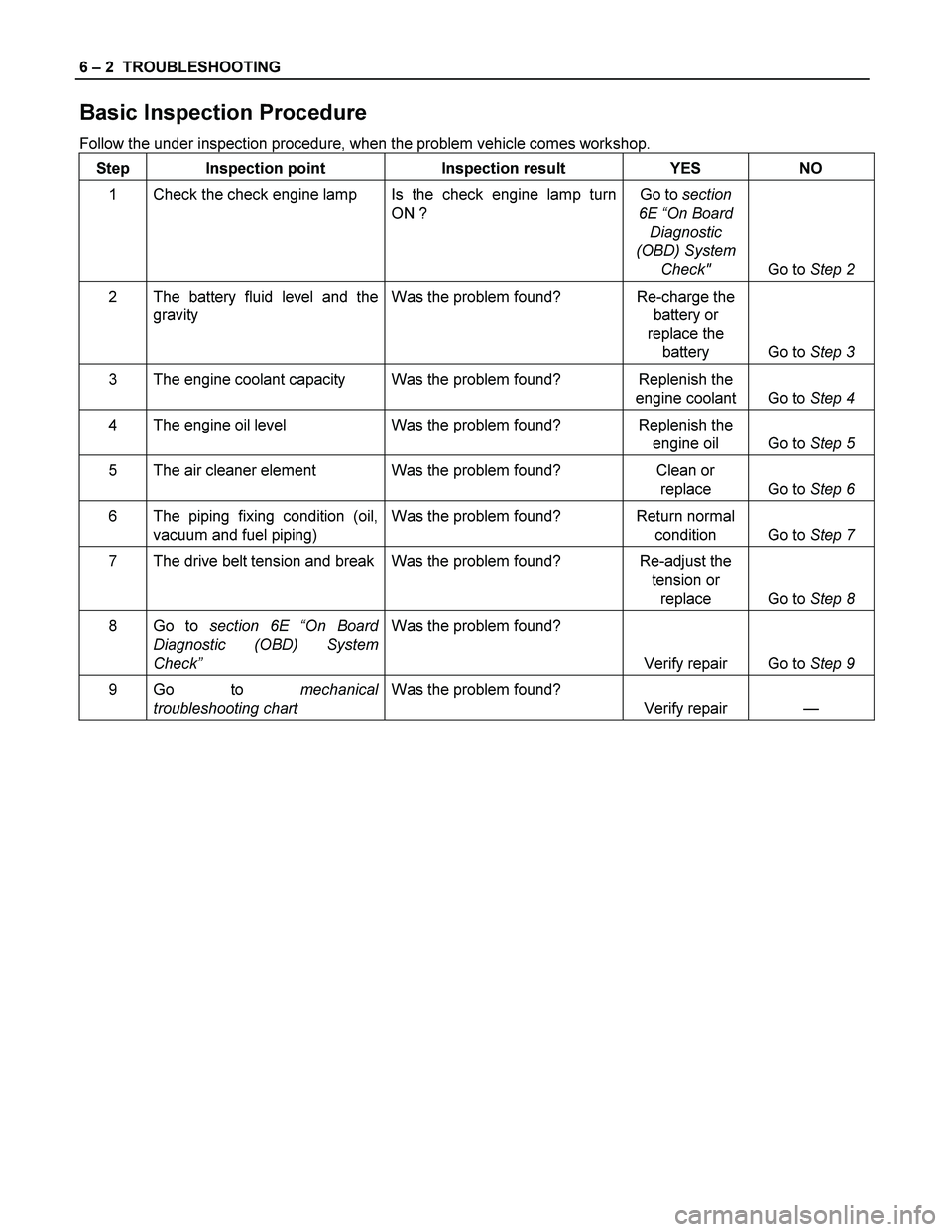
6 – 2 TROUBLESHOOTING
Basic Inspection Procedure
Follow the under inspection procedure, when the problem vehicle comes workshop.
Step Inspection point Inspection result YES NO
1 Check the check engine lamp Is the check engine lamp turn
ON ? Go to section
6E “On Board
Diagnostic
(OBD) System
Check" Go to Step 2
2 The battery fluid level and the
gravity Was the problem found? Re-charge the
battery or
replace the
battery Go to Step 3
3 The engine coolant capacity Was the problem found? Replenish the
engine coolant Go to Step 4
4 The engine oil level Was the problem found? Replenish the
engine oil Go to Step 5
5 The air cleaner element Was the problem found? Clean or
replace Go to Step 6
6 The piping fixing condition (oil,
vacuum and fuel piping) Was the problem found? Return normal
condition Go to Step 7
7 The drive belt tension and break Was the problem found? Re-adjust the
tension or
replace Go to Step 8
8 Go to section 6E “On Board
Diagnostic (OBD) System
Check” Was the problem found?
Verify repair Go to Step 9
9 Go to mechanical
troubleshooting chart Was the problem found?
Verify repair —
Page 1123 of 4264

TROUBLESHOOTING 6 – 3
1. Hard Starting
Inspect the following items before diagnosis.
1. The battery conditions.
The terminal connection condition.
The battery charge condition or battery power weakness.
2. The fan belt loosen or broken.
3. The main fuse condition (open or not).
4. Fuel quantity level.
1–1 Starter motor inoperative
Step Action Value(s) Yes No
1 Check the starter switch.
Does the starter switch work? —
Go to Step 2 Repair or
replace the
starter switch
2 Check the starter relay.
Does the starter relay work? —
Go to Step 3 Repair or
replace the
starter relay
3 Check the magnetic switch.
Does the magnetic switch work? —
Go to Step 4 Repair or
replace the
magnetic
switch
4 Check the pinion gear condition on the starter motor.
Was the condition normal? —
Go to Step 5 Replace the
pinion gear
5 Check the brush wear or brush spring weakness.
Was the condition normal? —
Replace the
starter motor
assembly Repair or
replace the
brush or brush
spring
1-2 Starter motor operates but engine does not turn over
Step Action Value(s) Yes No
1 Check the engine internal seizure.
Was the engine seized? —
Repair or
replace seized
parts Check other
DTC by Tech
2 and go to
indicated DTC
Page 1124 of 4264

6 – 4 TROUBLESHOOTING
1-3 Engine turn over but does not start engine
Incase of the fuel not being delivered to the injection pump
Step Action Value(s) Yes No
1 Check clogged, damaged the fuel piping or the
connector loosen.
Was any problem found? —
Repair replace
problem parts. Go to Step 2
2 Was the over flow valve on the fuel filter closed? — Repair replace
the over flow
valve Go to Step 3
3 Was the fuel filter element clogged? — Replace the
fuel filter
element Go to Step 4
4 Was the fuel line air bled? — Go to Step 5 Bleed the air
5 Are any DTC stored? — Go to indicated
DTC Solved
Incase of the fuel is being delivered to the injection pump
Step Action Value(s) Yes No
1 Was the water contain in the fuel? — Replace the
fuel Go to Step 2
2 Was the fuel line air bled? — Go to Step 5 Bleed the air
3 Was the injection spray condition complete? —
Go to Step 4 Replace the
injection nozzle
4 Was the injection nozzle injection starting pressure
OK? (See below)
Go to Step 5 Replace the
injection nozzle
5 Was the injection nozzle sticking? — Replace the
injection nozzle Go to Step 6
6 Are any DTC stored? — Go to indicated
DTC Solved
Injection nozzle opening pressure
1st = 19.5 MPa (199 kg/cm2, 2828 psi)
Page 1129 of 4264

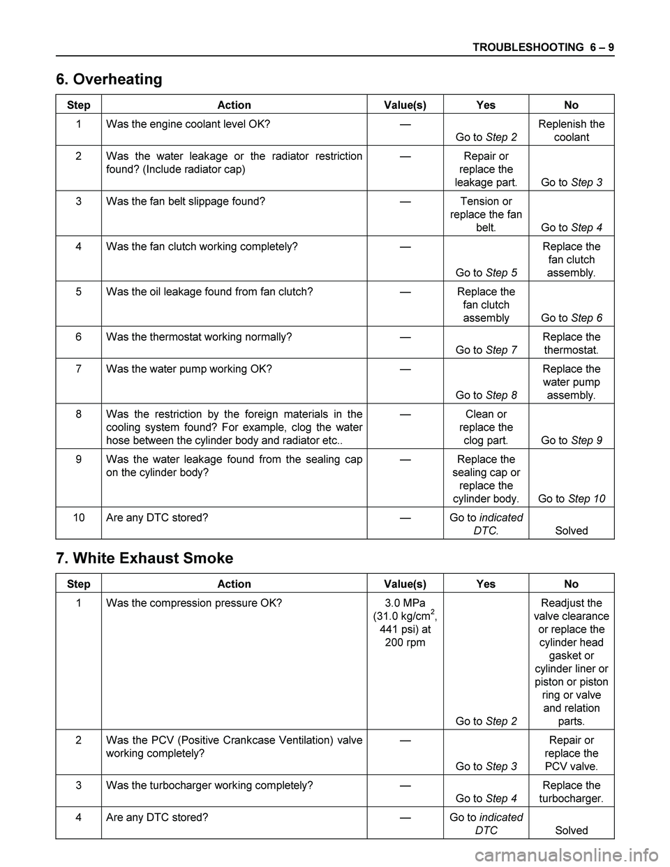
TROUBLESHOOTING 6 – 9
6. Overheating
Step Action Value(s) Yes No
1 Was the engine coolant level OK? —
Go to Step 2 Replenish the
coolant
2 Was the water leakage or the radiator restriction
found? (Include radiator cap) — Repair or
replace the
leakage part. Go to Step 3
3 Was the fan belt slippage found? — Tension or
replace the fan
belt. Go to Step 4
4 Was the fan clutch working completely? —
Go to Step 5 Replace the
fan clutch
assembly.
5 Was the oil leakage found from fan clutch? — Replace the
fan clutch
assembly Go to Step 6
6 Was the thermostat working normally? —
Go to Step 7 Replace the
thermostat.
7 Was the water pump working OK? —
Go to Step 8 Replace the
water pump
assembly.
8 Was the restriction by the foreign materials in the
cooling system found? For example, clog the water
hose between the cylinder body and radiator etc.. — Clean or
replace the
clog part. Go to Step 9
9 Was the water leakage found from the sealing cap
on the cylinder body? — Replace the
sealing cap or
replace the
cylinder body. Go to Step 10
10 Are any DTC stored? — Go to indicated
DTC. Solved
7. White Exhaust Smoke
Step Action Value(s) Yes No
1 Was the compression pressure OK? 3.0 MPa
(31.0 kg/cm2,
441 psi) at
200 rpm
Go to Step 2 Readjust the
valve clearance
or replace the
cylinder head
gasket or
cylinder liner or
piston or piston
ring or valve
and relation
parts.
2 Was the PCV (Positive Crankcase Ventilation) valve
working completely? —
Go to Step 3 Repair or
replace the
PCV valve.
3 Was the turbocharger working completely? —
Go to Step 4 Replace the
turbocharger.
4 Are any DTC stored? — Go to indicated
DTC Solved