check oil ISUZU TF SERIES 2004 Workshop Manual
[x] Cancel search | Manufacturer: ISUZU, Model Year: 2004, Model line: TF SERIES, Model: ISUZU TF SERIES 2004Pages: 4264, PDF Size: 72.63 MB
Page 31 of 4264
SUPPLEMENTAL RESTRAINT SYSTEM 9A-11
“Continuous Monitoring”
Tests performed by the SRS control unit on the SRS
every 100 milliseconds while “Ignition 1” voltage is in
the normal operating voltage range at the SRS control
unit.
Data Link Connector (DLC)
Formerly “DLC” a connector which allows
communication with an external computer, such as a
scan tool.
Datum Line
A base line parallel to the plane of the underbody or
frame from which all vertical measurements originate.
Deploy
To inflate the air bag.
Deployment Loops
The circuits which supply current to the air bag
assemblies to deploy the air bag.
Diagnostic Trouble Code (DTC)
Formerly “Code”, a numerical designator used by the
SRS control unit to indicate specific SRS malfunctions.
Driver Current Source
An output of the SRS control unit which applies current
into the driver air bag assembly circuit during the
“Initiator Assembly Resistance Test”.
“Initiator Assembly Resistance Test”
Tests performed once each ignition cycle when no
malfunctions are detected during “Turn–ON” or
“Continuous Monitoring”. This test checks for the
correct SRS control unit configuration for the vehicle,
shorts to “Ignition 1” in the deployment loops, high
resistance or opens in the “Driver Side” and
“Passenger Side” circuits and measures the resistance
of the inflator assembly consisting of 1) Initiators, 2)
SRS coil assembly (driver side only), 3) Connectors
and associated wiring.
Normal Operating Voltage Range
The voltage measured between the SRS control unit
“Ignition 1” terminals and “Ground” terminals is
between 9 and 16 volts.
Passenger Current Source
An output of the SRS control unit which applies current
into the passenger air bag assembly circuit during the
“Initiator Assembly Resistance Test”.
Passenger Air Bag Assembly
An assembly located in the front of the passenger side
of the instrument panel consisting of an inflatable bag,
an inflator and an initiator.
Scan Tool
An external computer used to read diagnostic
information from on–board computers via the data link
connector.
SRS control unit
SRS control unit which provides reserve energy to the
deployment loops, deploys the air bags when required
and performs diagnostic monitoring of all SRS
components.
Serial Data
Information representing the status of the SRS.
SRS
Supplemental Restraint System.
SRS Coil Assembly
An assembly of two current–carrying coils in the driver
deployment loop that allows the rotation of the steering
wheel while maintaining the continuous contact of the
driver deployment loop to the driver air bag assembly.
SRS Wiring Harness
The wires and connectors that electrically connect the
components in the SRS.
“Turn–ON”
Test which the SRS control unit performs on the SRS
once during each ignition cycle immediately after
“Ignition 1” voltage is applied to the SRS control unit
and before “Continuous Monitoring”.
Page 48 of 4264
9A-28 SUPPLEMENTAL RESTRAINT SYSTEM
– Driver air bag assembly
– Passenger air bag assembly
– Steering wheel
– SRS coil assembly
– Steering column
– Knee bolster and instrument panel mounting
attachments
– Driver seat and belt
– Passenger seat and belt
– SRS control unit
SRS control unit always should be checked according
to “SRS Control Unit Replacement Guidelines.”
CAUTION: Refer to “SRS control unit Replacement
Guidelines” below for important information on
SRS control unit replacement in both deployment
and non–deployment crashes.
Inspect SRS coil assembly wiring and steering wheel
for any sign of scorching, melting, or damage due to
excessive heat. If coil assembly wire or steering wheel
is damaged, replace them. The steering column and
wheel must be dimensionally checked to determine if
they are damaged. Refer to steering wheel of in this
manual.
Never use SRS parts from another vehicle. This does
not include remanufactured parts purchased from an
authorized Isuzu Retailer; they may be used for SRS
repairs.
Do not attempt to repair the SRS control unit, the SRS
harness, the SRS coil assembly, the air bag assembly,
the steering wheel, or the steering column. Service of
these items is replacement only. Verify replacement
part numbers.
CAUTION: Proper operation of the SRS control
unit and supplemental restraint system (SRS)
requires that any repairs to the vehicle structure
return it to its original production configuration.
SRS Connectors
CAUTION: The special yellow color connectors are
used for supplemental restraint system-air bag
circuit. When removing the cable harness, do not
pull the cables otherwise, cable disconnection
may occur. When connect the SRS connector,
insert the connector completely. Imperfect locking
may cause malfunction of SRS circuit.
Removal
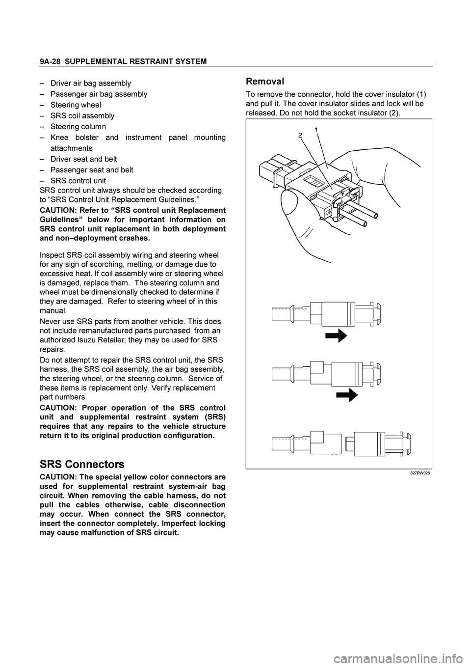
To remove the connector, hold the cover insulator (1)
and pull it. The cover insulator slides and lock will be
released. Do not hold the socket insulator (2).
827RW028
Page 52 of 4264
9A-32 SUPPLEMENTAL RESTRAINT SYSTEM
Driver Air Bag Assembly
Service Precautions
WARNING: SAFETY PRECAUTIONS MUST BE
FOLLOWED WHEN HANDLING A DEPLOYED AI
R
BAG ASSEMBLY. AFTER DEPLOYMENT, THE AIR
BAG ASSEMBLY SURFACE MAY CONTAIN A
SMALL AMOUNT OF SODIUM HYDROXIDE, A BY–
PRODUCT OF THE DEPLOYMENT REACTION,
THAT IS IRRITATING TO THE SKIN AND EYES.
MOST OF THE POWER ON THE AIR BAG
ASSEMBLY IS HARMLESS. AS A PRECAUTION,
WEAR GLOVES AND SAFETY GLASSES WHEN
HANDLING A DEPLOYED AIR BAG ASSEMBLY,
AND WASH YOUR HANDS WITH MILD SOAP AND
WATER AFTERWARDS.
WARNING: WHEN CARRYING A LIVE AIR BAG
ASSEMBLY, MAKE SURE THE BAG AND TRIM
COVER ARE POINTED AWAY FROM YOU. NEVE
R
CARRY AIR BAG ASSEMBLY BY THE WIRES OR
CONNECTOR ON THE UNDERSIDE OF MODULE.
IN THE CASE OF AN ACCIDENTAL DEPLOYMENT,
THE BAG WILL THEN DEPLOY WITH MINIMAL
CHANCE OF INJURY. WHEN PLACING ALIVE AI
R
BAG ASSEMBLY ON A BENCH OR OTHER
SURFACE, ALWAYS FACE BAG AND TRIM COVER
UP, AWAY FROM THE SURFACE. NEVER REST A
STEERING COLUMN ASSEMBLY ON THE
STEERING WHEEL WITH THE AIR BAG
ASSEMBLY FACE DOWN AND COLUMN
VERTICAL. THIS IS NECESSARY SO THAT A FREE
SPACE IS PROVIDED TO ALLOW THE AIR BAG
ASSEMBLY TO EXPAND IN THE UNLIKELY EVENT
OF ACCIDENTAL DEPLOYMENT. OTHERWISE,
PERSONAL INJURY COULD RESULT.
NOTE: In the event deployment has occurred, inspec
t
coil assembly wire for any signs of scorching, melting
or any other damage due to excessive heat. If the coil
has been damaged, replace it.
Removal
1. Disable the SRS (Refer to “Disabling the SRS” in
this section).
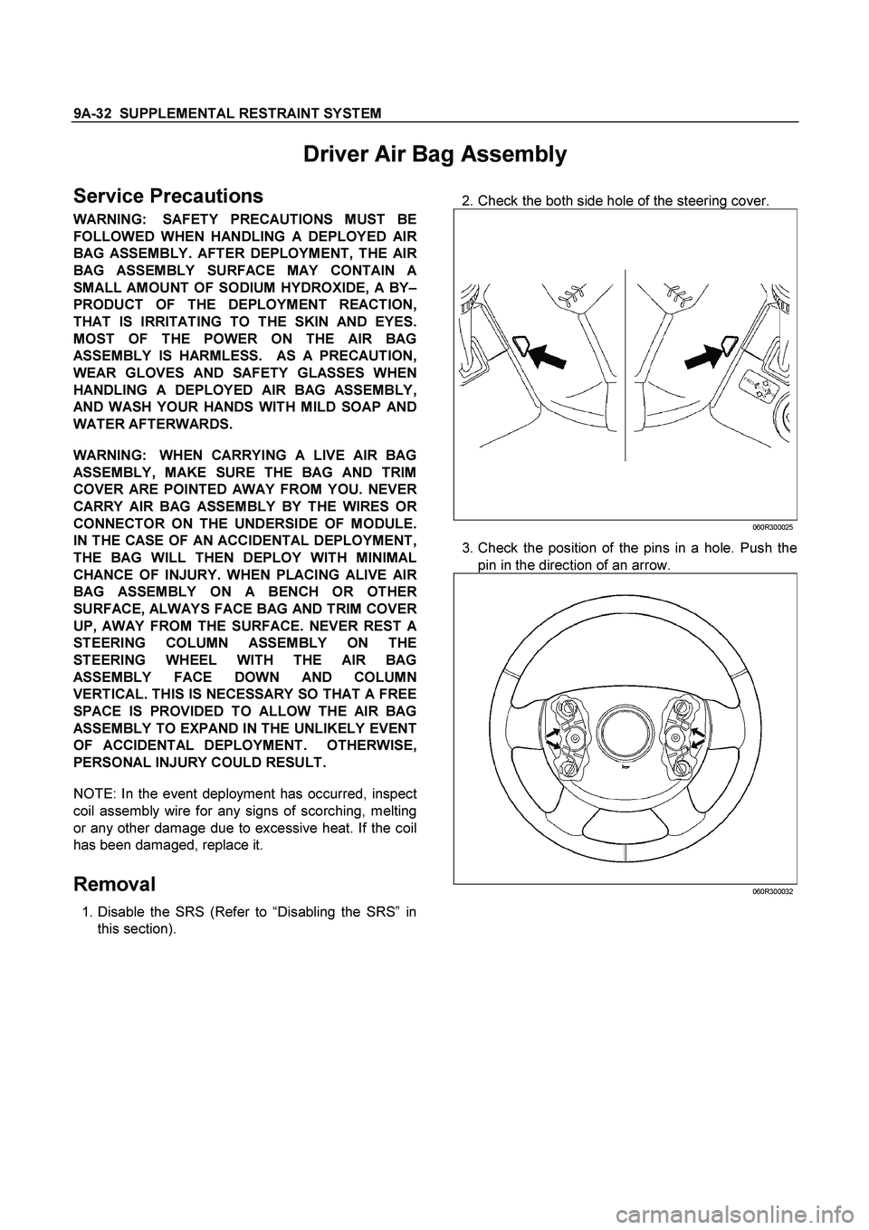
2. Check the both side hole of the steering cover.
060R300025
3. Check the position of the pins in a hole. Push the
pin in the direction of an arrow.
060R300032
Page 83 of 4264
RESTRAINT CONTROL 9A1-13
Chart B “AIR BAG” warning lamp comes “ON” Steady
Step Action Yes No
1
1. When measurements are requested in this chart use 5-8840-
0285-0 DVM with correct terminal adapter from 5-8840-
0385-0.
2. Ignition switch “OFF.”
3. Connect scan tool to data link connector, follow directions as
given in the scan tool instruction MANUAL.
4. Ignition switch “ON.”
5. Request SRS diagnostic trouble code display.
Dose scan tool indicate “No Data Received”? Go to Step 2 Go to Step 3
2
1. Ignition switch “OFF”.
2. Inspect SRS control unit harness connector connection to
SRS control unit.
Is it securely connected to the SRS control unit? Ignition switch
“OFF.”
Replace SRS
control unit.
Go to Step 5 Connect SRS
control unit
securely to de–
activate shorting
clip in SRS control
unit harness
connector.
Go to Step 5
3 Using scan tool, request SRS data list.
Is “ignition” more than 9 volts? Go to Step 4 Ignition switch
“OFF.”
Replace SRS
control unit.
Go to Step 5
4
1. Ignition switch “OFF.”
2. Disconnect SRS coil and passenger air bag assemblies.
yellow connector located at base of steering column and
behind the glove box assembly.
Disconnect SRS control unit.
3. Disconnect the connector of “SRS Warning Lamp” of
instrument cluster.
4. Measure resistance from SRS control unit harness connector
terminal “40” to ground.
Does 5-8840-0285-0 DVM display “OL” (Infinite)? Go to Chart A Replace SRS
harness.
Go to Step 5
5 Reconnect all SRS components, ensure all components are
properly mounted.
Was this step finished? Repeat the “SRS
Diagnostic System
Check” Go to Step 5
Page 85 of 4264
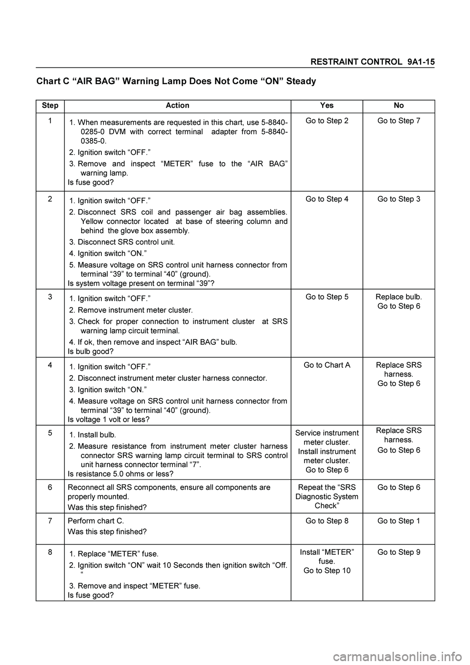
RESTRAINT CONTROL 9A1-15
Chart C “AIR BAG” Warning Lamp Does Not Come “ON” Steady
Step Action Yes No
1
1. When measurements are requested in this chart, use 5-8840-
0285-0 DVM with correct terminal adapter from 5-8840-
0385-0.
2. Ignition switch “OFF.”
3. Remove and inspect “METER” fuse to the “AIR BAG”
warning lamp.
Is fuse good? Go to Step 2 Go to Step 7
2
1. Ignition switch “OFF.”
2. Disconnect SRS coil and passenger air bag assemblies.
Yellow connector located at base of steering column and
behind the glove box assembly.
3. Disconnect SRS control unit.
4. Ignition switch “ON.”
5. Measure voltage on SRS control unit harness connector from
terminal “39” to terminal “40” (ground).
Is system voltage present on terminal “39”? Go to Step 4 Go to Step 3
3
1. Ignition switch “OFF.”
2. Remove instrument meter cluster.
3. Check for proper connection to instrument cluster at SRS
warning lamp circuit terminal.
4. If ok, then remove and inspect “AIR BAG” bulb.
Is bulb good? Go to Step 5 Replace bulb.
Go to Step 6
4
1. Ignition switch “OFF.”
2. Disconnect instrument meter cluster harness connector.
3. Ignition switch “ON.”
4. Measure voltage on SRS control unit harness connector from
terminal “39” to terminal “40” (ground).
Is voltage 1 volt or less? Go to Chart A Replace SRS
harness.
Go to Step 6
5
1. Install bulb.
2. Measure resistance from instrument meter cluster harness
connector SRS warning lamp circuit terminal to SRS control
unit harness connector terminal “7”.
Is resistance 5.0 ohms or less? Service instrument
meter cluster.
Install instrument
meter cluster.
Go to Step 6 Replace SRS
harness.
Go to Step 6
6 Reconnect all SRS components, ensure all components are
properly mounted.
Was this step finished? Repeat the “SRS
Diagnostic System
Check” Go to Step 6
7 Perform chart C.
Was this step finished? Go to Step 8 Go to Step 1
8
1. Replace “METER” fuse.
2. Ignition switch “ON” wait 10 Seconds then ignition switch “Off.
“
3. Remove and inspect “METER” fuse.
Is fuse good? Install “METER”
fuse.
Go to Step 10 Go to Step 9
Page 86 of 4264
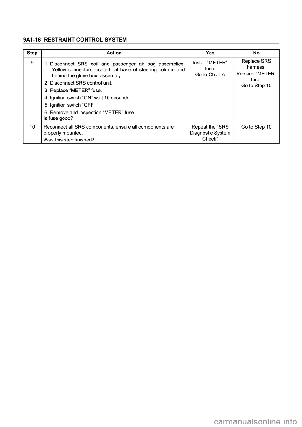
9A1-16 RESTRAINT CONTROL SYSTEM
Step Action Yes No
9
1. Disconnect SRS coil and passenger air bag assemblies.
Yellow connectors located at base of steering column and
behind the glove box assembly.
2. Disconnect SRS control unit.
3. Replace “METER” fuse.
4. Ignition switch “ON” wait 10 seconds.
5. Ignition switch “OFF”.
6. Remove and inspection “METER” fuse.
Is fuse good? Install “METER”
fuse.
Go to Chart A Replace SRS
harness.
Replace “METER”
fuse.
Go to Step 10
10 Reconnect all SRS components, ensure all components are
properly mounted.
Was this step finished? Repeat the “SRS
Diagnostic System
Check” Go to Step 10
Page 88 of 4264
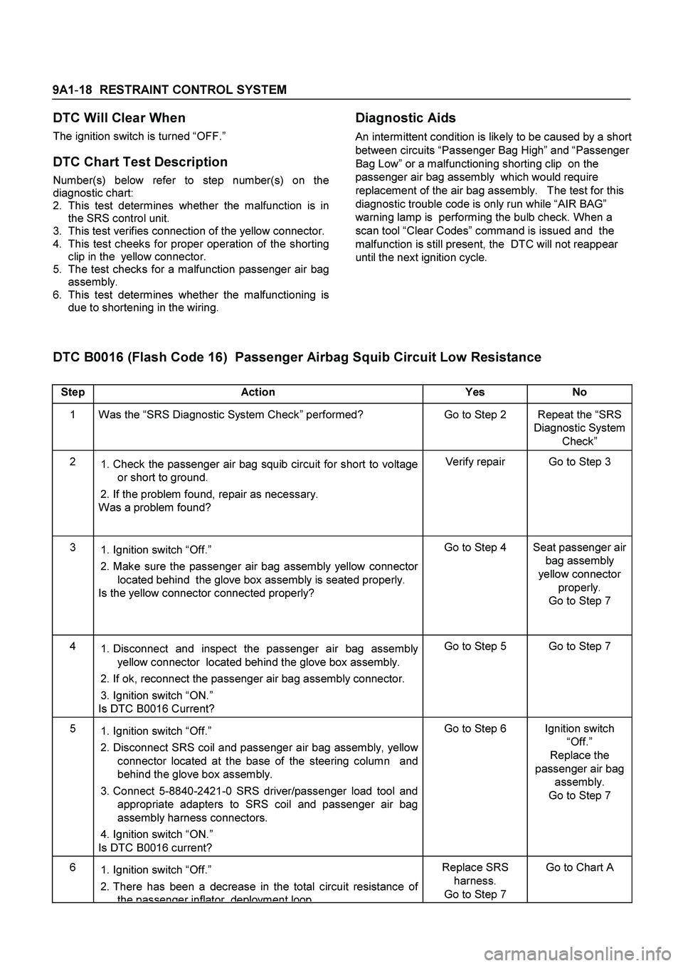
9A1-18 RESTRAINT CONTROL SYSTEM
DTC Will Clear When
The ignition switch is turned “OFF.”
DTC Chart Test Description
Number(s) below refer to step number(s) on the
diagnostic chart:
2.
This test determines whether the malfunction is in
the SRS control unit.
3.
This test verifies connection of the yellow connector.
4.
This test cheeks for proper operation of the shorting
clip in the yellow connector.
5.
The test checks for a malfunction passenger air bag
assembly.
6.
This test determines whether the malfunctioning is
due to shortening in the wiring.
Diagnostic Aids
An intermittent condition is likely to be caused by a short
between circuits “Passenger Bag High” and “Passenger
Bag Low” or a malfunctioning shorting clip on the
passenger air bag assembly which would require
replacement of the air bag assembly. The test for this
diagnostic trouble code is only run while “AIR BAG”
warning lamp is performing the bulb check. When a
scan tool “Clear Codes” command is issued and the
malfunction is still present, the DTC will not reappear
until the next ignition cycle.
DTC B0016 (Flash Code 16) Passenger Airbag Squib Circuit Low Resistance
Step Action Yes No
1 Was the “SRS Diagnostic System Check” performed? Go to Step 2 Repeat the “SRS
Diagnostic System
Check”
2
1. Check the passenger air bag squib circuit for short to voltage
or short to ground.
2. If the problem found, repair as necessary.
Was a problem found? Verify repair Go to Step 3
3
1. Ignition switch “Off.”
2. Make sure the passenger air bag assembly yellow connector
located behind the glove box assembly is seated properly.
Is the yellow connector connected properly? Go to Step 4 Seat passenger air
bag assembly
yellow connector
properly.
Go to Step 7
4
1. Disconnect and inspect the passenger air bag assembly
yellow connector located behind the glove box assembly.
2. If ok, reconnect the passenger air bag assembly connector.
3. Ignition switch “ON.”
Is DTC B0016 Current? Go to Step 5 Go to Step 7
5
1. Ignition switch “Off.”
2. Disconnect SRS coil and passenger air bag assembly, yellow
connector located at the base of the steering column and
behind the glove box assembly.
3. Connect 5-8840-2421-0 SRS driver/passenger load tool and
appropriate adapters to SRS coil and passenger air bag
assembly harness connectors.
4. Ignition switch “ON.”
Is DTC B0016 current? Go to Step 6 Ignition switch
“Off.”
Replace the
passenger air bag
assembly.
Go to Step 7
6
1. Ignition switch “Off.”
2. There has been a decrease in the total circuit resistance of
the passenger inflator deployment loop
Replace SRS
harness.
Go to Step 7 Go to Chart A
Page 91 of 4264
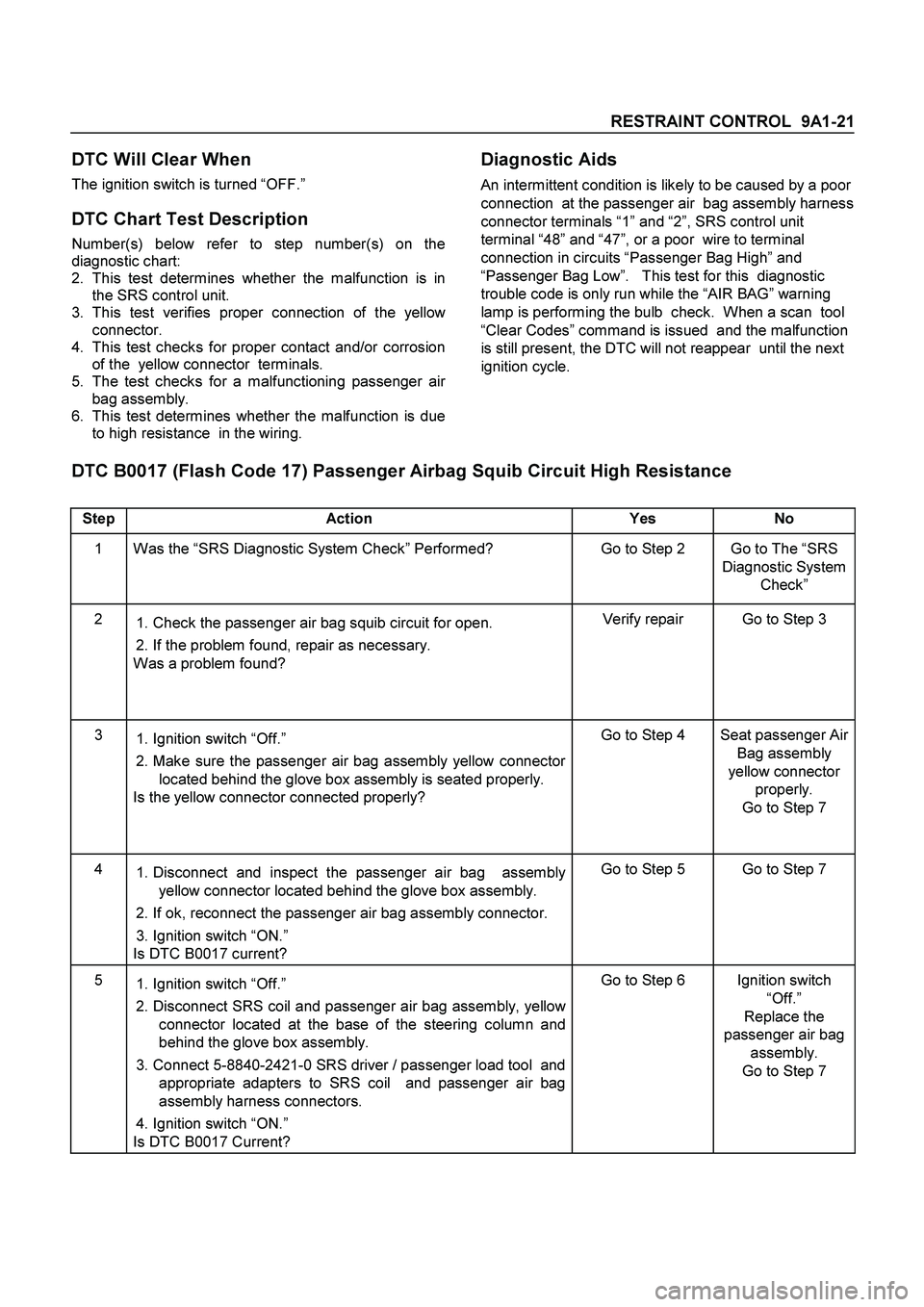
RESTRAINT CONTROL 9A1-21
DTC Will Clear When
The ignition switch is turned “OFF.”
DTC Chart Test Description
Number(s) below refer to step number(s) on the
diagnostic chart:
2.
This test determines whether the malfunction is in
the SRS control unit.
3.
This test verifies proper connection of the yellow
connector.
4.
This test checks for proper contact and/or corrosion
of the yellow connector terminals.
5.
The test checks for a malfunctioning passenger ai
r
bag assembly.
6.
This test determines whether the malfunction is due
to high resistance in the wiring.
Diagnostic Aids
An intermittent condition is likely to be caused by a poor
connection at the passenger air bag assembly harness
connector terminals “1” and “2”, SRS control unit
terminal “48” and “47”, or a poor wire to terminal
connection in circuits “Passenger Bag High” and
“Passenger Bag Low”. This test for this diagnostic
trouble code is only run while the “AIR BAG” warning
lamp is performing the bulb check. When a scan tool
“Clear Codes” command is issued and the malfunction
is still present, the DTC will not reappear until the next
ignition cycle.
DTC B0017 (Flash Code 17) Passenger Airbag Squib Circuit High Resistance
Step Action Yes No
1 Was the “SRS Diagnostic System Check” Performed? Go to Step 2 Go to The “SRS
Diagnostic System
Check”
2
1. Check the passenger air bag squib circuit for open.
2. If the problem found, repair as necessary.
Was a problem found? Verify repair Go to Step 3
3
1. Ignition switch “Off.”
2. Make sure the passenger air bag assembly yellow connector
located behind the glove box assembly is seated properly.
Is the yellow connector connected properly? Go to Step 4 Seat passenger Air
Bag assembly
yellow connector
properly.
Go to Step 7
4
1. Disconnect and inspect the passenger air bag assembly
yellow connector located behind the glove box assembly.
2. If ok, reconnect the passenger air bag assembly connector.
3. Ignition switch “ON.”
Is DTC B0017 current? Go to Step 5 Go to Step 7
5
1. Ignition switch “Off.”
2. Disconnect SRS coil and passenger air bag assembly, yellow
connector located at the base of the steering column and
behind the glove box assembly.
3. Connect 5-8840-2421-0 SRS driver / passenger load tool and
appropriate adapters to SRS coil and passenger air bag
assembly harness connectors.
4. Ignition switch “ON.”
Is DTC B0017 Current? Go to Step 6 Ignition switch
“Off.”
Replace the
passenger air bag
assembly.
Go to Step 7
Page 97 of 4264

RESTRAINT CONTROL 9A1-27
DTC Will Set When
The combined resistance of the driver air bag
assembly, SRS Coil assembly, harness wiring circuits
“Driver Bag High” and “Driver Bag Low”, and connector
terminal contact is above a specified value. This test is
run once each ignition cycle during the “Resistance
Measurement Test” when:
1.
No “higher priority faults” are detected during “Turn–
ON”
2.
“Ignition 1” voltage is in the specified value.
Action Taken
SRS control unit turns “ON” the “AIR BAG” warning
lamp and sets DTC B0022.
DTC Will Clear When
The ignition switch is turned “OFF.”
DTC Chart Test Description
Number(s) below refer to circled number(s) on the
diagnostic chart:
2.
This test determines whether the malfunction is in
the SRS control unit.
3.
This test verifies proper connection of the yellow
connector at the base of the steering column.
4.
This test checks for proper operation of the shorting
clip in the yellow connector.
5.
This test isolate the malfunction to one side of the
SRS coil assembly yellow connector located at the
base of steering column.
6.
This test determines whether the malfunction is due
to shortening in the wiring.
7.
This test determines whether the malfunction is in
the SRS coil assembly or the driver air bag
assembly.
Diagnostic Aids
An intermittent condition is likely to be caused by a short
between circuit “Driver Bag High” or “Driver Bag Low”
or a malfunctioning shorting clip on the driver air bag
assembly or SRS coil assembly which would require
replacement of the component. The test for this
diagnostic trouble code is only run while the “AIR BAG”
warning lamp is performing the bulb check. When a
scan tool “Clear Codes” command is issued and the
malfunction is still present, the DTC will not reappear
until the next ignition cycle.
DTC B0022 (Flash Code 22) Driver Airbag Squib Circuit Low Resistance
Step Action Yes No
1 Perform the “SRS Diagnostic System Check.”
Was the “SRS Diagnostic System Check” performed? Go to Step 2 Go to the “SRS
Diagnostic System
Check”
2
1. Check the driver air bag squib circuit for short to voltage or
short to ground.
2. If the problem found, repair as necessary.
Was a problem found? Verify repair Go to Step 3
3
1. Ignition switch “OFF.”
2. Make sure the SRS coil assembly yellow connector located
at the base of steering column is seated properly.
Is the connector connected properly? Go to Step 4 Seat driver air bag
assembly
connector
properly.
Go to Step 8
4
1. Disconnect and inspect the SRS coil assembly yellow
connector located base of steering column.
2. If ok, reconnect the SRS coil assembly yellow connector.
3. Ignition switch “ON.”
Is DTC B0022 current? Go to Step 5 Go to Step 8
Page 98 of 4264
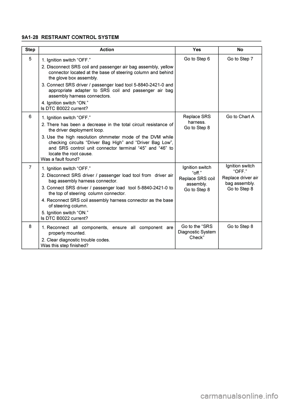
9A1-28 RESTRAINT CONTROL SYSTEM
Step Action Yes No
5
1. Ignition switch “OFF.”
2. Disconnect SRS coil and passenger air bag assembly, yellow
connector located at the base of steering column and behind
the glove box assembly.
3. Connect SRS driver / passenger load tool 5-8840-2421-0 and
appropriate adapter to SRS coil and passenger air bag
assembly harness connectors.
4. Ignition switch “ON.”
Is DTC B0022 current? Go to Step 6 Go to Step 7
6
1. Ignition switch “OFF.”
2. There has been a decrease in the total circuit resistance of
the driver deployment loop.
3. Use the high resolution ohmmeter mode of the DVM while
checking circuits “Driver Bag High” and “Driver Bag Low”,
and SRS control unit connector terminal “45” and “46” to
locate the root cause.
Was a fault found? Replace SRS
harness.
Go to Step 8 Go to Chart A
7
1. Ignition switch “OFF.”
2. Disconnect SRS driver / passenger load tool from driver air
bag assembly harness connector.
3. Connect SRS driver / passenger load tool 5-8840-2421-0 to
the top of steering column connector.
4. Reconnect SRS coil assembly harness connector as the base
of steering column.
5. Ignition switch “ON.”
Is DTC B0022 current? Ignition switch
“off.”
Replace SRS coil
assembly.
Go to Step 8 Ignition switch
“OFF.”
Replace driver air
bag assembly.
Go to Step 8
8
1. Reconnect all components, ensure all component are
properly mounted.
2. Clear diagnostic trouble codes.
Was this step finished? Go to the “SRS
Diagnostic System
Check” Go to Step 8