ISUZU TFS SERIES 1997 Workshop Manual
TFS SERIES 1997
ISUZU
ISUZU
https://www.carmanualsonline.info/img/61/57182/w960_57182-0.png
ISUZU TFS SERIES 1997 Workshop Manual
Page 2 of 1600
4B-6 REAR AXLE
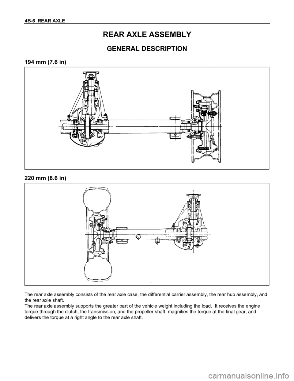
REAR AXLE ASSEMBLY
GENERAL DESCRIPTION
194 mm (7.6 in)
220 mm (8.6 in)
The rear axle assembly consists of the rear axle case, the differential carrier assembly, the rear hub assembly, and
the rear axle shaft.
The rear axle assembly supports the greater part of the vehicle weight including the load. It receives the engine
torque through the clutch, the transmission, and the propeller shaft, magnifies the torque at the final gear, and
delivers the torque at a right angle to the rear axle shaft.
Page 113 of 1600
4C1-50 FRONT WHEEL DRIVE
INSPECTION AND REPAIR
Make necessary correction or parts replacement if wear, damage or any other abnormal conditions are found
through inspection.
For inspection and servicing of disc caliper, and relative parts, refer to Section 5 “Service Brakes”.
Hub
Hub bearing, oil seal
Knuckle spindle
Disc
Caliper
Free wheeling hub parts
(Option)
Clutch, knob, follower, inner, ring and
spring
Visual Check
Check the following parts for wear, damage or other abnormal
conditions.
Page 117 of 1600
4C1-54 FRONT WHEEL DRIVE
FRONT HUB AND DISC (Automatic Locking Hub)
DISASSEMBLY
Disassembly Steps
1. Bolt
2. Hub cap
3. Housing assembly
4. Snap ring and shim
5. Drive clutch assembly
6. Inner cam
7. Lock washer8. Hub nut
9. Hub and disc assembly
10. Outer bearing and outer race
11. Oil seal
12. Inner bearing and outer race
13. Bolt
14. Wheel pin
Page 120 of 1600
FRONT WHEEL DRIVE 4C1-57
INSPECTION AND REPAIR
Make necessary correction or parts replacement if wear, damage or any other abnormal conditions are found
through inspection.
For inspection and servicing of disc caliper, and relative parts, refer to Section 5 “Service Brakes”.
Hub
Hub bearing, oil seal
Knuckle spindle
Disc
Caliper
Automatic locking hubs
Visual Check
Check the following parts for wear, damage or other abnormal
conditions.
Inside Diameter of Housing
mm(in)
Standard Limit
65.04 (2.61) 65.24 (2.568)
Inspect flange surface A and B for excessive wear.
Drive Clutch Section Dimensions “L”
mm(in)
Standard Limit
8.2 (0.323) 7.8 (0.37)
Holdout Ring Axial Play of the Drive
Clutch Assembly
mm(in)
Standard Limit
0.3 (0.012) or less 0.4 (0.016)
Page 121 of 1600
4C1-58 FRONT WHEEL DRIVE
Outside Diameter of the Drive Clutch
Assembly
mm(in)
Standard Limit
64.75 (2.55) 64.55 (2.54)
Page 122 of 1600
FRONT WHEEL DRIVE 4C1-59
REASSEMBLY
Reassembly Steps
1. Wheel pin
2. Bolt
3. Inner bearing and outer race
4. Outer bearing and outer race
5. Oil seal
6. Hub and disc assembly
7. Hub nut
8. Lock washer
9. Inner cam
10. Drive clutch assembly
11. Snap ring and shim
12. Housing assembly
13. Hub cap
14. Washer and bolt
Page 126 of 1600
FRONT WHEEL DRIVE 4C1-63
(3) Install special tool 5-8840-2126-0 to axle shaft by 5-8840-
2125-0 until it comes into contact with the lock washer.
(4) Using feeler gauge, measure clearance “t” between the
special tool and the snap ring groove of the axle shaft.
(5) If clearance “t” is larger than snap ring groove, shims must
be installed select shims so that clearance “t” is 0 to 0.1 mm
(0 to 0.0039 in).
Thickness shims; 0.2, 0.3, 0.5, 1.0 mm
(6) Remove special tool 5-8840-2126-0, leaving the inner cam
in position.
10.Drive Clutch Assembly
Apply multipurpose grease or hub bearing grease to the
following portions.
(1) Axle shaft splines
Page 127 of 1600
4C1-64 FRONT WHEEL DRIVE
“A” groove and “B” portion
g(oz)
“A” Groove 7 (0.25)
“B” portion 3 (0.11)
“C” circumference and “D” portion
g(oz)
“C” circumference 8 (0.29)
“D” portion 4 (0.15)
(2) Align the cut part of the drive clutch assembly with the
protudent part of inner cam.
(3) Engage the cam teeth of the drive clutch assembly to that of
the inner cam by turning the axle shaft.
11.Snap Ring and Shims
(1) Install shims (selected above) to axle by hand.
Note :
Always use a new snap ring.
(2) Install special tool 5-8840-2125-0 (B) to axle.
(3) Install snap ring to tool.
(4) Install tool driver 5-8840-2125-0 (A).
(5) Pull out the axle shaft fully by pulling the tool 5-8840-2125-0
(B) and install snap ring to axle by pushing on tool driver 5-
8840-2125-0 (A).
(6) Remove tool from axle.
Snap ring installer : 5-8840-2125-0
(J-36835)
Page 129 of 1600
4C1-66 FRONT WHEEL DRIVE
FRONT HUB AND DISC (Manual Locking Hub)
DISASSEMBLY
Disassembly Steps
1. Bolt
2. Housing assembly
3. Snap ring and shim
4. Body assembly
5. Lock washer
6. Hub nut
7. Hub and disc assembly
8. Outer bearing
9. Oil seal
10. Inner bearing
11. Clutch assembly12. Snap ring
13. Knob
14. Compression spring
15. Follower
16. Retaining spring
17. Detent ball and spring
18. X-ring
19. Snap ring
20. Inner assembly
21. Snap ring
22. Ring
23. Spacer
Page 130 of 1600
FRONT WHEEL DRIVE 4C1-67
Important Operations
1. Bolt
Before removal, shift transfer lever into “2H” position and set
free wheeling hub knob into “FREE” position.
6. Hub Nut
Wrench : 5-8840-2117-0
(J-36827)
Refer to Section 5 “Brake” for disc brake
caliper removal procedure.7. Hub and Disc Assembly
Before disassembly, remove the disc brake caliper assembly
and hang it on the frame with wires.
11.Clutch Assembly
While pushing follower knob, turn clutch assembly clockwise
and then remove clutch assembly from knob.
16.Retaining Spring
Remove retaining spring from clutch assembly by turning it
counterclockwise.


